单馈点圆极化微带天线
宽带圆极化微带天线分析与设计

宽带圆极化微带天线分析与设计一、本文概述本文旨在深入探讨宽带圆极化微带天线的分析与设计。
随着无线通信技术的飞速发展,天线作为无线通信系统的关键组成部分,其性能直接影响到整个系统的传输质量和效率。
宽带圆极化微带天线作为一种重要的天线类型,具有宽频带、圆极化、低剖面、易集成等优点,因此在卫星通信、移动通信、雷达系统等领域具有广泛的应用前景。
本文将首先介绍宽带圆极化微带天线的基本原理和特性,包括其辐射机制、极化特性、带宽特性等。
随后,将详细分析宽带圆极化微带天线的设计方法,包括天线尺寸的选择、馈电方式的设计、介质基板的选取等。
在此基础上,将探讨影响天线性能的关键因素,如阻抗匹配、交叉极化、增益等,并提出相应的优化策略。
本文还将通过具体的案例分析,展示宽带圆极化微带天线在实际应用中的性能表现。
通过对比分析不同设计方案下的天线性能,为工程师和研究者在实际应用中提供有益的参考。
本文将总结宽带圆极化微带天线的设计与优化策略,并展望其未来的发展趋势和应用前景。
通过本文的研究,旨在为宽带圆极化微带天线的分析与设计提供理论支持和实践指导。
二、圆极化微带天线的基本原理圆极化微带天线是一种能够在空间中产生圆形极化波的天线,它具有独特的电磁辐射特性,广泛应用于无线通信、雷达探测和卫星通信等领域。
了解圆极化微带天线的基本原理对于其分析与设计至关重要。
圆极化波是一种电磁波,其电场矢量在空间中随时间旋转,形成一个圆形的轨迹。
圆极化微带天线通过特定的设计和构造,能够在其辐射区域内产生这样的圆形极化波。
这种波形的特性在于,无论接收天线的极化方式如何,圆极化波都能在一定程度上被接收,因此具有更好的抗干扰能力和更广泛的适用性。
圆极化微带天线的基本原理主要基于电磁场理论和天线辐射原理。
它通过在微带天线的辐射贴片上引入特定的相位差,使得天线的两个正交分量产生90度的相位差,从而形成圆极化波。
这种相位差可以通过在辐射贴片上刻蚀特定的槽口或引入附加的相位延迟线来实现。
右旋圆极化矩形微带天线设计

右旋圆极化矩形微带天线设计一、引言大多数情况下,矩形微带天线工作于线极化模式,但是通过采用特殊的馈电机制及对微带贴片的处理,它也可以工作于圆极化和椭圆极化模式。
圆极化的关键是激励起两个极化方式相互正交的线极化波,当这两个模式的线极化波幅度相等,且相位相差90度时,就能得到圆极化的辐射。
矩形微带天线获得圆极化特性的馈电方式有两种:一种是单点馈电,另一种是正交馈电。
本文采用单点馈电。
我们知道,当同轴线的馈电点位于辐射贴片的对角线位置时,可以激发TM10和TM01两个模式,这两个模式的电场方向相互垂直。
在设计中,我们让辐射贴片的长度L和宽度W相等,这样激发的TM10和TM01两个模式的频率相同,强度相等,而且两个模式的电场相位差为零。
若辐射贴片的谐振长度为Lc,我们微调谐振长度略偏离谐振,即一边的长度为L1,另一边的长度为W1,且L1>W1,这样前者对应一个容抗Y1=G-jB,后者对应一个感抗Y2=G+jB,只要调整L1和W1的值,使得每一组的电抗分量等于阻抗的实数部分,及B=G,则两阻抗大小相等,相位分别为-45度和+45度,这样就满足了圆极化的条件,从而构成了圆极化的微带天线。
其极化旋向取决于馈电点接入位置,当馈电点在如图1-1的A点时,产生右旋圆极化;当馈电点在图1-1的B 点时,产生左旋圆极化波。
图1-1 单馈点圆极化矩形微带天线结构二、结构设计设计微带天线的第一步是选择合适的介质基片,假设介质的介电常数为εr,对于工作频率为f的矩形微带天线,可以用如下的公式估算辐射贴片的宽度:21212-+=)ε(fcW r(1)其中,c是光速。
辐射贴片的长度一把取为2cλ,其中cλ是介质内的导波波长,考虑到边缘缩短效应后,实际的辐射贴片长度为:LfcLe∆-=22ε(2)其中,eε是有效介电常数,L∆是等效辐射缝隙长度,它们可以分别用下式计算,即为:211212121-+-++=)(wh r r e εεε).)(.().)(.(.8025802640304120+-++=∆h w h w L e e εε对于同轴馈电的微带贴片天线,在确定了贴片长度L 和宽度W 之后,还需要确定同轴线馈点的位置,馈电的位置会影响输入阻抗,通常要求是50Ω阻抗匹配。
2014圆极化微带天线技术_赵云

圆极化微带天线技术赵云苏桦奚嘉舣崔博华(电子科技大学微固学院四川成都 610000)摘 要:圆极化微带天线由于良好的电磁性能,抑制雨雾干扰和抗多径反射的能力,被广泛应用在通信、雷达、电子对抗、电视广播等领域。
简要论述圆极化的基本概念与实现条件,并介绍几种实现圆极化的方法。
最后展望一下圆极化微带天线的发展趋势。
关键词:微带天线;圆极化中图分类号:TN8 文献标识码:A 文章编号:1671-7597(2011)0120010-010 引言来实现,比如在贴片表面切角,在圆形表面开槽等等;在单馈法设计中的难点是几何微扰的确定,即如何确定简并模分离元的大小、位置及恰当的微带天线由于具有剖面低、重量轻、体积小、易于共形和批量生产等馈点,以激发两正交相位差90°的简并模。
使用单馈法实现圆极化天线的优点,广泛应用于测量和通讯各个领域,而圆极化微带天线在当前的应用优点是无需外加的相移网络和功率分配器,结构简单,成本低,易于小型更加广泛。
圆极化微带天线在实际应用方面的主要优势有[1]:1)任意的化,但是它的缺点是带宽窄,这是由其高Q值的谐振本性决定的。
因此,极化电磁波均可分解为两个旋向相反的圆极化波,如对于线极化波来说,扩展这种天线的圆极化带宽的关键在于减小品质因数Q值。
可以分解为两个反向等幅的圆极化波。
因此,任意极化的电磁波均可被圆2.2 多馈法实现圆极化。
多馈法是由多个馈电点给微带天线馈电,由极化天线接收,而圆极化天线发射的电磁波则可被任意极化的天线接收馈电网络保证实现圆极化工作条件,这种结构通常可以得到与阻抗带宽相到,故电子侦察和干扰中普遍采用圆极化天线;2)在通信、雷达的极化当的圆极化带宽。
多馈法一般分为双馈点和四馈点两种方式,其中双馈点分集工作和电子对抗等应用中广泛利用圆极化天线的旋向正交性;3)圆方式利用功分器或电桥输出的两个幅度相等,相位相差90°的两支路对贴极化波入射到对称目标(如平面、球面等)时旋向逆转,所以圆极化天线片馈电,激发两个正交工作模式,达到圆极化工作条件。
圆极化微带天线发展现状研究
• 62•圆极化微带天线发展现状研究武警工程大学研究生大队 孟志豪 张怿成本文综述了圆极化微带天线的发展现状,对圆极化微带天线的原理、实现方法、改进方法进行了归纳,并分别举了具有一定代表性的例子,最后对圆极化微带天线的发展趋势进行了总结。
引言:天线是发射和接收电磁波的部件,改善天线的综合性能,对于优化整个移动通信系统有着重要意义,圆极化微带天线由于其尺寸小、可抗多径干扰等优良特性而被人们青睐,特别是在无线通信系统中有着很高的应用价值。
因此,设计出外部尺寸小型化、辐射特性宽带化的新型圆极化微带天线一直是研究的热点,具有很高的研究价值。
1.圆极化微带天线原理圆极化微带天线是一种可以发射圆极化波的微带天线,由于圆极化波的特性,圆极化微带天线的相对位置可以自由变化,极化匹配的实现更加容易,还可以可以有效抑制多径干扰。
所以圆极化天线可以很好地保证通信的畅通,被广泛应用于移动通信系统当中。
其主要性能指标包括:(1)输入阻抗带宽,一般用驻波比(回波损耗)来定义,反映天线与馈线的匹配效果,一般将满足驻波比小于1.5的频率范围定义为阻抗带宽。
(2)轴比带宽,是椭圆极化波长轴与短轴之间的比值,一般将满足轴比低于3db 的频率范围定义为轴比带宽。
(3)增益带宽,增益是天线在某一点场强平方的归一化值,轴比带宽是将满足增益高于某一特定值的频率范围定义为增益带宽。
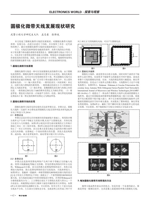
2.圆极化微带天线的实现圆极化微带天线常见的实现形式包括单馈点法、多馈点法、圆极化天线阵(吴建军.M合馈电宽带圆极化天线及其阵列技术研究[D].西安电子科技大学,2016)2.1 单馈点法单馈点法是在原先具有规则形状的辐射贴片基础上,利用简并模分离单元产生两个等幅正交的简并模,从而产生圆极化波。
具体实现方法是引入几何微扰,如图1所示就是在原先相对规则的正方形贴片基础上切去一对三角形切角,图2所示就是在原先圆形贴片的基础上切去了一对正方形切角,该方法难点是要先确定合适的简并模分离单元的几何参数,还要确定一个很好的馈点的位置。
圆极化微带天线的设计及研究

摘要微带天线具有体积小,重量轻,低剖面,制造成本低,易于批量生产,易于和微带线路集成等特点,能得到单方向的宽瓣方向图,易于实现双频段、双极化等多功能工作。
这些优点使得微带天线在大约100MHz~100GHz宽广频域上,广泛应用于包括卫星通信、雷达、遥感、制导武器以及便携式无线电设备。
论文首先回顾了微带天线的发展史,介绍了它的结构、优缺点及应用,然后给出了微带天线的几种分析方法,包括传输线法,空腔模型法,积分方程法等,并介绍了微带天线圆极化的原理和实现方法以及微带天线的馈电方式。
然后在Ansoft HFSS中创建了一个单馈圆极化微带天线和双馈圆极化微带天线,分析了S11和VSWR参数,画出了方向图。
为了实现圆极化,进行了轴比的优化仿真,达到了较为理想的结果。
关键词:微带天线、圆极化、轴比AbstractThe microstrip antennas has the volume to be small, the weight is light, the low section plane, the production cost is low, easy volume production, easy and characteristics and so on microstrip line integration, can obtain the single direction wide petal directional diagram, easy to realize, the double polarization dual range and so on multi-purpose work. These merits cause the microstrip antennas in approximately the 100MHz-100GHz broad frequency range, widely applies in includes the satellite communication, the radar, the remote sensing, the guided weapon as well as the portable wireless apparatus.The paper first reviewed microstrip antennas's history, introduced its structure, the good and bad points and the application, then have given microstrip antennas's several analysis method, including the transmission long-base method, the cavity modeling, the integral equation law and so on, and introduced the microstrip antennas circular polarization's principle and realizes the method as well as microstrip antennas's feed method. Then AnSoft Hfss in the creation of a single-fed circular polarization microstrip antenna and double-fed circular polarization microstrip antenna and double-fed circular polarization microstrip antenna, the analysis of the S11 and VSWR parameters, to draw a pattern. In order to achieve circular polarization, the axis carried on the optimization simulation, to a more satisfactory results.Key words:microstrip antenna;circular polarization; axial ratio目录摘要 (I)ABSTRACT (II)目录 (III)第一章绪论 (1)§1.1微带天线的发展 (1)§1.2微带天线的定义和结构 (1)§1.3微带天线的优缺点 (2)§1.4微带天线的应用 (3)第二章微带天线的原理技术 (4)§2.1微带天线的辐射机理 (4)§2.2微带天线的分析方法 (5)§2.2.1传输线模型法 (5)§2.2.2空腔模型法 (8)§2.2.3积分方程法 (8)§2.3微带天线的馈电方法 (9)§2.4微带天线圆极化技术 (10)§2.4.1圆极化天线的原理 (10)§2.4.2圆极化实现技术 (11)§2.5其他形式的微带天线 (15)第三章圆极化微带天线的仿真与优化 (19)§3.1A NSOFT HFSS高频仿真软件的介绍 (19)§3.2圆极化微带天线的仿真优化 (19)§3.2.1圆极化微带天线的仿真设计 (19)§3.2.2天线轴比的优化 (22)第四章双馈圆极化微带天线的设计 (25)§4.1两路微带等功率分配器的设计与仿真 (25)§4.2双馈圆极化微带天线的仿真分析 (29)§4.2.1创建天线模型 (29)§4.2.2 优化天线模型 (33)致谢 (37)参考文献 (37)第一章绪论§1.1微带天线的发展微带天线的概念早在1953年就已经提出了,但并未引起工程界的重视。
一种单馈小型化宽波束双层圆极化微带天线

一种单馈小型化宽波束双层圆极化微带天线禹化龙;杨志刚;陈光【摘要】A compact single feed double layer circularly polarised microstrip antenna with low permittivity substrate is designed,centre cross-slot and peripheral cuts on each patch is proposed.The size of the antenna is reduced by four cutting slots.Centre cross-slot can improve the bandwidth,while peripheral cuts and proper feed location can realise circularly polarise of the antenna.As contrast to conventional microstrip antenna,the area of which is decreased approximately 37%.The antenna has a 800 beam width and a good gain performance,which is higher than 5.3 dB.%设计出一种单馈小型化宽波束双层圆极化微带天线,通过选取低介电常数的介质基片,在双层圆形贴片上分别刻四个槽减小天线的尺寸,中心开十字缝增加天线的阻抗带宽,在贴片边切角和贴片的对角线上选择合适的馈电位置实现圆极化,天线尺寸减少37%,天线方向图对称性好,波束宽度大于80°,增益大于5.3 dB。
【期刊名称】《中国电子科学研究院学报》【年(卷),期】2011(006)005【总页数】3页(P541-543)【关键词】小型化;宽波束;缝隙;圆极化天线【作者】禹化龙;杨志刚;陈光【作者单位】中国电子科技集团公司第27研究所,郑州450047;中国电子科技集团公司第27研究所,郑州450047;中国电子科技集团公司第27研究所,郑州450047【正文语种】中文【中图分类】TN820 引言微带天线以其低轮廓、可共形、易集成、造价低等优点近年来得到广泛应用。
低剖面宽带圆极化微带天线详细教程

低剖面宽带圆极化微带天线详细教程
微带天线由于其低成本、低轮廓、小体积、易于集成和共形,以及能方便地实现线极化和圆极化等优点在各种通信系统中得到了广泛的应用。
单馈点圆极化微带天线由于其简洁、紧凑的结构,得到了研究人员的广泛关注,但其设计难度远远超过线极化微带天线和多馈点圆极化微带天线。
常见的单馈点圆极化微带天线形式主要有开槽贴片、方形切角贴片、准方形贴片和圆形贴片。
由于它们的轴比带宽较窄,一般不足3%,严重制约了单馈点圆极化微带天线的应用。
为了展宽微带天线的带宽,人们常采用层叠型微带结构。
该结构上下两层辐射单元分别对应两个谐振频率,通过调节辐射贴片的尺寸和上下间距使两个谐振带宽紧贴,从而形成双峰谐振,很好的拓展了微带天线的带宽。
采用准方形的层叠结构,均获得了13%以上的轴比带宽;Kwok Lun Chung等人采用微带线边馈的层叠方形切角贴片结构,获得了8%的3dB轴
比带宽;采用探针底馈式馈电的层叠方形切角贴片天线获得了12.7%的3dB 轴比带宽。
本文在方形切角贴片可实现不同旋向圆极化的两个馈点位置都加上端口,一个端口馈电,另一端口附加匹配阻抗。
通过馈电端口实现相应圆极化的工作方式,另一端口的阻抗匹配则起到了降低剖面高度的作用。
另外,本文天线采用由两层方形切角微带贴片层叠放置的结构,形成双峰谐振回路得到了较宽的轴比带宽。
圆极化微带天线的设计与应用毕业设计[管理资料]
![圆极化微带天线的设计与应用毕业设计[管理资料]](https://img.taocdn.com/s3/m/cf8286930b1c59eef9c7b4a5.png)
太原理工大学毕业设计(论文)任务书圆极化微带天线的研究与设计摘要微带天线是近30年来逐渐发展起来的一类新型天线。
早在1953年就提出了微带天线的概念,但并未引起工程界的重视,自从20世纪70年代中期微带天线理论得到很大发展。
由于微带天线体积小、重量轻、馈电方式灵活、成本低、易于与目标共形等优点而深受人们亲睐,在雷达、移动通信、卫星通信、全球卫星定位系统等领域得到广泛的应用。
圆极化作为微带天线理论和技术应用的一个重要分支,被广泛的运用于雷达、导航、卫星等电子系统中。
由于其特性,使得收发天线间有很强的角度位置定位灵活性,并且能减小信号的多路径干扰和其他的一些影响。
本文对圆极化微带天线进行了深入研究,具体工作如下:1、文中首先阐述了微带天线的基本理论和主要设计方法,分析了微带天线圆极化有几种方法。
并对比分析方法的优劣,哪种方法更适合什么样的研究方向,为微带天线双馈圆极化的设计提供了依据。
2、微带天线的圆极化技术,重点研究了矩形贴片天线通过切角和双馈电的方式实现圆极化。
采用仿真软件Ansoft HFSS对其进行仿真设计,并对结果进行对比,找到合适的馈电点和馈电网络。
本文所设计的圆极化微带天线具有普遍适用性,能满足不同形状的要求,可提高驻波比带宽,抑制交叉极化,提高轴比,但是馈电网络复杂,成本比较高,尺寸也比较大,有一定的局限性。
关键词:圆极化,微带天线,馈电网络,HFSSCircularly polarized microstrip antenna research and designABSTRACTThe microstrip antennas is a kind of new antenna which in the recent 30 years develop gradually. As early as put forward microstrip antennas's concept in 1953, but has not brought to the engineering attention, obtained more development since the mid-1970s microstrip antennas theory.It is small as a result of the microstrip antennas volume, the weight is light, the feed way is flexible, cost low, easy and merits and so on goal altogether shape, but the depth is loved by the people , in the radar, the mobile communication, the satellite communication, domains and so on whole world satellite positioning system obtains the widespread application.The circular polarization takes the microstrip antennas theory and a technical application important branch, by widespread utilization in electronic systems and so on radar, guidance, satellite. As a result of its characteristic, enables between the dual-mode antenna to have the very strong angle position localization flexibility, and can reduce the signal the multi-way disturbance and other influences.This article has conducted the deep research to the circular polarization microstrip antennas, the concrete work is as follows in1.the article first elaborated microstrip antennas's elementary theory and the main project analysis method, analyzed microstrip antennas's circular polarization to have several methods. And the contrastive analysis method's fit and unfit quality, which method suits what research direction, has provided the basis for the microstrip antennas double-fed circular polarization's design.2.microstrip antennas's circular polarization technology, studied the rectangle to paste the piece antenna with emphasis realizes the circular polarization through the tangential angle and the double feed way. Uses simulation software Ansoft HFSS to carry on the simulation design to it, and carries on the contrast to the result, found the appropriate feeding point and the feed network.This article designs the circular polarization microstrip antennas has the universalserviceability, can satisfy the different shape the request, may enhance the standing-wave ratio band width, suppresses the cross polarization, enhances the axial ratio, but the feed network is complex, the cost comparison is high, the size is also quite big, has certain limitation.key word: Circular polarization, microstrip antennas, feed network,HFSS目录摘要 (I)ABSTRACT (II)第一章绪论 (1) (1) (2)第二章微带天线基本理论 (3) (3) (3) (4) (4) (4) (5) (6) (6) (7) (7) (8) (8) (9) (10) (10) (10) (11) (11) (12) (12) (12) (13)第三章圆极化微带天线 (15) (15) (16) (17) (18) (19) (19) (19) (19) (19) (19) (21) (21) (21) (21) (22) (22)第四章仿真分析 (26) (26) (26) (26): (26) (26): (27)矩形贴片天线切角圆极化 (27) (27) (27) (28) (28) (30)矩形贴片天线外加馈电网络圆极化 (34) (34) (35)本章小结 (38)结束语 (40)参考文献 (41)致谢 (42)附录英文资料及译文 (43)第一章绪论课题背景随着科学技术的飞速发展,现代社会已经进入信息时代,信息的快速而广泛的传递形成了现代社会最重要的特征。
- 1、下载文档前请自行甄别文档内容的完整性,平台不提供额外的编辑、内容补充、找答案等附加服务。
- 2、"仅部分预览"的文档,不可在线预览部分如存在完整性等问题,可反馈申请退款(可完整预览的文档不适用该条件!)。
- 3、如文档侵犯您的权益,请联系客服反馈,我们会尽快为您处理(人工客服工作时间:9:00-18:30)。
A Single-Feeding Circularly Polarized Microstrip Antenna With the Effect of Hybrid FeedingHyungrak Kim,Byoung Moo Lee,and Young Joong Yoon ,Member,IEEEAbstract—In this paper,a single series feeding cross-aperture coupled microstrip antenna with the effect of hybrid feeding is pro-posed and demonstrated.To better understand this antenna,the characteristics according to the variation of parameters are shown.This proposed antenna has the following advantages of the effect of hybrid feeding,improved axial ratio bandwidth (4.6%),high gain (8dBi),and flat 3-dB gain bandwidth (above 16.7%).In measured radiation patterns,we have 3-dB beamwidthof 30and good F/B of 20dB.Index Terms—Effect of hybrid feeding,microstrip antenna.I.I NTRODUCTIONWITH rapid development of wireless communication system,many kinds of circularly polarized (CP)antennas have been studied since CP antennas are often preferred in satellite communication,Global Positioning System (GPS),and radar system.In general,feeding structure of CP antenna may be divided into single and hybrid feeding.A single-feeding CP antenna provides simple structure,easy manufacture,and advantage in array with small size.However,it has narrow axial ratio bandwidth.Hybrid feeding gives complex structure,difficult manufacture,and increased antenna size,but it provides wide axial ratio bandwidth.Thus,in the design of CP antenna,a tradeoff of characteristics between two feeding methods is required.In CP antenna,axial ratio bandwidth is the most important factor in design since it is the most limiting factor for oper-ating factor.Therefore,many kinds of CP antennas have been studied to obtain wide axial ratio bandwidth [1]–[4].Recently,CP antennas to obtain wide axial ratio bandwidth using single feeding have been studied to improve disadvantages of hybrid feeding,e.g.,large antenna size and complex structure.Cross-aperture coupled microstrip antennas [5],[6]were proposed and analyzed,but it still has narrow axial ratio bandwidth (2.5%),narrow gain bandwidth (3.27%for 3-dB),and low antenna gain (5dBi).Another improvement was suggested by Aloni et al.[7],where traveling wave type CP antenna was introduced.How-ever,it has very low gain and low radiation efficiency,and nar-rower gain bandwidth than reasonably wide axial ratio band-width and impedance bandwidth.Therefore,not only wide axial ratio and impedance bandwidth,but also other enhanced charac-teristics,e.g.,high gain,flat-gain bandwidth,and similar radia-tion patterns in operating frequencies are needed in CP antenna for practical wireless communication system.Manuscript received February 20,2003;revised April 9,2003.The authors are with the Department of Electrical and Electronic Engi-neering,Yonsei University,Seoul,Korea (e-mail:okebari@mwnat.yonsei.ac.kr;binny@mwnat.yonsei.ac.kr;yjyoon@mwnat.yonsei.ac.kr).Digital Object Identifier10.1109/LAWP.2003.813382(a)(b)Fig.1.(a)Side view and (b)bottom view of the proposed antenna.In this paper,we propose a resonant type single series feeding CP microstrip antenna.Series feeding is suggested to obtain wide axial ratio bandwidth and flat gain bandwidth.Also,cross-aperture with short length is used to provide high gain.II.A NTENNA D ESIGNThe configuration of the proposed antenna is shown in Fig.1.It is composed of the two layers and air-gap.The rectangular patch,whose physical dimensions are 45mm 45mm at center frequency of 2.4GHz,is on the upper layer,and series feeding line under the lower layer is positioned close behind cross-aper-ture.For the upper and lower layer,Duroid 5880substrate with 0.5-oz copper,62-mil substrate height,and dielectric constant of 2.2and FR-4substrate with 1-oz copper,0.8-mm substrate height,and dielectric constant of 4.6are used,respectively.As shown in Fig.1(b),series feeding line is placed behind cross-aperture,and a quarter-wavelength section of feeding line is positioned between each arm of aperture to create the 90phase difference for circular polarization.Series feeding brings into sequential rotation of current on the surface of radiating1536-1225/03$17.00©2003IEEEpatch.Therefore,the proposed feeding structure has the effect of hybrid feeding without external hybrid components.Also,we made efforts to achieve high gain.In this study,by shorter aperture length than that of reported researches [5],[6],front to back ratio (F/B)of the proposed antenna is enhanced.As a result,we achieve F/B over than about 20dB at center frequency.Basically,the reciprocity method,as developed by Pozar [8],has been used for analyzing a conventional rectangular aperture antenna,where the aperture loadimpedance ,as seen from the feeding line,was expressedas(1)where,,,,,and are the microstrip charac-teristic impedance,the normalized modal voltage discontinuity,the aperture admittances looking into the antenna,the aperture admittances looking into the feeding line,and self admittance of the patch,respectively.In this study,cross-aperture and series feeding line are used.To analyze this structure,mutual interactions between each dif-ferent coupling points of the cross-slot should be considered.Aperturevoltages,in each four arm of the cross-aper-ture are expressed as[7](2)(3)(4)(5)whereisthenormalizedelectricfieldamplitudeintheaper-ture with respect to the feeding line current amplitude.Therefore,reflectioncoefficientsand slotimpedances for nth arm of cross-aperture are evaluated,respectively,by(6)(7)To optimize performance of the proposed antenna,the simu-lation software Ensemble is used in this study.We present simu-lated axial ratios and return losses as the variation of the length of cross-aperture,width of cross-aperture,and length of open stub in Fig.2.The variations of axial ratios and return losses for length ofcross-apertureare shown in Fig.2(a).Design of Fig.2(a)is carried out withthe of 0.7mmand of 13.65mm.Wevaryfrom 28.05to 29.55mm.As increases,impedance bandwidth becomes wide with poor matching.We also found axial ratio is worse forlong .We achieve the best simulated resultwhen is 28.55mm.It is shown in Fig.2(b)that the variations of axial ratios andreturn losses for various widths ofcross-aperturebetween 1.5and 0.3mm.In Fig.2(b),design is achieved withtheof(a)(b)(c)Fig.2.Simulated axial ratios and return losses for (a)length of cross_aperture,(b)width of cross_aperture,and (c)length of open stub.28.55mmand of 13.65mm.The variations of character-isticsforare nearly samewith ,and we found the best simulated resultwhen is 0.7mm.Fig.2(c)shows the variations of axial ratios and return lossesfor length of openstub.In design of Fig.2(c),wechose of 28.55mmand of 0.7mm.Wevary from 18.65TABLE ID ESIGNED P ARAMETERS AND V ALUES OF THE P ROPOSED ANTENNAFig.3.Return losses of the proposed antenna.to 8.65mm.In this variation,we found axial ratio is moved tohigh frequencyasincreases,impedance matching is around 15dB at center frequency,and impedance bandwidth is nearly maintainedfor .Therefore,this parameter can be used to choose axial ratio frequency.The best simulated performanceis shown in the casewithof 13.65mm.The optimized design parameters and values of the proposed antenna are totally summarized in Table I.III.E XPERIMENTAL R ESULTS AND D ISCUSSIONThe calculated and measured return losses of the proposed antenna are shown in Fig.3.The maximum resonant frequen-cies of the both return losses are a little lower than the center frequency due to the optimized axial ratio characteristics.As shown in Fig.3,impedance matching and bandwidth of the mea-sured return loss are better and wider than those of the simu-lated return loss in operating frequencies.In higher frequencies of bandwidth,simulated and measured return losses are nearly same,but they were slightly different in lower frequencies of bandwidth,which is due to fabrication error (from slight varia-tion of air-gap between the upper and lower layers).The mea-sured impedance bandwidth(15dB)is 240MHz (10%).The calculated and measured axial ratios of the proposed an-tenna are illustrated in Fig.4.The both axial ratios are nearly same around center frequency,but difference between them is found in low and high frequencies of bandwidth.ThemeasuredFig.4.Axial ratios of the proposedantenna.Fig.5.Gains of the proposedantenna.Fig.6.Radiation patterns of the proposed antenna at 2.4GHz.axial ratio bandwidth for 3dB is 110MHz (4.6%),which is about two times wider compared with the reported literature [5],[6].Therefore,from this measured result the proposed CP an-tenna has the effect of hybrid feeding.Fig.5shows the calculated and measured gains of the pro-posed antenna.We found the both gains of the proposed antennaTABLE IIM EASURED R ESULTS OF THE P ROPOSED ANTENNAare nearly same.The measured maximum gain and gain band-width for 3dB in operating frequencies are 8dBi and above 400MHz(16.7%),respectively.The measured radiation patterns of the proposed antenna at 2.4GHz is shown in Fig.6.We found F/B of 20dB and 3dBbeamwidthof.The pattern symmetry is maintained over operating axial ratio bandwidth (2.35–2.45GHz).The measured results of the proposed antenna are summarized in Table II.IV .C ONCLUSIONIn this paper,we proposed a single-feeding circularly polar-ized microstrip antenna with the effect of hybrid feeding.Series feeding is suggested to obtain wide axial ratio bandwidth andflat gain bandwidth,and cross-aperture with short length is used to have high gain.Validity and stability of the proposed antenna is described by measured data of the proposed antenna.This proposed antenna has improved axial ratio bandwidth (4.6%),high gain (8dBi),and flat 3-dB gain bandwidth (above 16.7%).In measured radiation patterns,3-dB beamwidthofand good F/B of 20dB are achieved.R EFERENCES[1]K.R.Keith R.Carver and J.W.James W.Mink,“Microstrip antenna tech-nology,”IEEE Trans.Antennas Propagat.,vol.AP-29,pp.2–24,Jan.1981.[2] D.M.Pozar and D.H.Schaubert,The Analysis and Design of MicrostripAntennas and Arrays .Piscataway,NJ:IEEE Press,1995.[3]J.R.James and P.S.Hall,Handbook of Microstrip Antennas .Piscat-away,NJ:IEEE Press,1989.[4]K.F.Kai Fong Lee and W.Wei Chen,Advances in Microstrip and PrintedAntennas .New York:Wiley,1997.[5]T.Vlasits,E.Korolkiewicz,A.Sambell,and B.Robinson,“Performanceof a cross-aperture coupled single feed circular polarized patch antenna,”Electron.Lett.,vol.32,no.7,Mar.1996.[6] B.Al-Jibouri,T.Vlasits,E.Korolkiewicz,S.Scott,and A.Sambell,“Transmission-line modeling of the cross-aperture-coupled circular po-larized microstrip antenna,”Microwaves,Antennas and Propagation,Proc.Inst.Elect.Eng.,vol.147,no.2,Apr.2000.[7] E.Aloni and R.Kastner,“Analysis of a dual circular polarized microstripantenna fed by crossed slots,”IEEE Trans.Antennas Propagat.,vol.42,pp.1053–1058,Aug.1994.[8] D.M.Pozar,“A reciprocity method of analysis for printed slot and slot-coupled microstrip antennas,”IEEE Trans.Antennas Propagat.,vol.AP-34,pp.1439–1446,Dec.1986.。