电梯2
上海三菱电梯D2培训总结

上海三菱电梯D2培训总结20xx年11月8日接到通知,到上海进行为期一个月(11月11日-12月12日)的三菱电梯D2培训。
在这一个月的培训课程中,我得到了中心的热情关怀和真诚的帮助。
回顾这个月的培训:第一周,在xxx老师的带领下培训安全教育,学生守则;电梯电气基础原理,以及xx老师电梯、自动扶梯机械总体、主要部件介绍(授课和现场讲解),xx老师电梯、自动扶梯维保安全操作规范,xxx老师电梯电气总体、产品功能、COL图讲解;现场讲解和功能现场演示,xxx老师维保常用仪器、仪表、工具讲解;电梯运行状况检查,进行了详细的讲解。
第二、三周就是在xxx、xxx老师的引领下对机房、层站、轿顶、井道、轿厢、底坑维保,上部桁架、下部桁架、中部桁架、外部维保讲解;安全装置、运行状况检查,各种升降梯困人救援方法,理论的基础上对电梯进行实际的操作,及维保时应该注意的细节,在实践过程中我们将老师分配的培训任务认认真真的按照规范一步步的完成下来。
虽然对于刚进公司不久的我来说有一些生涩,但最后在老师的讲解和同学的帮助下还是能够独立完成的。
第四周,培训的实践内容也基本结束,接下来老师针对我们平时保养工作中的常见故障的判断及如何解决进行了讲解,是我们更加明白了遇到问题时的解决方法,及问题解决后的善后工作,接下来就是以考试形式来结束我们这个月的培训成果了。
在这周我们开始了紧张的复习,回顾这几周的培训内容,跟各个分公司的同事讨论着自己平时保养时学到的东西,不仅让自己的眼界更加的开阔,同时也让自己在以后的工作中碰到类似的问题,有了更好的处理问题的方法。
在这一个月的对各种理论和实践知识的学习,随着考试的结束,我们的培训也伴随着酸甜苦辣落下了帷幕。
最后再次感谢公司给我这次培训学习的机会,并感谢给我们授课的老师们,感谢你们认真的教学,感谢你们不厌其烦的回答我们所不知道的电梯知识及课外知识,让我对电梯有了更进一步的认识和了解。
通过这次的学习,我深深的感觉到了自己维保工作时的缺陷。
2通力电梯故障代码手册
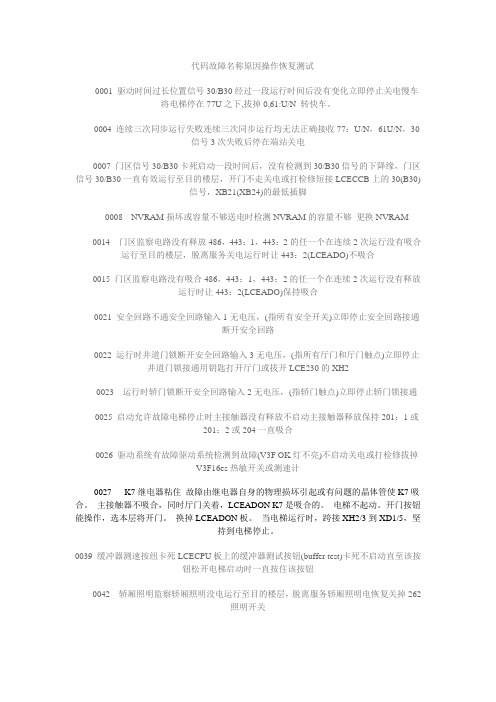
代码故障名称原因操作恢复测试0001 驱动时间过长位置信号30/B30经过一段运行时间后没有变化立即停止关电慢车将电梯停在77U之下,拔掉0,61:U/N 转快车。
0004 连续三次同步运行失败连续三次同步运行均无法正确接收77:U/N,61U/N,30信号3次失败后停在端站关电0007 门区信号30/B30卡死启动一段时间后,没有检测到30/B30信号的下降缘,门区信号30/B30一直有效运行至目的楼层,开门不走关电或打检修短接LCECCB上的30(B30)信号,XB21(XB24)的最低插脚0008 NVRAM损坏或容量不够送电时检测NVRAM的容量不够更换NVRAM0014 门区监察电路没有释放486,443:1,443:2的任一个在连续2次运行没有吸合运行至目的楼层,脱离服务关电运行时让443:2(LCEADO)不吸合0015 门区监察电路没有吸合486,443:1,443:2的任一个在连续2次运行没有释放运行时让443:2(LCEADO)保持吸合0021 安全回路不通安全回路输入1无电压,(指所有安全开关)立即停止安全回路接通断开安全回路0022 运行时井道门锁断开安全回路输入3无电压,(指所有厅门和厅门触点)立即停止井道门锁接通用钥匙打开厅门或拔开LCE230的XH20023 运行时轿门锁断开安全回路输入2无电压,(指轿门触点)立即停止轿门锁接通0025 启动允许故障电梯停止时主接触器没有释放不启动主接触器释放保持201:1或201:2或204一直吸合0026 驱动系统有故障驱动系统检测到故障(V3F OK灯不亮)不启动关电或打检修拔掉V3F16es热敏开关或测速计0027 K7继电器粘住故障由继电器自身的物理损坏引起或有问题的晶体管使K7吸合。
主接触器不吸合,同时厅门关着,LCEADON K7是吸合的。
电梯不起动。
开门按钮能操作,选本层将开门。
换掉LCEADON板。
当电梯运行时,跨接XH2/3到XD1/5,坚持到电梯停止。
电梯人员培训内容(二)

电梯人员培训内容(二)引言概述:
本文旨在探讨电梯人员培训的内容,以确保电梯工作人员具备必要的技能和知识,以保证电梯的安全和顺畅运行。
电梯人员培训内容主要包括五个大点,即电梯操作技能、安全意识培养、故障处理能力、紧急状况处理和顾客服务能力。
正文:
1. 电梯操作技能:
- 熟悉电梯的各种控制装置和操作方法。
- 掌握电梯的开停运行程序以及楼层选择和故障报警等操作。
- 学习正确的乘梯姿势和乘客引导技巧。
2. 安全意识培养:
- 了解电梯运行的基本原理和安全规定。
- 学习如何正确使用安全装置,如门锁、限速器和应急通讯设备。
- 掌握应急疏散程序和灾难事故处理的基本技巧。
3. 故障处理能力:
- 学习电梯常见故障的排查和处理方法。
- 掌握紧急停运和开启电源的操作流程。
- 熟悉电梯设备和部件的维护保养,以及常见故障的预防和处理。
4. 紧急状况处理:
- 学习在火灾、地震等紧急状况下的逃生和自救技巧。
- 掌握紧急救援程序,包括打开电梯门、协助乘客疏散等。
- 培养冷静应对突发状况的能力,保障乘客的安全。
5. 顾客服务能力:
- 培养良好的沟通技巧和服务意识,提高服务质量。
- 学习礼仪和职业道德,为乘客提供友好和专业的服务。
- 掌握处理乘客投诉和纠纷的解决方法。
总结:
通过本文的分析,我们了解了电梯人员培训的内容,包括电梯操作技能、安全意识培养、故障处理能力、紧急状况处理和顾客服务能力。
这些培训内容能够帮助电梯工作人员掌握必要的技能和知识,提高工作效率和服务质量,确保电梯的安全运行和乘客的舒适体验。
电梯规格表2

TOSHIBA ELCOSMO-E 后 客用电梯规格表<主要规格>电梯规格:L1-L2:P11 W( 825)-CO 60- 6S/ 6FL21-L26:P11 W( 825)-CO 105-17S/17FL27-L31:P14 W(1050)-CO 105- 9S/ 9FL3-L5:P11 W( 825)-CO 60- 9S/ 9FL6-L10:P11 W( 825)-CO 60-11S/11F对重位置:L1-L10,L21-L31:对重位置:后配重载重量:L1-L10,L21-L26:825公斤L27-L31:1050公斤速度:L1-L10:60米/分钟L21-L31:105米/分钟停层:L1-L2:6层6站L21-L26:17层17站L3-L5,L27-L31:9层9站L6-L10:11层11站楼层显示:L1-L2:1-6L21-L26:1-17L3-L5,L27-L31:1-9L6-L10:1-11拖动方式: 电脑控制无齿永磁同步电机控制方式: 变频、变压微电脑控制开门方式:L1-L10,L21-L31:中分门轿门尺寸:L1-L10,L21-L26:宽 800mm 高 2100mmL27-L31:宽 900mm 高 2100mm侯梯厅出入口尺寸:L1-L10,L21-L26:全层 宽 800mm 高 2100mmL27-L31:全层 宽 900mm 高 2100mm电源要求: 三相动力用380伏50赫兹、单相照明用220伏50赫兹 (电压正负误差7%以内)<土建要求>井道全高:L1-L2:20200mmL21-L26:53600mmL3-L5,L27-L31:29200mmL6-L10:35200mm升降行程:L1-L2:15000mmL21-L26:48000mmL3-L5,L27-L31:24000mmL6-L10:30000mm井道尺寸:L1-L10,L21-L26:1950mm × 1960mmL27-L31:2200mm × 2010mm底坑深度:L1-L10:1300mmL21-L31:1450mm以上尺寸为参考尺寸,实际尺寸以双方确认的图纸为准<规格说明>一、轿厢(1)轿厢尺寸:L1-L10,L21-L26:1400mm × 1350mm × 2300mmL27-L31:1600mm × 1400mm × 2300mm(2)轿壁:L1-L10,L21-L31:三侧轿壁材质:发纹不锈钢,前轿壁材质:发纹不锈钢,轿厢幕板:发纹不锈钢(3)轿门:L1-L10,L21-L31:轿门材质:发纹不锈钢(4)轿顶:L1-L10,L21-L31:轿厢照明:SL-4图案,附照明设备(5)通风: 换气扇(6)轿厢内操作盘:L1-L10,L21-L31:轿厢操作盘:无(A): 一个以钥匙操作之开关箱内有照明开关、风扇开关(B): 上升与下降方向指示(C): 具有与停靠层同数之微触式楼层按钮(D): 开门及关门微触式按钮各一付,并以图形表示(E): 操作盘面板上端附有禁烟标识(F): 数字型楼层指示器(G): 标示厂牌(TOSHIBA),用途、乘人数、限载重量(H): 隐蔽式对讲机一付(I): 黄色紧急呼叫按钮(ALARM)(7)地槛:L1-L10,L21-L31:轿厢地坎:铝(8)踢脚板材质:L1-L10,L21-L31:踢脚板材质:无(9)地板:L1-L10,L21-L31: 轿厢地板颜色:MID833 轿厢地板材质:2mm塑胶地砖二、各楼层出入口(1)厅门:L1-L2:2-6层 厅门材质:钢板涂装 1层 厅门材质:SUS发纹L21-L26:2-17层 厅门材质:钢板涂装 1层 厅门材质:SUS发纹L3-L5,L27-L31:2-9层 厅门材质:钢板涂装 1层 厅门材质:SUS发纹L6-L10:2-11层 厅门材质:钢板涂装 1层 厅门材质:SUS发纹(2)门套:L1-L2:2-6层 小门套:钢板涂装 1层 小门套:发纹不锈钢L21-L26:2-17层 小门套:钢板涂装 1层 小门套:发纹不锈钢L3-L5,L27-L31:2-9层 小门套:钢板涂装 1层 小门套:发纹不锈钢L6-L10:2-11层 小门套:钢板涂装 1层 小门套:发纹不锈钢(3)召唤按钮及位置指示: 各层采用直式数位指示器,附微动式按钮三、基本功能(1)集选全自动方式(2)故障时自动就近平层(3)自动脱离联动控制(4)检修运行(轿顶、机房)(INS)(5)超载保护示警(6)上行超速保护(7)下行超速保护(8)火灾管制运行A(9)轿内管制运行表示灯(10)轿内应急照明(11)紧急电动救援运行(HRQ)(12)抱闸动作检测反馈(13)轿内紧急呼叫装置(14)马达空转保护(15)门区内自动再平层(16)脉冲位置异常时自动校正(17)复电后自动运行(18)故障低速自救运行功能(19)钢丝绳拉伸自动补偿功能(20)驱动系统温度异常检知保护(21)楼高尺寸自动记忆调整功能(22)管制运行迫降反馈信号(REH)(23)纯光幕(无安全触板)(24)宽电压接入保护(25)满员自动通过功能(26)轿厢内误召唤取消(手动)(27)取消轿内恶作剧功能(>5层站,轿内重量<150kg)(28)运行次数存储(29)故障自动记忆功能(30)异常时梯门反复开关(31)开门时间自动设定(32)电子称重补偿启动(33)换向重开门(34)即时关门(35)驻停功能(36)照明自动关闭功能功能(37)换气扇自动停止功能(38)五方通话系统(39)自动反回基站(40)轿内层站方向显示(41)开门按钮灯(轿内自动熄灭灯时)四、附加功能(1)L1-L10,L21-L31:火灾管制运转:火灾管制运行方式B(国内适用)(2)L1-L2,L6-L10,L21-L31:火灾管制运转避难层:1(3)L1-L2,L6-L10,L21-L31:消防人员运转层:1(4)L1-L10,L21-L31:轿厢总加重:3。
OTIS GeN2电梯钢带报废标准

精心整理
OTISGeN2电梯钢带报废标准
本标准定义了OTISGeN2电梯曳引用钢带的报废基本标准。
1钢带的设计寿命为20年,是传统钢丝绳寿命的2~3倍,在钢带的设计寿命周期内推荐对钢带进行至少每年一次的全面外观检查。
2钢带的外包覆层与包覆层内的钢芯在使用中无任何磨损或损坏痕迹且钢带实时监测报警装置无异常报警时,钢带使用周期满20年后,建议报废更换,如需继续使用,应加强对钢带的定期例行检查。
3在例行保养中如发现钢带实时监测报警装置有异常报警但未停梯时,应确认钢带监测报警装置是否有异常,如钢带报警装置本身无异常,应立即准备报废更换钢带。
4如钢带实时监测报警装置报警并就进停梯时,电梯不得以任何方式重新服务,应立即报废更5在用的电梯钢带有以下图示情形之一的应该进行强制报废更换。
钢芯从外层包裹材料中裂出
外表面可见明显的钢芯痕迹
外表面有明显可见的压痕
钢丝穿出表面
成块的表面被磨光
钢带边缘有较长的微小裂纹
表面有可见的长裂纹
表面有可见的长裂纹
6如果一根钢带需要报废更换,则该台电梯所有其它钢带也需要被同时报废更换。
钢带应避免长时间完全暴露在高温(大于50摄氏度)环境下或处于阳光暴晒的环境中,如果出现上述情形,需征询相关钢带专家的意见,情况严重时,应报废处理。
日立GVF2电梯FMT板说明及故障代码
日立GVF2电梯FMT板说明及故障代码NPH GVF2的FMT板操作说明MODE-0-SET 显示楼层MODE-1-SET 显示状态MODE-2-SET 故障码读取MODE-3-SET 机房检修MODE-4-SET 故障清除MODE-11-SET 层高测试GVF GH98 GVF2 NPH的故障码说明E10—E27 A1 停止电梯所有运作功能(*1)E30—E47 A2 停止电梯所有快、慢车运行功能(*2)E50—E57 B1 停止电梯快车、部分慢车运行功能(*3)E60—E67 B2 停止电梯快车运行功能(*4)E70—E77 C2 使电梯运行至最近指令层停车,然后按A2级故障方式处理E80—E87 E 对故障不作处理备注:(1)当电梯同时出现2个以上的故障时,故障的处理级别按高的进行。
(2)当电梯发生A、B类故障时,软件回路安全继电器#50X、运行接触器#10T和抱闸接触器#15B立即释放,电梯数字显示立即熄灭。
如果电梯发生故障是A2、B1或B2级时,软件回路安全继电器#50X在释放3秒钟后会再次吸合,这时电梯数字显示也恢复正常。
(3)在电梯的这6种级别的故障中,其中A1级故障是具有自动保持性质的。
也就是说当使电梯发生A1级故障的原因被排除或消除后,会继续保持A1级的处理状态,不会自动解除故障状态重新投入正常运行。
而其它级别的故障在故障条件排除或消除后,可以自动使电梯恢复正常运行状态。
*1.当A1级故障条件成立时,FMT微机使电梯进入A1级故障处理的状态—停止电梯所有运作功能。
所停止运作功能包括:电梯快车运行方式、慢车运行方式、电梯开关门功能、电梯显示等功能。
*2.A2级故障处理时,电梯停止快、慢车运行方式,但如果电梯是在门区位置时,可以开门。
*3.B1级故障处理时,电梯停止快车运行方式,只能作自救的慢车运行方式。
*4.B2级故障处理时,电梯停止快车运行方式,可作任何慢车运行方式。
E11 #10T ON、OFF故障E12 #15B ON、OFF故障E14 #97输入信号异常E21 #11输入信号异常E22 #12输入信号异常E26 规格表和数出错E27 重复故障检出E31 #100R输入信号异常E32 门区感应器故障E33 变频器异常运行E35 厅门、轿门动作不一致E36 变频器运行故障E37 电梯逆转故障E40 零速不一致E41 电梯低速超速故障E42 软安全回路继电器ON、OFF故障E43 变频器控制回路失电故障E44 #11动作超时故障E45 #12动作超时故障E46 速度低故障E50 高速超速故障E51 起动速度控制异常E52 瞬时停电故障E53 运行速度偏差故障E55 中速超速故障E56 微动平层超速故障E57 微动平层运行距离异常E60 电梯层高表和数出错E61 电梯同步位置出错E62 电梯层楼位置出错E63 电梯端站位置出错E64 电梯端站减速控制异常E70 变频器故障报警检出E71 变频门机故障E73 门区运行故障E75 通讯检出故障E76 电梯爬行时间异常E77 自救检出故障E80 电梯运行中断门锁检出E81 电梯检修状态异常E82 电梯微动平层超时故障E83 电梯安全回路故障检出E84 微动平层起动故障E85 变频器速度一致信号异常E86 电梯开门超时故障E87 电梯关门超时故障。
淩云2电梯主板开关说明
淩云2电梯主板开关说明
将凌云电梯控制柜操作板上开关朝上,此时为机房检修状态。
(开关朝下为正常状态)
再将主板上开关(S9)朝上或朝下按住不放,电梯将以检修速度向上或向下运行。
故障清除操作:
显示器上显示EE表示有故障记录,保养时需要清除,否则将出现故障记录过多而保护死机。
此时将主电源关闭,按住主板上4号键不放再送电,一般情况下可复位,若不能复位就要作故障清除,方法如下:
按主板上1号键2下显示00。
按主板上2号键n下使显示器显示0E。
按主板上3号键1下显示E0。
按主板上2号键1下使显示器显示E1。
按主板上3号键1下,再按2号键1下显示E0。
按主板上2号键2下使显示器显示E2。
按主板上3号键1下显示0E。
按主板上4号键强制返回,故障清除操作结束。
注:操作板上9号键是故障记录开关,正常时开关朝上,否则故障记录很快将出现保护死机。
短接安全回路操作
当显示FD时表示安全回路断开,此时安全继电器CC断开、操作板上面的那个指示灯熄灭,首先检查安全回路供电保险管1F1(控制柜后面下排左起第6个)是否熔断;检修需要短接时,请用下列方法:
操作板上A2—A7短接:轿顶急停开关、轿内急停开关、安全钳开关。
操作板上A7—A10短接:上下极限开关、缓冲器开关、涨紧开关。
操作板上A10—A11短接:限速器开关。
TSG-T7001-2019第2号修改单电梯监督检验和定期检验规则
TSG 特种设备安全技术规范TSG T7001—2009电梯监督检验和定期检验规则——曳引与强制驱动电梯Regulation for Lift Supervisory Inspection and Periodical Inspection-Traction and Positive Drive Lift中华人民共和国国家质量监督检验检疫总局颁布2009年12月4日再版说明2017 年6 月12 日,国家质检总局以《关于发布<电梯监督检验和定期检验规则——曳引与强制驱动电梯>等6 个安全技术规范第2 号修改单的公告》(2017 年第44号),批准对《电梯监督检验和定期检验规则——曳引与强制驱动电梯》(TSG T7001—2009,含第1 号修改单)修改,重新印制。
现《电梯监督检验和定期检验规则——曳引与强制驱动电梯》(TSG T7001—2009,特种设备安全技术规范TSG T7001—2009前言2004 年5 月,国家质量监督检验检疫总局(以下简称国家质检总局)特种设备安全监察局(以下简称特种设备局)向中国特种设备检测研究院(以下简称中国特检院) 下达了本规则的起草任务书。
2004 年5 月,中国特检院组织有关专家成立起草组并在北京召开首次编制工作会议。
2005 年至2008 年,起草组召开了多次编制修订工作会议,提出修改意见,形成征求意见稿。
2009 年2 月,根据5 个省(直辖市、自治区)试用情况,起草组在北京召开会议,对试用反馈意见进行了整理,对本规则进行了进一步完善。
2009 年5 月国家质检总局以质检特函〔2009〕24 号文征求基层、有关部门、单位和专家及公民的意见。
2009 年8 月,根据征求到的意见和审议反馈的意见,起草组在北京召开会议,对规则进行了修改并形成报批稿,2009 年12 月4 日,由国家质检总局批准颁布。
本规则的编制工作,遵循了在满足国家有关法律、法规要求的前提下,兼顾我国电梯相关工作现状的原则。
Harmony系列2家用电梯用户手册说明书
USER MANUAL Harmony Series 2 Homelift Through Floor LiftOriginal instructionsCONTENTSIntroduction4 Description5 General Do’s and Don’ts6 Controls and Operation8 Smoke Alarms10 Emergency Procedures12 Fault Finding14 Changing Smoke Alarm Batteries16 Changing Call Station Batteries17 Safety Feature Check1819 Lift Disassembly / Safe Disposal of Hazardous MaterialsService History Record20 Declaration of Conformity21 Lift Specification Sheet22INTRODUCTIONThank you for choosing the Harmony Lift, designed and manufactured in the U.K. using the latest technology by Terry Group Ltd. We want you to get the most out of your Harmony Lift and to help in this aim we have produced this small booklet on operation and maintenance of the equipment, which we hope you will find helpful.It is hoped that any queries you may have during day to day operation will be answered in the text, but if you do have any problems, technical assistance is only a phone call away.We hope our product gives you many years of reliable service. Peter MorreyManaging DirectorDESCRIPTIONThe Harmony Homelift ‘N’ is an inter floor lift that is designed for use by persons with impaired mobility travelling between fixed floor levels in private dwellings.With a maximum carrying capacity of one person, with or without a wheelchair, this lift is not intended for use as a means of transporting goods.The lift is designed to operate without a lift shaft and is provided with an automatic infill panel which makes the ceiling aperture safe when the lift is parked downstairs.An optional telephone can be supplied in the car for emergency communication.A standard feature is the provision of half hour fire rated panels in both the aperture infill and the car underpan.The lift car panels are made from powder coated steel which can easily be cleaned using normal household cleaners. Upholstery is made from PVC and can be cleaned in the same way.A smoke detection system has been installed on your lift. It has been designed to provide adherence to British Standard BS5900 2012 Section 9.13 “Behaviour of homelift in the event of fire”.GENERAL DO’S AND DON’TS• Never switch off the power supply to the lift, even when you go away. The lift control circuits are fed by a battery, which must be kept on constant charge.• The lift should always be returned to the lower level when not in use. Ifit is left upstairs for prolonged periods, it will occasionally re-level itself depending on conditions. The lift must be left at the lower level if the mains is turned off.• If your lift is fitted with a manual door always close it after use. Powered door units have a self closer. Do not pull or push the automatic door.• Never allow children to play in, under or around the lift. If children are in the house, isolate the lift using the optional remote control fob, see pg 8.• Ensure that the area under the lift is kept clear. The underpan surface is fitted with sensors, which automatically stop the lift if it strikes an object (see Fig.1).• Always keep your emergency door release key and key fob in the lift or in a safe place near the lift.• Do not place any object on the aperture infill or stand on it when thelift is in operation. Ensure that as far as practical, the area around the travelling infill panel is clear of persons (particularly children) when the lift is being operated. This is to ensure there is no danger of them falling into the car when the lift is in use. The infill panel is fitted with sensors that automatically stop the lift if the infill panel is obstructed (see Fig.1)• Do not use this lift for anything other than transporting those with impaired mobility between fixed floor levels• Do not lean over the car sides or door. These are fitted with safety edges which will stop the lift if activated.• Always treat your lift with respect that should be shown to electrical and mechanical equipment.• Users with wheelchairs should apply the brakes on their chair and all other users should ensure they are using the seat provided before moving the lift. Do not travel in the lift unless seated.• Safety related components should only be adjusted and reset by a competent person.Proceed with caution when exiting the carriage backwards The diagram below (Fig.1) shows the position of all the sensors on the lift, designed to prevent injury or damage if the movement of the carriage is obstructed.Infil panel safe edge(sensors on upperand lower surfaces)Safe edges(sensor on lower and upper surface)Fig. 1Harmony lift shown part-waythrough apertureCONTROLS AND OPERATIONThere are two wall mounted call stations, one at each level (see Fig.2) and a similar control station fitted in the lift car. The lift can be isolated by using the optional remote control fob. When the lift is isolated, none of the control stations will function. The call and control stations can only be activated by using the remote fob. When the lift is activated, the coloured indicator lights in the car will illuminate. The lights in the car will switch on automatically when any call or control button is pressed and will automatically turn off after a few minutes.Once the lift has been stopped it cannot be restarted for 3 seconds.Users with wheelchairs should apply the brakes on their chair and all other users should ensure they are using the seat provided before starting the lift.DOWNDOORSTOPUPWall mounted call station Optional remoteisolate fob Fig. 2General operation Call the lift by pressing the UP or DOWN button on either call station and wait for it to stop. The door will automatically open. Enter the lift and press and release the door button to close it. Then press and release UP or DOWN on the control station. The lift will travel uninterrupted to the next floor. If the lift does not start, check that the door is properly closed and try again. Always close the door after using the lift by pressing the DOOR button on the wall mounted call station. The lift should always be returned to the lower level when not in use.In the event that the normal controls fail to work, emergency controls can be found under the flap above the mirror. Green is ‘UP’, red is ‘STOP’, black is ‘DOWN’ and white is ‘DOOR’. See Fig.3When outside the car, in an emergency the door can be opened by pressing the front end of the side safe edge, on the corner where the door opens (See Fig.3a).Fig. 3Fig. 3aSMOKE ALARMA smoke detection system has been installed on your lift. It has been designed to provide adherence to British Standard BS5900 2012 Section 9.13 “Behaviour of homelift in the event of fire”.The system utilises two smoke alarms one upper level, one lower level, which are wirelessly connected to the main circuit board on the lift (see illustration below).The Smoke Alarm unit comprises two parts, the first (TOP PART) being a Smoke alarm unit. This is the Smoke detection unit and contains an integral battery with a 10 year life span. This is not replaceable.The second part (BASE UNIT) contains the radio transmitter receiver unit. Power to this unit is supplied by two AA styleLithium batteries. The voltage level of the batteries is monitored. In the event of a low battery, a sounder in the carriage will beep (see Fault Finding pg.14). If the batteries are not replaced, the lift will be taken out of service.Radio smoke alarm operation When installed on a Harmony Lift, the smoke alarm system will cause the lift to deactivate safely once the alarm is triggered. When deactivated, the door will continue to operate as normal.Mute/test buttonSmoke Alarm (TOP PART)Radio Transmitter/receiverUnit (BASE UNIT)When the Lift is stationary at either level:If smoke is detected, the alarm will sound. After a period of time, all other smoke alarms connected to the system will then start to sound and the lift deactivates.When the Lift is travelling between levels:If smoke is detected, the alarm will sound. After a period of time, all other smoke alarms connected to the system will then start to sound.The lift will continue to its requested level, it will remain possible (until that level is reached) to change the direction of the lift. Once at the desired level, the lift will deactivate.Reactivation of LiftThe lift will automatically reactivate when the smoke alarm no longer detects smoke and a period of two minutes has expired. Silencing the Smoke AlarmsIn either situation, it is possible that the sounder of each individual alarm can be silenced. The alarms that has been set off remotely can be silenced by pressing the both the STOP and DOOR button on one of the lift handsets. Then the alarm that has been triggered by the smoke can be silenced by pressing the mute button on the alarm itself. Doing this will silence the alarms for four minutes. When silenced, the lift will automatically reactivate when a period of two minutes has expired. If the source of smoke is not removed, the smoke alarms will begin to sound again and the lift will be disabled.EMERGENCY PROCEDURESIn the event of a mains failure during travel, the battery backed control system of the Harmony will allow normal operation in the down direction without loss of any safety features. This allows the user to exit the car at the lower level in the normal way.Emergency Manual LoweringIMPORTANT:During emergency manual lowering, the normal safety features will not function, so the lift will not stop if a person, pet or object is under the lift.• The exact lowering procedure must be observed, because the normal safety features will not function during manual lowering.• The emergency lowering procedures should never be used if the lift is fully up or no one is trapped in it.• The emergency lowering procedures should also never be used as the normal down travel function until an engineer attends.PLEASE NOTE:If the lift is fully upstairs and a person is trapped inside, please see the section Emergency unlocking (see pg13).If the lift has stopped mid level and the customer is unable to get the lift up or down then the only time it should be lowered by the emergency valve is if:• There is a second person (B) around the lift area at the lower level to ensure that nothing goes under the lift during the lowering by the first person (A);• OR the person lowering the lift has sight of the area under the lift . Person A• Ensure the door is fully closed.• Turn the mains supply to the lift off.• Locate the hydraulic power unit, normally outside the property (see Fig. 4).• Swivel the small metal cover plate on the front face of the housing to reveal an access hole (see Fig. 4).• The red cord revealed in the access hole now needs to be pulled continuously to lower the lift car slowly.• After 5 seconds release button and check with person B that the trap door is following the carriage. If so continue to lower • Once the lift is at the lower level turn the mains supply back on.Person BRemains in the house by the lift and communicates with Person A to ensure the safe lowering of the lift.• Ensure that no object, person or pet are in the path of the lift travel • Confirms that the trap door follows the lift during descent and locates fully in the floor to guard against the possibility of anyone falling down the lift way.Emergency unlockingWARNING: RISK OF FALLING – Emergency unlocking must only be undertaken when the lift is at the upper or lower landing level.The lift car door is designed so that it will only open when the lift is at or within 25mm of each floor served. If for any reason the door cannot be opened, the door lock can be over-ridden from the inside using the following steps:• Remove the black rubber grommet by the door.• Insert the black emergency door release key into the square hole behind the grommet.•Turn the key to release the mechanism.This should release the catch. The door can be opened from the outside in the same way.The electrically operated door on the wheelchair model can be forced open or closed manually. This will disengage the door from the opening mechanism and require re-setting of the door. Re-setting of the door can be done as follows:lowering string behind the plate.Indicates mains power to lift (usually ‘on’ red).Fig. 4Battery warning (red) This is normally off, but may be on during operation.This is OK providing it extinguishes eventually when lift is at either levelDOWN CAR (yellow light). Means safe edge car OK. Will be off when ascending and when at UP CAR (green light)Means safe edge car OK. Will be off when descending.DOWN TRAP (yellow light). Means safe edge in fill panel OK. Will be off when ascending.UP TRAP (green light)Means safe edge infill panel OK. Will be off when descending.Fig. 5• Manually close the door as far as possible.• Press and release the door button.• Move the door back and forth until it clicks.• Press and release the door button again.The door should now operate normally, otherwise repeat the above process.FAULT FINDINGThe most likely causes of your lift failing to operate are:•No mains power supply• The door not being fully closed.• Something obstructing the travel of the car or in fill panelcausing one or more of the sensors or safe edges (see Fig.1) to operate and therefore preventing travel in the appropriate direction.To assist in identifying the cause the car if fitted with a simplesystem of coloured indicator lights on the rear panel, one red, two yellow and two green (see Fig.5).Lift MalfunctionFault Indication Cause RemedyNo lift function at all.No red LED onpowerpack cover.No mains power tothe lift.Check mains is onand reset RCD/Spurif required.Lift will not travel in either direction.No lights on carpanel.Door not shut orremote fob off.Press door buttonPress button on fob.Flat batteries insmoke alarms.Replace smokealarm batteries.Lift will not go up.One green off oncar panel.Car safe edgeobstruction.Remove obstructionor free safe edge.Both greens off on car panel.Infill panel obstructedon upper surface.Remove obstructionfrom upper surface.Lift will not go down.One yellow off oncar panel.Car underpanobstruction.Remove obstructionfrom beneathsurface.Both yellow off on car panel.Infill panel obstructedon lower surface.Remove obstructionfrom lower surface.Powered door will not close fully.Can be movedeasily by hand.Door has disengagedfrom drivemechanism.See pg 13 & 14Person B emergencyunlocking.Smoke Alarm MalfunctionIndication Cause Remedy Alarm beeps twice every 45 seconds.Unit Malfunction.Call an engineer.Alarm does not sound upon pressing testbutton.Unit Malfunction.Call an engineer.The operating light remains steadily on or off(ie. Does not flash approximately once every 45seconds when unit not in alarm).Unit Malfunction.Call an engineer.Low Battery WarningIndication Cause Remedy Single short beep on lift car every 2 minutes.Low Handset battery.Replace CR2450batteries in handset.Double short beep on lift car every 2 minutes.Low smoke alarmbattery.Replace AA batteries in smoke alarm.Double long beep on lift car every 2 minutes.Smoke alarm batterydangerously low.Replace AA batteries in smoke alarm.Lift will not travel in either direction.Smoke alarmbatteries flat.Replace AA batteries in smoke alarm.CHANGING SMOKE ALARM BATTERIES1. To change the batteries push upwardson this part of the alarm base with anysmall tool, then turn alarm clockwise.2. Unscrew the alarm base plate fromthe box3. Fit the two AA style Lithiumbatteries into the board batteryholder as shown.CHANGING CALL STATION BATTERIES CR2450 (550 mAh minimum) are approved for use with these devices.CRITICAL:• It is critical that all three batteries are replaced with new ones of the same type, manufacture and age, that they are fitted at the same time and that they are correctly oriented.1. The call station can beremoved from the wall bysliding the case upwards.2. Remove the four screws inthe back with a posi-drivescrewdriver.3. Using a screw driver, gentlypush the battery out a shortway and then pull usingfingers.SAFETY FEATURE CHECKSAS A PRECAUTIONARY MEASURE WE ADVISE PERIODIC (WEEKLY) CHECKS OF THE SAFETY FEATURES BUILT INTO YOUR HARMONY INTER FLOOR LIFT AS FOLLOWS:-(see Fig.1)1 CARRIAGE SIDES AND DOOR UPPER SAFE EDGEWith the lift at lower level, press the UP button on the wallstation, when lift starts to ascend press downwards oncarriage side upper surface, the lift should stop.Lower the lift to floor level and repeat operation with othercarriage side and door.2. CARRIAGE UNDERFLOOR SAFETY UNDERPANWith the lift at approximately eye level press the DOWNbutton on wall station, when lift starts to descend pressupwards on the carriage underpan, the lift should stop.Raise lift and if possible, repeat operation on oppositeside of lift.THESE CHECKS SHOULD BE CARRIED OUT WITH THE LIFT UNOCCUPIEDIf any of the above checks fail, the lift MUST NOT be used and advice sought from Terry Group Ltd.Servicing & MaintenanceThis lift should be serviced at least every 12 months. This service should be conducted by competent persons trained in servicing and repair of the product.Lift Disassembly/Safe Disposal ofHazardous MaterialsThis lift must be disassembled by a competent person who has been fully trained in the installation of this lift and is qualified to provide safe disconnection of the lift to the mains terminal. Batteries & Printed Circuit Boards (PCB)The batteries and PCB’s within this product should not be disposed of with other household waste at the end of their working life. Where batteries are marked with the chemical symbols Hg, Cd or Pb, it indicates that the battery contains mercury, cadmium or lead above the reference levels in EC Directive 2006/66. If batteries are not properly disposed of, these substances can cause harm to human health or the environment. Batteries and PCB’s that are no longer required for this lift, at the end of their working life, can be returned either to an approved waste disposal facility or to Terry Group Ltd for safe disposal.OilOil from this lift should be disposed of via an authorised waste disposal contractor or to an approved waste disposal facility.SERVICE HISTORY RECORDAn entry should be added to the following table every time the lift is serviced.Date Engineer Company CommentsLift Type: Harmony LiftThis lift was manufactured by TERRY GROUP Ltd., who declare that this lift fulfils all the relevant provisions of the following Directives:2004/108/EEC Electromagnetic Compatibility Directive2006/42/EC Machinery DirectiveThis lift also fulfils all the relevant provisions of the following Standards:BSEN 12015:2014Electromagnetic compatibility. Product familystandard for lifts, escalators and moving walks.Emission.BSEN 12016:2013Electromagnetic compatibility. Product familystandard for lifts, escalators and moving walks.Immunity.BS5900:2012Powered homelifts with partially enclosedcarriers and no liftway enclosures – Specification Person authorised to compile Technical File:Greg Gnyp, Terry Group Ltd., Longridge Trading Est, Knutsford, Cheshire, WA16 8PR. EC examination carried out by: Bureau Veritas UK Ltd., Parklands, Wilmslow Road, Didsbury, Manchester, M20 2RE.Notified Body Reference Number:0041EC examination certificate number: CE-0041-MD-TER001-10-GBRThis declaration was completed at Terry Group Ltd., Longridge Trading Estate, Knutsford, Cheshire, WA16 8PR, in August 2014.This compliance is only valid if the installation test Certificate has been completed and signed by a competent lift engineer trained to install this product to the latest installation instructions.TERRY GROUP Ltd.LIFT SPECIFICATIONAddress of manufacturer:-Terry Group Ltd.,Unit 1 Longridge TradingEstate,Knutsford,Cheshire,England,WA16 8PR.Lift serial No: Year of manufacture:Safe working load:Harmony S & W = 280kgHarmony L & LW = 250kg Maximum travel: 3.6 metresDuty cycle:10 cycles per hr with max load Average noise level:65 dBPower supply:Dedicated 240V ~ 50/60 Hzsingle phase supplyControl voltage:12V DC1200W maximumHydraulic pump powerconsumption:Hydraulic oil grade:T22Hydraulic pump enclosure:IP54Designed and manufacturedBS5900:2012to:Fire specification:Half hour fire integrity throughaperture, Exova Warrington FireResearch assessmentNo. 32092524For technical help,sales or service enquiry telephone:This Harmony Lift has been manufactured by:Terry Group Ltd.Longridge Trading Estate,Knutsford, Cheshire, WA16 8PR.t************e:*******************.ukw: Certificate Number 13858ISO 9001, ISO 14001,OHSAS 18001。
电梯自检自查报告(二)2024
电梯自检自查报告(二)引言概述:电梯自检自查报告(二)旨在对电梯设备进行维护和保养,并确保其正常运行和安全性。
本报告将详细介绍电梯自检自查的过程和结果,以及针对电梯各方面的问题和解决方案。
正文:一、电梯外观检查1. 检查电梯门是否完好并且无损伤。
2. 检查电梯井道内外壁面是否存在腐蚀或损坏。
3. 检查电梯门轨道和滑轮系统是否正常运行。
4. 检查电梯标志和安全告示是否清晰可见。
5. 检查电梯照明是否正常工作。
二、电梯控制系统检查1. 检查电梯按钮是否灵敏,是否存在松动或缺损。
2. 检查电梯内外呼梯系统是否正常运行。
3. 检查电梯运行指示灯和显示屏是否正常工作。
4. 检查电梯停靠层是否准确和稳定。
5. 检查电梯异味和异常噪音是否存在。
三、电梯传动系统检查1. 检查电梯驱动单元是否正常工作。
2. 检查电梯钢索和平衡重是否处于适当的位置和状态。
3. 检查电梯制动装置是否可靠,并确保其正常工作。
4. 检查电梯缓冲装置是否符合安全标准。
5. 检查电梯轿厢和井道之间的间隙和对齐度。
四、电梯安全系统检查1. 检查电梯报警装置和紧急通信设备是否可用。
2. 检查电梯门情况是否符合安全要求。
3. 检查电梯紧急停机装置是否正常工作。
4. 检查电梯疏散通道和疏散指示是否明确。
5. 检查电梯火灾探测器和灭火装置是否有效。
五、电梯日常维护和保养1. 定期清洁电梯内部和外部。
2. 定期润滑电梯传动系统和轴承。
3. 定期检查电梯电气系统和线路连接。
4. 定期检查电梯机房和设备的通风和冷却系统。
5. 定期维护电梯门系统,确保其正常运行。
总结:通过对电梯自检自查的全面评估和维护,可以确保电梯设备的正常运行和安全性。
本报告介绍了五个主要检查方面,覆盖了电梯的外观、控制系统、传动系统、安全系统以及日常维护和保养。
我们将根据报告结果采取相应的解决方案,确保电梯设备在日常使用中的安全和可靠性。
- 1、下载文档前请自行甄别文档内容的完整性,平台不提供额外的编辑、内容补充、找答案等附加服务。
- 2、"仅部分预览"的文档,不可在线预览部分如存在完整性等问题,可反馈申请退款(可完整预览的文档不适用该条件!)。
- 3、如文档侵犯您的权益,请联系客服反馈,我们会尽快为您处理(人工客服工作时间:9:00-18:30)。
7 (d)控制电梯是一种自动控制程度较高的有司机操作的电梯。
A、机械;B、电气;C、人工;D、信号
8 (d)叫液压电梯。
A、提升绳靠主机的驱动轮绳槽的摩擦力驱动的电梯;
B、用链或钢丝绳悬吊的非摩擦方式驱动的电梯;
C、其轿厢适用于运载私人汽车的电梯
D、以液体的压力为动力源,通过柱塞直接或间接地作用于电梯的轿厢,轿
厢在固定的导轨之间运行
2 (d)的作用是使绳与绳轮之间具有足够的压紧力,使绳轮能准确反映电梯运
行速度。
A、限速器;B、 限速器超速开关;C、限速器绳;D、张紧装
置
3 (b)是轿厢无指令运行时停靠的层站,一般位于大厅或底层端站乘客最多的
地方。
A、层站;B、基站C、顶层端站;D、底层端站
5 (c)是安装在轿厢顶部的控制面板。当它启动时,轿厢将脱离正常的操作而
只受它控制在检修的速度下运行。
A、机房;B、继电器;C、轿顶检修盒;D、轿厢操纵盘
(d)是曳引式电梯用于挂绕曳引绳的有槽的轮子,轿厢和对重的运动就是通
过它由曳引钢丝绳带动。
A、限速器;B、 限速器超速开关;C、曳引机;D、 曳引轮
8 (a)是各楼层用于出入轿厢的地点。
A、层站;B、基站C、顶层端站;D、底层端站
9 (c)是任何一种机械的,用于防止在电梯厅门外打开厅门的锁。
A、控制柜;B、 门机;C、门锁;D、平层
10 (c)有两种形式,一种是机械式的,它是通过钢丝绳及滚轮拉动开关,断
开总电源;另一种是与减速、限位开关结构相同的极限开关,动作时,切断上、
下接触电源,使电梯停止运行。
A、端站减速安全保护;B、端站限位安全保护;C、端站极限开关
保护;D、越程安全保护装置
1 (a)是在电梯井道的顶层和底层,当电梯运行到减速位置时,应立即换(减)
速,切断高速,以免造成冲顶或墩底。
A、端站减速安全保护;B、端站限位安全保护;C、端站极限开关
保护;D、越程安全保护装置
2 (b)是安装于轿厢上由马达驱动门开或门关的装置。
A、控制柜;B、 门机;C、门锁;D、平层
3 (d)位于行程端部,用来吸收轿厢动能的一种弹性缓冲安全装置。
A、位置显示装置;B、选层器;C、限速器;D、缓冲器
6 (d)是曳引式电梯用于挂绕曳引绳的有槽的轮子,轿厢和对重的运动就是通
过它由曳引钢丝绳带动。
A、限速器;B、 限速器超速开关;C、曳引机;D、 曳引轮
7 (a)叫曳引驱动电梯。
A、提升绳靠主机的驱动轮绳槽的摩擦力驱动的电梯;
B、用链或钢丝绳悬吊的非摩擦方式驱动的电梯;
C、其轿厢适用于运载私人汽车的电梯
D、以液体的压力为动力源,通过柱塞直接或间接地作用于电梯的轿厢,轿
厢在固定的导轨之间运行
9 (d)是设置在轿厢内的一块用于操纵电梯的面板。上有楼层选择按钮,开门
和关门按钮,警铃按钮以及其它需要用于操纵电梯的开关或按钮。
A、机房;B、继电器;C、轿顶检修盒;D、轿厢操纵盘
3 (a)是轿厢内和厅门的指示灯,以灯光数字显示电梯所在的楼层,以箭头显
示电梯的运行方向。
A、位置显示装置;B、选层器;C、限速器;D、缓冲器
6 (b),方便维修人员在底坑检修电梯时停止电梯运行,以防止出现误动作伤
人。
A、检修运行开关;B、底坑停止开关;C、过载及短路保护装置;
D、直流电动机的弱磁保
10 (d)是当电梯在平层区域向厅门地坎接近的动作。是指完全自动地到达一
层或一个停车位置(轿底平面与厅门地坎平齐)的一个过程。
A、控制柜;B、 门机;C、门锁;D、平层
1 (b)是由上、下限位开关组成,如果减速开关未起作用,限位开关则动作,
使电梯停止,切断方向接触器或方向继电器。A、端站减速安全保护;B、
端站限位安全保护;
C、端站极限开关保护;D、越程安全保护装置
2 《特种设备安全监察条例》规定:特种设备包括其所用的材料、附属的安全
附件、安全保护装置和与安全保护装置相关的设施。(a )
A、正确;B、错误
5 并联或群控控制的电梯轿厢无运行指令时,指定停靠待命运行的层站,称为
(c)。
A、基站;B、底层端站;C、预定基站;D、顶层端站
10 (d)是一种表面经过机械加工的T形的钢轨,竖直地安装在井道中,用于
电梯轿厢或对重的运动导向。
A、抱闸;B、抱闸靴;C、导轨;D、导轮
2 (b),方便维修人员在底坑检修电梯时停止电梯运行,以防止出现误动作伤
人。
A、检修运行开关;B、底坑停止开关;C、过载及短路保护装置;D、
直流电动机的弱磁保护
3 (a)用于检修,或在电梯故障后,将电梯开到平层位置的开门装置。
A、检修运行开关;B、底坑停止开关;C、过载及短路保护装置;D、
直流电动机的弱磁保护
4 并联或群控控制的电梯轿厢无运行指令时,指定停靠待命运行的层站,称为
(c)。
A、基站;B、底层端站;C、预定基站;D、顶层端站
5 (b)是服务于规定楼层的固定式升降设备。它具有一具轿厢,就其尺寸和结
构型式而言,轿厢内不允许进人。