安装说明书
平板型爆破片安装使用说明书

上海朗晏安全系统设备有限公司平板型爆破片装置安装说明书安装前应仔细阅读本说明书Before any installation and application, the instructions should be read in details.安装示意图Installation Scheme一、安装步骤1.从包装盒内取出爆破片和夹持器,用十字螺丝刀拧去夹持器侧面的螺钉,将上、下夹持器分开。
2.将下法兰密封面擦拭干净,放上密封垫片。
取下夹持器,将其上、下密封面擦拭干净,以铭牌的箭头朝向泄压方向为准,放在密封垫片上。
3.取爆破片一片,其铭牌正面(泄放测)朝上,放入下夹持器内。
注意:请检查爆破片的泄放方向,爆破片铭牌上标有“泄放侧”的一侧应位于压力介质的出口侧。
4.取上夹持器,将密封面擦拭干净,将其放在爆破片上,与下夹持器配合,爆破片与夹持器组成爆破片装置。
5.在上夹持器上放密封垫片。
6.将上法兰密封面擦拭干净,放上密封垫片上,在法兰上套装螺栓,垫片和螺母,对称均匀拧紧螺母。
二、注意事项1.不得在爆破片与夹持器之间增加任何垫片。
2.安装爆破片前应清理法兰与夹持器的密封面。
如果表面粗糙,需用细砂布轻擦磨光,但不得再次进行加工。
未经过我司同意,不得自行加工夹持器或对夹持器尺寸加以修改。
3.当工艺条件(压力、压力方向、温度等)有改变时,原爆破片不能继续使用。
从装置中取出的爆破片即使完好无损,亦不能再使用。
4爆破片在使用一定时间后,由于轻微腐蚀、压力反复波动及蠕变等因素,会导致爆破压力下降,应作定期更换,更换时间视具体情况而定。
三、储存1.爆破片应在原包装箱内储存。
2.为预防环境腐蚀,储存时应保持储藏室清洁、干燥、通风。
bosch dwf9ebk42w-dwf9ewk41w-抽油烟机 使用说明和安装说明说明书

立即在M y B o s c h上为您的电器注册,免费获得以下福利:b o sc h-h o m e.c n/m y b o s c h吸油烟机DWF9EBK42W DWF9EWK41W[zh]使用说明和安装说明zh 安全性2目录使用说明书1安全性.................................................................... 22避免材料损坏......................................................... 33环境保护和节约...................................................... 34执行标准................................................................ 35了解机器................................................................ 46操作基本知识......................................................... 57清洁和保养............................................................. 68处理故障................................................................ 69客户服务................................................................ 710处理旧机器. (711)安装说明书 (7)11.4安全安装................................................................91 安全性请注意以下安全注意事项。
天合光能 TS4 连接器安装手册说明书
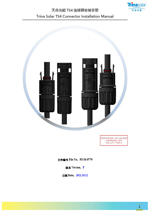
文件编号File No:PS-M-0779 版本Version:F日期Date:2021.10.12目 录 Table ofContent1.安全说明 Safety Instruction ................................................................................................. 4 1.1警告 Warning ................................................................................................................. 4 1.2通用安全 General Safety ............................................................................................... 4 1.3操作安全 Handling Safety .............................................................................................. 5 2.技术参数 Product Specifications .......................................................................................... 7 3.产品选型表 Product Selection Form .................................................................................... 8 3.1 TS4 连接器 TS4 PV connector ....................................................................................... 8 3.2 TS4 Plus 连接器 TS4 Plus PV connector ......................................................................... 8 4.连接器外观尺寸图 Connector Appearance Size Drawing ................................................... 9 4.1 TS4连接器TS4 PV connector . (9)4.1.1正极连接器 Positive Connector.............................................................................. 9 4.1.2负极连接器 Negative Connector .......................................................................... 10 4.2 TS4 Plus 连接器 TS4 Plus PV connector . (11)4.2.1 正极连接器 Positive Connector ........................................................................... 11 4.2.2负极连接器 Negative Connector .......................................................................... 115.安装 Installation .................................................................................................................. 11 5.1工具要求 Tools Requirements ..................................................................................... 11 5.1.1 剥线钳 Wire Stripper ............................................................................................ 11 5.1.2 铆接钳 Rivet Plier .................................................................................................. 12 5.1.3 塑料板手 Plastic Unlocking Spanner .................................................................... 13 5.1.4 工具箱 Tool Box .................................................................................................... 13 5.2组装步骤 Assembly Steps ............................................................................................ 14 5.2.1 剥线 Stripping ....................................................................................................... 14 5.2.2放入插针插套 Inserting pin and socket ............................................................... 14 5.2.3 铆接插针插套 Crimping pin and socket (15)5.2.4插入Pushing (17)5.2.5安装螺帽Install the nut (17)6.连接器对插及解锁Connecting and Disconnecting (19)6.1连接器对插Connecting (19)6.2连接器解锁Disconnecting (19)7.线缆Cable (19)7.1线缆接线Connection of Cable (19)7.2接合状态Connection Status (20)8. 天合光能服务网点Trina Solar Service Point (20)1.安全说明Safety Instruction该产品只能由有相应资质的或经过专家培训的专业人员安装,安装过程中需要遵守所有安全规范。
ipx115d-125d 快速安装指南说明书

1.GENERAL WARNINGSREAD THE GENERAL WARNINGS AND SAFETY PRECAUTIONS CAREFULLY BEFORE INSTALLING AND USING THE DEVICE. • This manual is an integral part of the product and must be kept near the device for quick and easy consultation. • The regulator must not be used for purposes other than those described below, and it especially cannot be used as a safety device.• Before proceeding with installation and use check the limits of application.• Dixell Srl reserves the right to vary the components of its products without prior notice to the customer, ensuring the identical and unchanged features of the same.1.1 SAFETY PRECAUTIONS• Comply with the temperature and humidity limits specified in this document and on the label on the instrument. • Uninstall the device only once you have removed all the electrical connections, otherwise the device might break.• Do not open the device; in case of failure or faulty operation send the instrument back to the dealer/distributor or to “DIXELL S.r.l.” with a detailed description of the fault.• Do not clean the device with corrosive chemical products, solvents or aggressive detergents.•Communication ports (USB, Ethernet) and voltage output are not designed for purposes not specified in this manual that may damage the controller (for example an excessive current request on the USB port to recharge\supply an external device).•The device must not be used in applications that differ from those specified in the following guide. The regulator strictly cannot be installed in the following specific cases:✓ Units installed in systems with lifesaving functions; ✓ Units for military use; ✓ Units operated in nuclear energy systems; ✓ I n all installations where the hardware controller has safety functions1.2 PRODUCT DISPOSAL (WEEE)Complying with the Directive 2012/19/EC of the European Parliament and the Council of July 4 2012, on waste electrical and electronic equipment (WEEE), we inform you that: • There lies the obligation not to dispose of electrical and electronic waste as municipal waste but to separate the waste.• Public or private collection points must be used for disposal, in accordance with local laws. Furthermore, at the end of the equipment life cycle, it is also possible to return it to the dealer when a new purchase is made. • This equipment may contain hazardous substances. Improper use or incorrect disposal can have adverse effects on human health and the environment.• The symbol shown on the product or the package indicates that the product was placed on the market after 13th August 2005 and must be disposed of as separated waste.• Should the product be disposed of incorrectly, sanctions may be applied as stipulated in applicable local regulations regarding waste disposal.2 GENERAL DESCRIPTIONThe iPro family is made of a wide range of devices developed by Dixell: programmable controllers, expansion boards, valve drivers and graphical interfaces. The combination of these devices allows a complete management of any kind of application in various fields, such as air conditioning, industrial refrigeration, residential refrigeration, etc. It is an advanced and flexible solution that can be adapted to any need of the customer or of the final application. Any Dixell product, which is considered a high technology device, requires qualified configuration, programming and commissioning phases to be used in the optimal way possible. Skipping one or more of those phases may cause malfunctioning or damages of the product for which Dixell cannot be held responsible. Do not use the product for uses that differ from those indicated in this documentation. The costumer assumes any responsibility and risk related to the configuration of the product to reach the desired results according to the final installation and use.3 DEVICE GROUNDINGTo guarantee the correct functionalities and health of the controller as well as to avoid malfunctioning and damages to the same, it is mandatory respect the following rules: • Use double insulation transformers for the controller main power supply and never ground the secondary wiring of the transformer.• Verify that the Ethernet cable and that the Switch\Router used to connect it don’t have the shield grounded. •In case of shielded cables used for the communication port connections, it is possible to ground the shield only if it is not used as reference for the communication lines and if it is not physically connected in any way to the controller.•Always check the on the devices connected to the controller (active probes and transducers, loads driven by the analog outputs, devices connected over the communication lines) in order to verify the presence of groundings before powering on the controller. Always verify preventively/in advance the presence of ground meshes in order to remove them before the powering of the plant\electrical board.4CONNECTORSIn the following table a list of the suggested connectors is available (these connectors are available also from Dixell). For every model the maximum configuration set available is shown.Model Connectors QtyIPX115DFemale connector Molex Micro-Fit 5x2 poles 1 Female connector Molex Micro-Fit 8x2 poles 1 Female connector Molex Micro-Fit 11x2 poles 1 Female connector Stelvio CPF 2 poles pin spacing 5,00 90G 1Female connector Stelvio CPF 3 poles pin spacing 5,00 90G 1 Female connector Molex Mini-Fit 2x3 poles 1 Female connector Molex Mini-Fit 2x4 poles 1 Female connector Molex Mini-Fit 2x5 poles 1 IPX125DFemale connector Molex Micro-Fit 5x2 poles 1 Female connector Molex Micro-Fit 8x2 poles 1 Female connector Molex Micro-Fit 11x2 poles 1 Female connector Stelvio CPF 2 poles pin spacing 5,00 90G 1Female connector Stelvio CPF 3 poles pin spacing 5,00 90G 1 Female connector Molex Mini-Fit 2x3 poles 2 Female connector Molex Mini-Fit 2x4 poles 2 Female connector Molex Mini-Fit 2x5 poles 15 ADDRESS SETTINGEvery expansion board must have an own dedicated address in the iPro network. That address is set via the dip-switchpresent on every board and following a binary enumeration like shown in the following table:1 2 3 4 Adr 0: OFF OFF OFF OFF Adr 1: ON OFF OFF OFF Adr 2: OFF ON OFF OFF Adr 3: ON ON OFF OFF Adr 4: OFF OFF ON OFF Adr 5: ON OFF ON OFF Adr 6: OFF ON ON OFF Adr 7: ON ON ON OFF Adr 8: OFF OFF OFF ON Adr 9: ON OFF OFF ON Adr 10: OFF ON OFF ON Adr 11: ON ON OFF ON Adr 12: OFF OFF ON ON Adr 13: ON OFF ON ON Adr 14: OFF ON ON ON Adr 15:ONONONONIf there is a modification to the address a power cycle is needed in order to confirm the modification➢The address 0 is a broadcast address and must never be used. The range of the valid addresses is from 1 to 15.6COMMUNICATIONOn every IPX device are present a CAN-BUS port and a LAN port used for communicating with any iPro device. The communication lines are mutually exclusive, and this mean that if a device is communicating with the CAN-BUS line it will not be possible to use the LAN communication line without repeating the initialization procedure.At power on, the IPX will be in listening mode on both the communication lines waiting the first valid command. Once this command is received on a communication line, that por twill be designed as active while the other will be disabled automatically6.1 CANBUS LINEThe CAN-BUS line is made by a three wires connection. It can be used with all the 10 din models of iPro devices and IPL device. The wiring connection must be a daisy chain.6.2 LAN LINEThe LAN line is made by a two wires connection. It can be used with all the 4 din models of iPro devices, IPG800 device and IPL device. The wiring connection must be a daisy chain.7 DEVICE LABELEvery controller is provided with an identification label. There follows a brief explanation on the information reported on available looking at the label.7.1 IPX LABEL8 LINE TERMINATION (CAN-BUS) When using the CAN-BUS line is mandatory the use of line termination (jumpers that need to be placed at the side of communication connectors) at the start and at the end of the communication line like highlighted in the following scheme:9 POWER LEDEvery IPX module has a green power LED that indicate the state of the power supply. If the power is supplied properly to the device this LED will be light on.10 ALARM LEDEvery IPX module has a red alarm LED that indicate the alarm state. The alarm state can happen in the following cases:•One or more probes are in alarm (wrong configuration or sensor broken) •Communication alarm (the master is not communicating for 10 seconds or more)➢Is not possibly understand which the active alarm is only looking at the expansion board. Is always needed to check the alarms from the master side.11TECHNICAL FEATURESHousing: Self-estinguishing PC Colour:RAL7012 Dimensions: 10 DIN RailMounting device: DIN bar (EN 50022, DIN 43880) Degree of protection: IP10 - Indoor, Open type device Power supply:24Vac +10/-15%, 50/60Hz 20 - 36VdcRated power:20VA (Vac), 15W (Vdc) Rated Impulse Voltage: 500VOvervoltage category:II –IPX115D – IPX125D Comparative Tracking Index (CTI): 300V Type of action: 1 Pollution degree:2Ambient Operating Temperature and Humidity:IPX115D: -10÷50° C / 20÷85%RH IPX125D: -10÷45° C / 20÷85%RH Shipping and storage temperature: -20÷85°C Resistance to heat: V0 (UL94)AC/DC voltage input:IPX115D – IPX125D: 24Vac/Vdc, 50/60Hz, (Class 2 source - SELV) Sensors/digital inputs: Classe 2 - SELV I\O ports:Classe 2– SELV IPX115D – IPX125D output rating RL1, RL2, RL4, RL5, RL6, RL7, RL8, RL9, RL10, RL12, RL13, RL15, RL20, RL21, RL22, RL23, RL24 and RL25 NO contact:Pilot duty2A, 5A inrush 24Vac class 2 source SELVRL3, RL11 and RL14 NO contact: Pilot Duty1.95A, 19.5A inrush 24Vac class 2 source SELV RL3, RL11 and RL14 NC contact: Pilot Duty (6000 cycles) 1.95A, 19.5A inrush 24Vac class 2 source SELV RL16, RL17, RL18, RL19 SSR: Pilot duty1A, 2.5A inrush 24Vac class 2 source SELVRL max commons current: Rating value per number of relays Analogue outputs: Classe 2 Circuit - SELV Cycles of operation: 30KExternal power: Classe 2 Circuit - SELV Purpose of control: Operating control Construction of control: Incorporated controlApprovals: UL 60730-1, UL 60730-2-9CAN/CSA-E60730-1, CAN/CSA-E60730-2-9IPX115D – IPX125DProduct model nameHow To Order. Identification for the product optionsDixell product codeCertifications Technical dataProduction week12INPUT\OUTPUT TECHNICAL DATA 12.1IPX115D – IPX125D➢The SSR relays are sensible to the electromagnetic interferences. These interferences may cause unwanted openings or closings of the contacts. If there is the suspect of this kind of situation, it is recommended to use an external power supply to power the SSR loads. Independently of the above situation, it is highly recomm ended that the track of the signal cables should be separated fromthe track of the power cables➢The SSR outputs are not designed to drive contactors or inductive loads. For any unusual use of the SSR relays contact Dixell for a preventive briefing13DIMENSIONS(Dimensions expressed in mm)14ELECTRICAL CONNECTION 14.1IPX115D14.2IPX125D。
LD5501EN安装使用说明书
目录第一章 概述 (1)第二章 产品特点 (1)第三章 结构特征与工作原理 (2)3.1 结构特征 (2)3.1.1 结构外形 (2)3.1.2 内部结构 (3)3.1.3 面板控制锁说明 (3)3.1.4 每路指示灯和按键说明 (3)3.2 工作原理 (5)第四章 技术特性 (5)第五章 安装与调试 (6)5.1 安装说明 (6)5.1.1 安装尺寸 (6)5.1.2 开箱检查 (6)5.2 外接端子说明 (7)5.2.1 外接设备端子连接说明 (7)5.2.2 现场布线要求 (8)5.2.3 外接设备连接注意事项 (9)5.3 设置说明 (9)5.3.1 地址设置 (10)5.3.2 控制器的相关设置 (10)5.3.2.1 地址类型设置 (10)5.3.2.2 延时设置 (10)5.3.2.3 逻辑设置 (12)5.3.3 故障检测设置 (12)5.4 调试 (14)5.4.1 气体灭火盘系统调试 (14)5.4.1.1查看地址 (14)5.4.1.2自检操作 (14)5.4.1.3复位操作 (14)5.4.2 逻辑启动功能调试 (14)5.4.3 手动启动功能调试 (15)5.4.4 现场紧急启动功能调试 (16)5.4.5 按键保护罩的安装 (16)第六章 使用及操作 (17)6.1 正常监测状态 (17)6.2 启动钢瓶(1谨慎操作) (19)6.2.1 自动启动(延时启动) (19)6.2.2 手动启动(无延时启动,谨慎操作!!!) (19)6.2.3 现场紧急启动(延时启动) (20)6.3 延时中取消启动 (20)6.3.1 停止键操作 (20)6.3.2 现场急停键操作 (21)6.4 复位 (21)6.5 自检 (22)第七章 故障分析与排除方法 (22)第八章 注意事项 (24)第九章 保养与维修 (25)第十章 运输及贮存 (25)第十一章 售后服务 (26)附录1:工程接线示例图 (26)附录2:按键保护罩安装更换方法 (27)第一章 概 述LD5501EN气体灭火控制盘(以下简称气体灭火盘)是依据GA61-2002标准,根据消防规范和消防验收规范研制的,配合我公司生产的LD128EN/LD128E系列火灾报警控制器使用,可根据采集的现场火警信息,智能控制气体灭火系统的执行机构,从而达到准确无误的控制灭火气体喷洒的目的。
GW11A-550安装使用说明书

GW11A-550安装使用说明书1 页1 概述GW11A-550型双柱水平伸缩式户外交流高压隔离开关(以下简称隔离开关)是三相交流50Hz户外高压电器,供高压线路在有电压无负载时分、合线路,以及对被检修的高压母线、断路器等实现安全的电气隔离。
隔离开关在分闸后形成水平方向的绝缘单断口,两侧均可配装接地开关。
接地开关与隔离开关各配有独立的操作机构,但两者间具有机械联锁或电气联锁装臵,确保隔离开关和接地开关两者间操作顺序(主合—地分;地合—主分)正确。
接地开关为单杆分步动作式。
隔离开关具有通流能力大,占地面积小,且机构紧凑,运动装臵密封于导电管内,检修周期长等特点。
2 产品使用环境条件 2.1 海拔高度:不超过2000m。
2.2 环境温度:-40℃至+40℃。
2.3 风压不超过700Pa(相当于风速34m/s)。
2.4 地震烈度不超过8度。
2.5 覆冰厚度不超过20 mm。
2.6 相对湿度:日平均不超过95%;月平均不超过90% 2.7 阳光辐射:不大于1000W/m? 。
2.8 不适于有易燃物质、爆炸危险、化学腐蚀及剧烈震动的场所。
2.9 适用于水平安装场所。
3 产品特征及额定参数 3.1 产品特征:见表1。
表1 特征结构形式a)不接地b)动侧单接地有无接地开关c)静侧单接地d)双接地操作方式单相电动操作,三相电气联动操动机构 3.2 额定参数见表2。
CJ6A会输签入标记处数更改文件号签字日期安装使用说明书编制校核0KA.805.106会签标准化审定批准GW11A-550 双柱水平伸缩式户外高压交流隔离开关安装使用说明书0KA.412.521共18 页第 2 页表2序号 1 2 3 4 5 6 7 8 9 10 11 12 13 项目额定电压,kV 额定电流, A 额定短时耐受电流(有效值),kA 额定短路持续时间,s 额定峰值耐受电流(峰值),kA 对地额定短时工频耐受电压(有效值),kV 断口对地额定雷电冲击耐受电压(峰值),kV 断口对地额定操作冲击耐受电压(峰值),kV 断口额定开断电容电流,A 额定开断电感电流,A 额定频率,Hz 无线电干扰水平单极重量,kg 参数550 3150,4000 63 3 160 740 740(+315)1675 1675(+450)1300 1175(+450)2 0.7 50 在1.1倍额定相电压下①晴天、夜晚无可见电晕;②无线电干扰电压不大于500μV 不地1590、单地1790、双地1990 额定注:1、隔离开关所配用的接地开关额定短时耐受电流和额定峰值耐受电流同主闸刀。
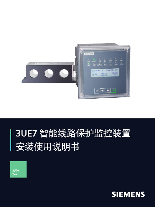
3UE7 智能线路保护监控装置安装使用说明书
智能线路保护监控装置申明版权所有,未经本公司之书面许可,此手册中任何段落,章节内容均不得被摘抄、拷贝或以任何其它形式复制、传播,否则一切后果由违者自负。
本公司保留一切法律权利。
本公司保留对本手册所描述之产品规格进行修改的权利,恕不另行通知。
订货前,请垂询当地代理商以获悉本产品的最新规格。
2目录1 概述 (4)2 产品特点 (5)3 型号说明 (6)4 主要技术指标 (7)5 功能配置 (8)6 安装与接线 (9)6.1 安装说明 (9)6.2 控制器模块外形及安装尺寸 (9)6.3 3UE7系列1A/5A专用电流互感器外形尺寸 (10)6.4 100A及以下电流互感器模块外形尺寸 (11)6.5 160A电流互感器外形尺寸 (12)6.6 400A电流互感器外形尺寸 (13)6.7 漏电流互感器外形尺寸 (14)6.8 端子排列 (15)6.9 端子编号 (16)6.10 产品组成 (17)7 操作指南 (20)7.1 显示操作说明 (20)7.2 3UE7菜单概述 (21)7.3 3UE7各菜单详细描述 (26)7.4 3UE7保护功能介绍 (30)8 通讯 (33)8.1 MODBUS RTU通信协议概述 (33)8.2 3UE7系列通讯地址表 (34)9 典型应用原理图 (44)9.1 3UE7装置接线图 (44)10 订货号 (45)33UE7 系列智能型低压线路保护器适用于额定电压至AC 690V、额定电流至AC 400A、额定频率为50/60Hz的低压系统。
产品体积小,结构紧凑,安装方便,是低压馈线终端的保护、监测和控制的智能化综合装置。
3UE7 系列产品集保护、测量、控制、总线通讯为一体,同时提供了远程自动控制、现场直接控制、面板指示、信号报警、操作记录、跳闸报警记录及开关量记录等功能。
安全性信息Siemens 为其产品及解决方案提供了工业信息安全功能,以支持工厂、系统、机器和网络的安全运行。
XGN80-40.5安装使用说明书
1.2 标准及规范
开关柜满足以下标准:
* GB 1984
高压交流断路器
* GB 3906
3.6~40.5kV 交流金属封闭开关设备和控制设备
* GB/T 11022 高压开关设备通用技术条件
* DL/T 791
户内交流充气式开关柜选用导则
* IEC 62271-1 高压开关设备和控制设备-第 1 部分:共用技术要求
器气室和母线气室)、带操动机构的插入式断路器。
开关柜的气室外壳采用 3mm 不锈钢板,通过三维激 光 焊 机 焊 接 成 相 互 独 立 的 密 封
气室,气箱内面焊有加强筋,保证在高海拔地区气箱的变形在允许范围内。静态密封采用
三元乙丙 O 型圈,动态密封采用波纹管和磁流体,通过以上措施来保证气箱极低的漏气率。
3.2 开关柜绝缘气体系统
高压带电部件安装于充气的封闭气室内,完全不受外界大气条件的影响。 * 每台开关柜的断路器气室及母线气室均为独立气室,均有独立的气体系统。柜间气室
也相互独立。 * 气室内配袋装干燥剂。
运行压力检测: * 开关柜每个独立气室的额定充气压力由独立的密度控制器(图 3-2)进行监测。 --断路器气室的密度控制器 --母线气室的密度控制器 * 密度控制器,具有环境温度补偿功能。 * 气体额定工作压力为 0.05MPa(相对压力),当低于 0.03MPa(相对压力)时,智能控
1.3 运行条件
* 环境温度不高于+40℃,不低于-25℃; * 相对湿度:日平均值不大于 95%,月平均值不大于 90%; * 海拔高度不大于 5000m; * 地震烈度不超过 8 度; * 无火灾爆炸、严重污秽、化学腐蚀及剧烈震动的场所; 注:特殊环境条件请咨询制造商。
- 1、下载文档前请自行甄别文档内容的完整性,平台不提供额外的编辑、内容补充、找答案等附加服务。
- 2、"仅部分预览"的文档,不可在线预览部分如存在完整性等问题,可反馈申请退款(可完整预览的文档不适用该条件!)。
- 3、如文档侵犯您的权益,请联系客服反馈,我们会尽快为您处理(人工客服工作时间:9:00-18:30)。
安装说明书
一、程序:
施工准备→放线→挖基槽排地下水→探钎(最少不低于三个点)→基层找平、夯实→铺
砂→吊装→调整使用产品平衡→罐体开孔接管→分层回填→灌水→夯实回填→砌检查井→
顶部回填层夯实→地面处理
二、工艺:
第一步:挖坑槽
1. 根据采用化粪池的型号,测量厂家放线,在确定能保证产品尺寸的情况下进行挖槽。
2. 根据型号的大小,必须进行放坡,放坡大小根据土质情况及产品顶部以上的复土厚度。
3. 挖槽前应准备好电源、水泵、铁锨、盒尺、测量仪器等,施工中必备的工具,以备出现
特殊情况使用。
4. 所挖出的土,必须距槽四周5米以外,防止土的侧压造成塌方,另外也给吊装产品时留
有工作场地。
5. 遇有地下水时应首先对地下水进行排除,根据示意图尺寸及要求进行基础处理,后进行
铺砂。
6. 无地下水时,对基础进行夯实、铺砂。根据示意图及要求进行基础处理。
7. 根据示意图,在回填时底部必须铺砂,两塞尽量采用砂填水夯,如确定无砂两塞可采用
土填,但填时必须使用专职工具进行砸实。
8. 二次坑槽以上回填土执行回填规范进行回填,绝对不能用建筑垃圾代替回填土。
9. 可根据实际情况,采用组合式安装。
第二步:安装
1、 对基槽底进行探钎。根据产品型号的长度最低不应少于三点,深度600-800mm。
2、 基层夯实。
3、 铺砂100mm并找平,砂内不允许有尖角、石块等杂物。
4、 吊装就位。在吊装就位时,必须注意化粪池的进出水口方向。
5、 产品吊装就位后,要测定水平度,如不平应进行调整,使之水平。
6、 分层回填土:
① 回填土之前必须将池内灌水1/2.,目的在回填时使产品内外受压平衡。
② 回填土是安装化粪池最主要的环节,回填土的密实程度直接影响此产品的使用,以
及下道工序的作法。
③ 在回填土时,产品底部两侧必须用人工塞实,随填随塞实。填到30-50cm以上时,
每30cm必须夯实一次。回填到产品1/2后,往产品内继续灌水,距产品顶部40-50cm
后再进行回填土。每30cm进行夯实,直至与产品顶部相平。
④ 产品顶部以上回填土必须密实,如产品设在道路地段,在地面未处理之前,绝对不
允许有车辆进行碾轧。
⑤ 回填时回填土的质量必须符合回填土验收规范,绝对不允许用建筑垃圾作为回填土
使用。土中的尖角、石块及硬杂物必须剔出,回填时,必须均匀回填,切忌局部猛力
冲击。
第三步:砌检查井
砌检查井可在产品顶部回填土之前进行,也可在顶部回填之后进行,根据施工现场而
定。
三、下水情况下的设备安装:
水位较高的地区,可采用明降水挖槽。采用明降水挖槽时,必须做好施工前的准备工作。
具体作法如下:
1、 坑槽挖好后,如遇坑槽内有泥浆,应再挖深20-33cm。将深坑槽内的水抽净后铺设干性
混凝土,使之找平,目的是使产品安装后沉降一致。
2、 回填土前,产品内灌水1/2,使之再进行回填。绝对不允许回填污泥,以防产品上浮,
回填土执行无水回填土要求。