微型压力传感器
最新MEMS压力传感器的结构与工作原理及应用技术

M E M S压力传感器的结构与工作原理及应用技术MEMS压力传感器的结构与工作原理及应用技术MEMS是指集微型压力传感器、执行器以及信号处理和控制电路、接口电路、通信和电源于一体的微型机电系统。
MEMS压力传感器可以用类似集成电路(IC)设计技术和制造工艺,进行高精度、低成本的大批量生产,从而为消费电子和工业过程控制产品用低廉的成本大量使用MEMS传感器打开方便之门,使压力控制变得简单易用和智能化。
MEMS压力传感器原理:目前的MEMS压力传感器有硅压阻式压力传感器和硅电容式压力传感器,两者都是在硅片上生成的微机械电子传感器。
硅压阻式压力传感器是采用高精密半导体电阻应变片组成惠斯顿电桥作为力电变换测量电路的,具有较高的测量精度、较低的功耗,极低的成本。
惠斯顿电桥的压阻式传感器,如无压力变化,其输出为零,几乎不耗电。
MEMS硅压阻式压力传感器采用周边固定的圆形的应力杯硅薄膜内壁,采用MEMS技术直接将四个高精密半导体应变片刻制在其表面应力最大处,组成惠斯顿测量电桥,作为力电变换测量电路,将压力这个物理量直接变换成电量,其测量精度能达0.01%~0.03%FS。
硅压阻式压力传感器结构如图3所示,上下二层是玻璃体,中间是硅片,硅片中部做成一应力杯,其应力硅薄膜上部有一真空腔,使之成为一个典型的绝压压力传感器。
应力硅薄膜与真空腔接触这一面经光刻生成如图2的电阻应变片电桥电路。
当外面的压力经引压腔进入传感器应力杯中,应力硅薄膜会因受外力作用而微微向上鼓起,发生弹性变形,四个电阻应变片因此而发生电阻变化,破坏原先的惠斯顿电桥电路平衡,电桥输出与压力成正比的电压信号。
传统的机械量压力传感器是基于金属弹性体受力变形,由机械量弹性变形到电量转换输出,因此它不可能如MEMS压力传感器那样做得像IC那么微小,成本也远远高于MEMS压力传感器。
相对于传统的机械量传感器,MEMS压力传感器的尺寸更小,最大的不超过1cm,使性价比相对于传统“机械”制造技术大幅度提高。
微型压力传感器的参数
微型压力传感器的参数微型压力传感器是一种广泛应用于工业、航空、汽车、医疗、生活等领域的高性能、高精度的压力测量设备。
在应用中,合理选择和掌握传感器的参数是非常重要的,下面我们将介绍微型压力传感器的主要参数。
1.测量范围测量范围是指传感器可测量的压力范围,一般用最小测量值和最大测量值来表示。
微型压力传感器的测量范围有限制,通常其可以承受的最大压力为3至5倍的额定测量压力。
2.精度精度是指传感器输出值与被测压力的实际值之间的偏差,它是微型压力传感器重要的参数。
传感器的精度一般用百分比表示,它与该传感器的测量范围有关。
在实际应用中,选择合适的精度可以有效地提高测量结果的准确度。
3.温度影响温度对微型压力传感器的测量结果具有较大的影响,因此温度稳定性是非常重要的参数。
温度影响是指在不同的温度下传感器的精度是否有变化,一般用百分比表示。
通常,传感器的精度将随着温度变化而变化,因此在选购之前应注意传感器的温度特性。
4.响应时间响应时间是指传感器在受到外界压力作用后,输出信号达到稳定状态所需要的时间。
响应时间通常受到传感器结构和体积的制约。
一般情况下,响应时间越短,传感器的性能越好。
5.零漂零漂是指传感器在无外界压力作用时输出的信号是否为零。
在实际应用中,传感器输出的信号可能会因为机械、设备或传感器本身的原因而受到外界干扰。
因此,应选择零漂小的传感器,以确保测量结果的准确性。
6.重复性重复性是指传感器在相同压力下测量多次所得结果间的一致性。
在实际应用中,由于传感器受到多种因素的影响,可能会导致测量结果间出现波动。
因此,在选购时应注意传感器的重复性。
综上所述,微型压力传感器的参数包括测量范围、精度、温度影响、响应时间、零漂和重复性,这些参数对于传感器的效果及应用效果都具有非常重要的影响。
在实际应用中,应根据具体的实际情况,选择合适的传感器并合理应用。
意法推出新款微型压力传感器
凌力 尔特公 司推 出一款精 准 RF .功率检波器
凌 力 尔 特 公 司 日前 推 出 一 款 精 准 R F功 率 检 波 器 L C 54 T 56 。该器件在 6 0 z 1G z 0 MH 至 5 H 的频率范围内工作 , 对 脉冲R F信号具有 出色 的 7 s n 快速响应时间 。此外 , 该器件还 具 有一个传 播延迟为 9 s 内置快速 比较 器。该 比较器的 门 n的
F A综合 F A和 V P) P A面板 , 即面板一侧为类似 V A的垂直配向 膜, 另一侧则是倾斜的 F A配向膜 。 P 新技 术实现了更高 的响应
速 度 和 对 比度 , 其 是 在 低 电 压 情 况 下 的 响 应 速 度 大 大 提 升 。 尤
除了实现 3 s以下的响应时问 , 足 3 m 满 D显示和高帧速视频显
5 . 5英寸与 1.英寸两种版本。 中,. 08 其 5 5英寸版本屏幕分辨率 为 12 0 素 ,而 1. 04 6 像 x0 08英寸版本 的屏幕分辨率更是高达 16 3 6×80像素 。此外 ,夏 普 G l ao 还 具 备 一 以及 0 aa gs p H mcoD储存卡扩展等功能。 i S r
潜力将会 进一 步增 大,而众 多电子厂商也在纷纷推 出其平板
电脑产品, 更是让平板 电脑市场的热度持续上升。而作 为知名 的 日系手机厂商 , 夏普公司近 日正式公布 了其 全新 A do n ri d系
统 平 板 电 脑— — 夏 普 G l ao。该 G l ao 平 板 电脑 分 为 a pgs a a p gs a
号测 量的性 能扩展至 1 位 , 2 电压测量 范围可 达微伏 级 , 能够 用 于多种 类 型的传 感器 , 例如 : 向异性磁 阻 (M ) 各 A R 传感 器 。 A MR传感器在汽车或工业系统 中通常用于线位移 或角位移的
OMEGA LCKD系列微型压力传感器指南说明书

e-mail:**************For latest product manuals:User’s GuideLCKD SERIESSubminiature CompressionLoad CellsShop online at1Each LCKD Series Load Cell incorporates a small printed circuit board into the load cell’s lead wire. DO NOT remove this board or cut the cable between the compensation board and load cell. Removal of this board voids the calibration and warranty of the load cell.GeneralThe OMEGA®LCKD Series subminiature compression load cells arecompression-only units that are highly cost-effective. To ensureexcellent long-term stability and reliability in severe environments, theLCKD Series utilize high quality strain gages, precision gagingtechniques and all stainless steel construction. These units have a loadbutton machined as an integral part of the basic load cell. The load cellis designed to operate by mounting on a flat surface. The LCKD mustrest on a flat surface the same diameter as the D1dimension for properoperation.Shunt CalibrationThe LCKD Series are highly accurate millivolt output type load cellswith shunt calibrator for quick calibration checks. Shunt calibrationallows the user to install and calibrate the instrument in the fieldwithout the use of a dead weight tester. A 59 kilohm resistor is shortedacross negative excitation and negative signal output at the factory,which produces a simulated millivolt signal out of the transducer. Theshunt calibration signal is equivalent to a simulated pressure of:Shunt Cal mV/VSimulated Load = x Full Scale LoadCalibration Factor mV/VExample: Model LCKDWhere:Calibration Factor - 2.0315 mV/VShunt Cal - 1.4962 mV/VSimulated Load = 1.4962x 50 = 36.852.0315To set up the transducer in the field, follow these steps:1. Connect transducer excitation terminals to dc power supply.2. Connect transducer signal output terminals to readout instrument(DVM, Analog meter, etc.)3. Turn power on.4. Null transducer signal output with zero adjust potentiometer on meter.5. Short a 59 kilohm resistor across negative excitation and negativesignal output.6. Adjust the span potentiometer until the readout instrument reads thesimulated load as computed above (or that percent of full scalepressure).7. Remove 59 kilohm resistor and repeat steps 4 to 6 if necessary.(Span and Zero adjust pots may interact).8. The meter is now calibrated.IMPORTANT:Every load cell comes with a calibration sheet stating its full scale output, and this manual. Please save both.Specifications:Signal Output:See calibration sheetLinearity and Hysteresis:±0.25% full scaleRepeatability:±0.1% full scaleCompensated Temperature Range:60 to 160°F (16 to 71°C)Operating Temperature Range:-65°to 225°F (-54 to 107°C)Temperature Effect:Zero 0.01% full scale/°F;Span 0.01% of reading/°F Bridge Resistance:350 ohm bonded foil gageExcitation Voltage: 5 Vdc, 7 Vdc max.Full Scale Deflection:0.001" to 0.003"Safe Overload:150%Construction:Stainless SteelElectrical: 5 ft. four conductor cableWeight:<0.5 oz.WIRING CODERED(+) EXCITATIONBLACK(–) EXCITATIONGREEN(–) OUTPUTWHITE (+) OUTPUT2M4087-0305It is the policy of OMEGA Engineering, Inc. to comply with all worldwide safety and EMC/EMI regulations that apply. OMEGA is constantly pursuing certification of its products to the European New Approach Directives. OMEGA will add the CE mark to every appropriate device upon certification.The information contained in this document is believed to be correct, but OMEGA accepts no liability for any errors it contains, and reserves the right to alter specifications without notice.WARNING: These products are not designed for use in, and should not be used for, human applications.Direct all warranty and repair requests/inquiries to the OMEGA Customer Service Department. BEFORE RET URNING ANY PRODUCT (S) T O OMEGA, PURCHASER MUST OBT AIN AN AUT HORIZED RET URN (AR) NUMBER FROM OMEGA’S CUST OMER SERVICE DEPART MENT (IN ORDER T O AVOID PROCESSING DELAYS). T he assigned AR number should then be marked on the outside of the return package and on any correspondence.The purchaser is responsible for shipping charges, freight, insurance and proper packaging to prevent breakage in transit. FOR WARRANTY RETURNS, please have the following informa-tion available BEFORE contacting OMEGA:1.Purchase Order number under which the product was PURCHASED,2.Model and serial number of the product under warranty, and3.Repair instructions and/or specific problems relative to the product.FOR NON-WARRANTY REPAIRS,consult OMEGA for cur-rent repair charges. Have the following information avail-able BEFORE contacting OMEGA:1. Purchase Order number to cover the COST of the repair,2.Model and serial number of the product, and3.Repair instructions and/or specific problems relative to the product.OMEGA’s policy is to make running changes, not model changes, whenever an improvement is possible. This affords our customers the latest in technology and engineering.OMEGA is a registered trademark of OMEGA ENGINEERING, INC.© Copyright 2005 OMEGA ENGINEERING, INC. All rights reserved. T his document may not be copied, photocopied, reproduced, translated, or reduced to any electronic medium or machine-readable form, in whole or in part, without the prior written consent of OMEGA ENGINEERING, INC.Servicing North America:U.S.A.:One Omega Drive, Box 4047ISO 9001 Certified Stamford, CT 06907-0047Tel: (203) 359-1660FAX: (203) 359-7700e-mail:**************Canada:976 BergarLaval (Quebec) H7L 5A1, Canada Tel: (514) 856-6928FAX: (514) 856-6886e-mail:*************For immediate technical or application assistance:U.S.A. andSales Service: 1-800-826-6342 / 1-800-TC-OMEGA Canada:Customer Service: 1-800-622-2378 / 1-800-622-BEST Engineering Service: 1-800-872-9436 / 1-800-USA-WHEN Mexico:En Espan ˜ol: (001) 203-359-7803e-mail:*****************FAX: (001) 203-359-7807**************.mxServicing Europe:Benelux:Postbus 8034, 1180 LA Amstelveen, The Netherlands Tel: +31 (0)20 3472121FAX: +31 (0)20 6434643Toll Free in Benelux: 0800 0993344e-mail:*****************Czech Frystatska 184, 733 01 Karviná, Czech Republic Republic:Tel: +420 (0)59 6311899FAX: +420 (0)59 6311114Toll Free: 0800-1-66342e-mail:*****************France:11, rue Jacques Cartier, 78280 Guyancourt, France Tel: +33 (0)1 61 37 2900FAX: +33 (0)1 30 57 5427Toll Free in France: 0800 466 342e-mail:**************Germany/Daimlerstrasse 26, D-75392 Deckenpfronn, Germany Austria:Tel: +49 (0)7056 9398-0FAX: +49 (0)7056 9398-29TollFreeinGermany************e-mail:*************United One Omega Drive, River Bend Technology Centre Kingdom:Northbank, Irlam, ManchesterISO 9002 Certified M44 5BD United KingdomTel: +44 (0)161 777 6611FAX: +44 (0)161 777 6622Toll Free in United Kingdom: 0800-488-488e-mail:**************.uk。
LH-S09A 微型拉压力传感器特点及用途,LH-S09A 微型拉压力传感器技术参数
LH-S09A 微型拉压力传感器特点及用途,LH-S09A 微型拉压力传感器技术参数随着中国自动化不断发展进步,工控自动化产品也是大众需求。
上海力恒传感技术有限公司致力于力传感器及其信号处理的系统工作,公司在力传感器领域有着不断的追求。
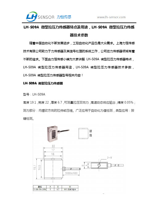
下面由力恒传感小编为大家讲解LH-S09A 微型拉压力传感器特点,LH-S09A 微型拉压力传感器用途,LH-S09A 微型拉压力传感器技术参数,LH-S09A 微型拉压力传感器型号相关内容!LH-S09A 微型拉压力传感器型号:LH-S09A高度19.1,宽度22,厚度6.7,可测量拉压双向力;高速动态响应输出,精度0.05%;测力部分:内螺纹方向的拉伸或压缩。
广泛应用于自动化力值检测,典型应用:按键检测。
注:1、螺丝安装时,深度不可超过4毫米。
不可接触到传感器中间部分,以免影响测量结果。
2、传感器安装时,两边盖板不可与中间柱体接触,否则影响测试准度。
注:螺丝安装时,不能拧太深。
不可接触到传感器中间部分,以免影响测量结果。
技术参数量程Capacity 0-1N~50N~2000N材质Material不锈钢输出灵敏度Rated output 2.0 ±10% mV/V输出电阻Output Impedance350±3Ω非线性Non-linearity 0.05 % F.S.绝缘电阻Insulation>5000MΩ/10VDC滞后Hysteresis 0.05 % F.S.使用电压Recommended2.5-5V以上内容是由上海力恒传感技术有限公司小编整理,希望能帮助到大家~ 上海力恒传感技术有限公司致力于力传感器及其信号处理的系统工作,公司在力传感器领域有着不断的追求。
Excitation重复性 Repeatability0.05 % F.S. 至大工作电压 Excitation max 10V蠕变(30分钟) Creep(30min)0.05 % F.S.温度补偿范围Compensated Temp Range -10~60℃温度灵敏度漂移 Temp Effect OnOutput 0.1 % F.S./ 10℃工作温度范围Operating TempRange-20~80℃ 零点温度漂移 Temp Effect OnZero0.1 % F.S./ 10℃安全负载 Safe Load120%防护等级 Protection ClassIP 65极限负载Ultimate LoadLimit 150%输入阻抗 Input Impedance350±15Ω电缆长度Cable Length∅2-3 x 3m电缆线连接方式 Wire Connection Ex +: 红 (Red) ; Ex -: 黑 (Black) ; Sig +: 绿 (Green ); Sig -: 白 (White)(压为正,拉为负);随着中国自动化不断发展进步,我们团队积累了多年一线工作经验。
MEMS传感器原理

微型传感器的历史
早在60年代初,就已开发出了实用半导 体应变片;MEMS First Bucket of Gold
1962年第一个硅微型压力传感器问世 ; 79年研制出第一个微硅加速度计; 94年出现了大批量生产的用于汽车防撞
∆ρ =πσ = πEε = πE ∆L
ρ
L
其中:
π——材料的压阻系数 E——弹性模量 ε——应变
一般金属材料的压阻系数很小,可以忽略。而半导体材
料的压阻系数π却很大 。对于硅半导体材料,材料的灵敏 度系数(Gauge Factor) G = ∆R ≈ πE 一般在70~170之间 。
εR
硅膜上的电阻在应力作用下相对变化为:
传感器 量程:1Psi~
250Psi (1Psi ≈ 6.9KPa)
压阻式微型压力传 感器的特点
优点:制作工艺、检测电路简单, 得到最广泛的应用。
缺点: 温度漂移大,需温度补偿。
1. 2 电容式微型压力传感器 Capacitive Pressure Sensor
电容式传感器将被测量转换成电容量变化,一般 敏感元件为可变电容器的形式。
微型压力传感器有各种工作原理, 如:压阻、电容、场发射和光纤等。
1.1 压阻式微型压力传感器
Piezoresistive Pressure Sensor
压阻式压力传感器基本原理:将作用于薄膜的被测压力, 通过薄膜的应力转换成电阻值的变化,再经相应的测量电 路测出被测量值。
压阻式微型压力传感器利用半导体材料的压阻效应,即材 料受到应力作用时,其电阻或电阻率发生变化。
微型压力传感器校准方法

微型压力传感器校准方法
1.准备校准设备:压力计、校准器、液压泵。
2.将微型压力传感器接入校准器,通过液压泵向其输入预设初始压力(以高精度压力计读取即可),此时应确保高精度压力计和微型压力传感器共用一个底座。
3.根据微型压力传感器的初始读数进行修正和校准,以获得准确的读数。
4.根据调整结果,将液压泵调节到设定的压力,继续观察微型压力传感器的结果,再次进行校准,直到压力传感器读数最终稳定。
5.将微型压力传感器更换后,重新进行以上步骤,完成所有传感器的校准。
微型压力传感器的使用方法

微型压力传感器的使用方法微型压力传感器是一种可以测量物体表面压力的精密仪器。
它通常由传感器和读数仪两部分组成。
首先,将微型压力传感器放置在需要测量压力的物体表面上。
确保传感器完全接触物体表面,然后将读数仪连接到传感器上。
接下来,打开读数仪并选择所需的测量单位和范围。
对于大多数微型压力传感器,可以选择psi、kPa、bar等测量单位。
开始进行测量前,请确保物体表面没有任何杂质,以免影响测量结果。
然后,轻轻地施加压力在传感器上,使其读数仪显示压力值。
测量完成后,注意将传感器从物体表面上取下。
最后,将读数仪归零并储存数据,以备未来参考。
总的来说,微型压力传感器是一种广泛应用于工业控制、科学研究、医学等领域的重要工具,正确的使用方法可以保证测量结果的准确性和可靠性。
- 1、下载文档前请自行甄别文档内容的完整性,平台不提供额外的编辑、内容补充、找答案等附加服务。
- 2、"仅部分预览"的文档,不可在线预览部分如存在完整性等问题,可反馈申请退款(可完整预览的文档不适用该条件!)。
- 3、如文档侵犯您的权益,请联系客服反馈,我们会尽快为您处理(人工客服工作时间:9:00-18:30)。
Capacity/ 35101520305075100kg////////Rated Output0.9~1.5mV/V Compensated Temp.-10...+60°CExcitation3~10V Operating Temp.-20...+80°CZero Balance±5% of R.O.Temp. Shift Zero±0.01% of R.O./°CNonlinearity±0.5% of R.O.Temp. Shift Span±0.01% of R.O./°CHysteresis±0.5% of R.O.Input Resistance350±10ΩNonrepeatability±0.2% of R.O.Output Resistance350±3ΩCreep(30min)±0.1% of R.O.Insulation Resistance>5000MΩ(50V)Safe Overload150% of F.S.Ingress ProtectionIP65Ultimate Overload200% of F.S.Material of ElementStainless steelCableØ21000mm 4-core shielded cable*Ø2*1000mm 4R.O.=Rated Output F.S.=Full Scale/ /------Specifications/Wiring Diagram/Input(+):RedOutput(-):WhiteInput(-):BlackOutput(+):GreenShield(+):(-):(-):(+):Load directionCapacity/ 2510kg//Rated Output0.8~1.8mV/V Compensated Temp.-10...+40°CExcitation3~10V Operating Temp.-20...+60°CZero Balance±3% of R.O.Temp. Shift Zero±0.01% of R.O./°CNonlinearity±0.5% of R.O.Temp. Shift Span±0.01% of R.O./°CHysteresis±0.5% of R.O.Input Resistance350±50ΩNonrepeatability±0.2% of R.O.Output Resistance350±5ΩCreep(30min)±0.2% of R.O.Insulation Resistance>5000MΩ(50V)Safe Overload120% of F.S.Ingress ProtectionIP65Ultimate Overload150% of F.S.Material of ElementStainless steelCableØ21000mm 4-core shielded cable*Ø2*1000mm 4R.O.=Rated Output F.S.=Full Scale//------Specifications/Wiring Diagram/Input(+):RedOutput(-):WhiteInput(-):BlackOutput(+):GreenShield(+):(-):(-):(+):Load directionWiring Diagram /Input(+):Red Output(-):White Input(-):Black Output(+):Green Shield(+): (-): (-): (+):Capacity /35101520305075100150200kg//////////Rated Output 0.8~1.8mV/VCompensated Temp. -10...+60°C Excitation 3~10V Operating Temp. -20...+80°C Zero Balance ±5% of R.O.Temp. Shift Zero ±0.01% of R.O./°C Nonlinearity ±0.5% of R.O .Temp. Shift Span ±0.01% of R.O./°CHysteresis ±0.5% of R.O.Input Resistance350±30ΩNonrepeatability±0.2% of R.O.Output Resistance350±5ΩCreep(30min)±0.2% of R.O.Insulation Resistance>5000MΩ(50V)Safe Overload 150% of F.S.Ingress ProtectionIP65Ultimate Overload200% of F.S.Material of ElementStainless steelCableØ21000mm 4-core shielded cable*Ø2*1000mm 4R.O.=Rated Output F.S.=Full Scale //------Specifications /Capacity/(kg)A3~20 1.530~2003250~3004Capacity /3510203050100150200250300kg//////////Rated Output 0.9~1.8mV/VCompensated Temp. -10...+60°C Excitation 3~10V Operating Temp. -20...+80°C Zero Balance ±3% of R.O.Temp. Shift Zero ±0.01% of R.O./°C Nonlinearity ±0.5% of R.O .Temp. Shift Span ±0.01% of R.O./°CHysteresis ±0.5% of R.O.Input Resistance350±10ΩNonrepeatability±0.2% of R.O.Output Resistance350±3ΩCreep(30min)±0.2% of R.O.Insulation Resistance>5000MΩ(50V)Safe Overload 150% of F.S.Ingress ProtectionIP65Ultimate Overload200% of F.S.Material of ElementStainless steelCableØ31000mm 4-core shielded cable*Ø3*1000mm 4R.O.=Rated Output F.S.=Full Scale //------Specifications / Wiring Diagram /Input(+):RedOutput(-):White Input(-):Black Output(+):GreenShield(+): (-): (-): (+):Load directionCapacity /510203050751001502003005007501000kg////////////Rated Output 0.9~2.0mV/VCompensated Temp. -10...+60°C Excitation 3~12V Operating Temp. -20...+80°C Zero Balance ±3% of R.O.Temp. Shift Zero ±0.01% of R.O./°C Nonlinearity ±0.3% of R.O .Temp. Shift Span ±0.01% of R.O./°CHysteresis ±0.3% of R.O.Input Resistance350±10ΩNonrepeatability±0.1% of R.O.Output Resistance350±3ΩCreep(30min)±0.1% of R.O.Insulation Resistance>5000MΩ(50V)Safe Overload 150% of F.S.Ingress ProtectionIP65Ultimate Overload200% of F.S.Material of ElementStainless steelCableØ31000mm 4-core shielded cable*Ø3*1000mm 4R.O.=Rated Output F.S.=Full Scale //------Specifications / Wiring Diagram/Input(+):Red Output(-):White Input(-):Black Output(+):Green Shield(+): (-): (-): (+):。