ANSYS—APDL语言参数提取总结
ANSYS—APDL语言参数提取总结
APDL语言之提取参数常用命令1.1常用提取信息之APDL语句*GET, Par, Entity, ENTNUM, Item1, IT1NUM, Item2, IT2NUM !获取一些参数信息*Get,nnod,NODE,0,COUNT !得到节点数*Get,nele,ELEM,0,COUNT !得到单元数*Get,nnod,NODE,2,D,VOLT !得到节点的载荷约束*VGET, ParR, Entity, ENTNUM, Item1, IT1NUM, Item2, IT2NUM, KLOOP !作用与*get指令相似,多一个loop参数,表示循环*VGET,nodx(1),NODE,1,loc,X, , ,2 !获得节点X坐标*DIM, Par, Type, IMAX, JMAX, KMAX, Var1, Var2, Var3, CSYSID !定义矩阵变量及维数*Dim,nodx,array,nnod !定义节点X坐标数组维数LSEL, Type, Item, Comp, VMIN, VMAX, VINC, KSWP !选择线上的子单元(节点,关键点等) !与此命令相关的还有选择面上单元等相关选择指令lsel,s,,,1,2,,1 !选择线1和线2上的所有信息(节点等)allsel,all !选择所有DNSOL, NODE, Item, Comp, V1, V2, V3, V4, V5, V6 !定义或者修改节点上的计算结果DNSOL, 1,VOLT, , 0.000000 !定义节点1的电位为0V*USE, Name, ARG1, ARG2, ARG3, ARG4, ARG5, ARG6, ARG7, ARG8, ARG9, AR10, AR11, AR12, AR13, AR14, AG15, AR16, AR17, AR18 !执行宏文件*use,bondcondition.txt !执行bondcondition.txt文件中的宏指令,无输入参数1.2常用提取数据语句提取一个模型的数据主要包括三个方面:(1)离散网格各个节点的坐标值;(2)各个单元的节点组成及单元的材料属性;(3)边界条件的要求,即提取边界线上及面上的节点编号及结点上的载荷束缚。
基于ANSYS参数化语言APDL的结构优化设计

u Y N 设计 变量 ) 始化 , 构建 初 并 A Y NS S提供的参数化设计语 言( P )通过 结构设计 参数 的调 ? S S的命令将要参 与优 化的数据 ( A DL , 个参数化分析模 型 , 以后软件修 正模 型提供 可能 ;. 载与 为 b加 整, 则可 以自动完成上述循环功 能 , 进行优化设计 , 从而大大减 少 修改模 型和重新分析所花 的时 间。 求解 : 对结构 的参数模型进行加载 与求 解 ;. 入 A S S的后处 C进 N Y 提取有 限元分析结果并赋值状态 变量( 束条件 ) 目标 约 和 A D P L是 A Y aa t c ei a gae 缩 写 , A 理模块 , NS SP r me i D s nL n ug 的 r g 即 N— 优化 目标 ) ) 。2 构建优 化控制文件 。a 进入优化 设计模 块 , . S S参 数 化 设 计 语 言 。它 是 一 种 通 过 参 数 化 变 量 方 式 建 立 分 析 函数( Y 指 定 优 化 分 析 文 件 ;. 明优 化 变 量 , 择 优 化 工 具 或 优 化 方 法 , b声 选 模 型的脚本语言 , 用建立智 能化分析 的手段为用户 提供 了 自动完 C 指定优 化循 环控 制方 式 ;. d 成 有 限元 分 析过 程 的功 能 , 即程 序 的输 入 可 设 定 为 根据 制 定 的 函 或采用用户 自己 的外 部优 化程序 ;. 进行优 化参数评 价 , 化处 理器 根据 本 次循环 提供 的优 化参 数 优 数 、 量 以 及 选 用 的分 析 标 准 来 做 决 定 。A D 变 P L允 许 复 杂 数 据 的 设计变量 、 状态 变量及 目标 函数 ) 与上 次循环提供 的优 化参数作 输入 , 使用户 对任何设 计 和分析属 性有控 制权 , 扩展 了传统 有 限 ( 确定该次循环 目标 函数是 否收敛 , 或者 说结 果是否达 到 元分析范 围以外的能 力 , 扩充 了更高级 的运算 , 括灵敏 度研 比较后 , 并 包 完成迭代退 出优化循 环 ; 否则 , 行下步 。3 重 进 ) 究、 优化设计 等。具 体为参 数 、 参数数 组 、 达式 与 函数 , 支与 最优 如果 最优 , 表 分 新循环 。根据 已完成的优化循环和当前优化变量的状态修正设计 循环 、 重复等功能 , 而为优化设 计运 行繁琐 的迭代提 供 了 町能 从
ANSYSAPDL命令汇总(2021年整理精品文档)

(完整版)ANSYSAPDL命令汇总编辑整理:尊敬的读者朋友们:这里是精品文档编辑中心,本文档内容是由我和我的同事精心编辑整理后发布的,发布之前我们对文中内容进行仔细校对,但是难免会有疏漏的地方,但是任然希望((完整版)ANSYSAPDL命令汇总)的内容能够给您的工作和学习带来便利。
同时也真诚的希望收到您的建议和反馈,这将是我们进步的源泉,前进的动力。
本文可编辑可修改,如果觉得对您有帮助请收藏以便随时查阅,最后祝您生活愉快业绩进步,以下为(完整版)ANSYSAPDL命令汇总的全部内容。
ANSYS APDL命令汇总AA,P1,P2,P3,P4,P5,P6,P7,P8,P9此命令用已知的一组关键点点(P1~P9)来定义面(Area),最少使用三个点才能围成面,同时产生转围绕些面的线。
点要依次序输入,输入的顺序会决定面的法线方向。
如果超过四个点,则这些点必须在同一个平面上。
Menu Paths:Main Menu>Preprocessor〉Create>Arbitrary〉Through KPsABBR*ABBR,Abbr,String--定义一个缩略语.Abbr:用来表示字符串"String"的缩略语,长度不超过8个字符.String:将由"Abbr"表示的字符串,长度不超过60个字符.ABBRESABBRES,Lab,Fname,Ext-从一个编码文件中读出缩略语.Lab:指定读操作的标题,NEW:用这些读出的缩略语重新取代当前的缩略语(默认)CHANGE:将读出的缩略语添加到当前缩略语阵列,并替代现存同名的缩略语.Ext:如果"Fname"是空的,则缺省的扩展命是"ABBR".ABBSAVABBSAV,Lab,Fname,Ext-将当前的缩略语写入一个文本文件里Lab:指定写操作的标题,若为ALL,表示将所有的缩略语都写入文件(默认ADDadd, ir, ia,ib,ic,name,——,--,facta, factb, factc将ia,ib,ic变量相加赋给ir变量ir, ia,ib,ic:变量号name:变量的名称ADELEAdele,na1,na2,ninc,kswp !kswp=0时只删除掉面积本身,=1时低单元点一并删除。
ANSYS APDL中的求解Solution命令汇总(各工况的载荷定义与求解)

2.6。
Solution命令这类命令加载并求解模型。
命令按功能分组:表2.48:常规分析选项 (2)表2.49:非线性选项 (4)表2.50:动态选项 (5)表2.51:频谱选项 (6)表2.52:加载步骤选项 (8)表2.53:固体约束 (8)表2.54:实体模型力 (9)表2.55:固体表面载荷 (9)表2.56:固体载荷 (9)表2.57:惯性载荷 (10)表2.58:其他负载 (11)表2.59:加载步骤操作 (12)表2.60:主自由度 (12)表2.61:间隙条件 (12)表2.62:重新分区 (12)表2.63:2-D到3-D分析 (13)表2.64:生与死选项 (13)表2.65:有限元约束 (13)表2.66:有限元节点力 (14)表2.67:有限元表面载荷 (14)表2.68:有限元体载荷 (15)表2.69:海洋载荷 (15)表2.70:状态命令 (16)表2.71:光能传递 (16)表2.72:增材制造 (17)表2.48:常规分析选项这些SOLUTION命令可设置常规分析选项。
ABEXTRACT提取用于瑞利阻尼的alpha-beta阻尼乘数。
ACCOPTION指定GPU加速器功能选项。
ADAMS执行解决方案并将弹性体信息写入模态中间文件。
ANTYPE指定分析类型和重新启动状态。
ASCRES指定声散射分析的输出类型。
ASOL激活指定的声学解决方案。
BCSOPTION设置稀疏求解器的内存选项。
CECHECK检查约束方程和刚体的耦合运动。
CHECK检查当前数据库项目的完整性。
CINT定义与轮廓积分计算相关的参数。
CMATRIX执行静电场解决方案,并计算多个导体之间的自电容和互电容。
CMSOPT指定组件模式综合(CMS)分析选项。
CNCHECK提供和/或调整接触对的初始状态。
CNKMOD修改接触单元的关键选项。
CNTR将接触对信息输出到文本文件。
CUTCONTROL在非线性解决方案中控制时间步缩减。
ANSYS结果提取
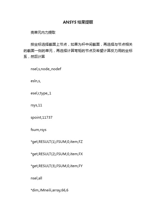
ANSYS结果提取壳单元内力提取按坐标选择截面上节点,如果为杆中间截面,再选择与节点相关的截面一侧的单元,再选择计算弯矩的节点及希望计算反力用的坐标系,然后计算nsel,s,node,,nodefesln,s,esel,r,type,,1rsys,11spoint,11737fsum,rsys*get,RESULT(1),FSUM,0,item,FZ*get,RESULT(2),FSUM,0,item,FX*get,RESULT(3),FSUM,0,item,FYnsel,all*dim,JMneili,array,66,6*do,i,1,11*do,j,1,6csys,i*10+jspoint,,0,0,0nsel,s,loc,z,0,0.4esln,s,1nsel,s,loc,z,0fsum*get,JMneili(i*6-6+j,1),fsum,,item,fx !将fsum的结果赋值*get,JMneili(i*6-6+j,2),fsum,,item,fy*get,JMneili(i*6-6+j,3),fsum,,item,fz*get,JMneili(i*6-6+j,4),fsum,,item,mx*get,JMneili(i*6-6+j,5),fsum,,item,my*get,JMneili(i*6-6+j,6),fsum,,item,mz*enddo*enddo*status,JMneili在ansys中获取变形后所有节点坐标allsel !选择所有*cfopen,'r_out','txt', !定义输出文件名*get,minnum,node,0,num,min !取最小节点编号*get,enum,node,0,count !取节点数目*do,i,1,enum,1 !循环开始*vwrite,minnum,NX(minnum),NY(minnum),NZ(minnum),ux( minnum),uy(minnum),uz(minnum)!将节点坐标及变形值写入文件中(F8.0,tl1,' ','(',f6.4,',',f6.4,',',f6.4,')',' x',f15.12,'x y',f15.12,'y z',f15.12)minnum=ndnext(minnum) !取下一个节点*enddo !循环结束从ansys结果文件导出dat文件的方法以输出结点10数据为例来说明一下,采用的是命令流的形式:/post26file,truss,rst ! 指明从哪一个结果文件中读取数据nsol,2,10,u,z ! 结点10的z方向的位移输出deriv,3,2,1,,v10 ! 结点10的z方向的速度*dim,d,,n,3 ! 定义数组n需要给出具体的数值vget,d(1,1),1 ! 存储时间向量vget,d(1,2),2 ! 存储位移向量vget,d(1,3),3 ! 存储速度向量! 以下程序段是上面三个数值结果的导出*create,temp*cfopen,truss,dat*vwrite,d(1,1),d(1,2),d(1,3)(f10.6,' ',f10.6,' ',f10.6)*cfclos*end/input,tempfini! 完成操作以后,所需要的数值结果就存储到工作目录的w.dat文件。
APDL语言汇总
Release 10.0 Documentation for ANSYS Commands ReferenceTable of Contents1. About This Manual1.1. Conventions Used in this Manual1.1.1. Product Codes1.1.2. Applicable ANSYS Products1.2. ANSYS Product Capabilities1.3. Terminology1.4. ANSYS Command Characteristics1.4.1. Data Input1.4.2. Free-Format Input1.4.3. Nonrestrictive Data Input1.4.4. Condensed Data Input1.4.5. Units1.4.6. Defaults1.4.7. File Names1.4.8. Star and Slash Commands2. Command Groupings2.1. SESSION Commands2.2. DATABASE Commands2.3. GRAPHICS Commands2.4. APDL Commands2.5. PREP7 Commands2.6. SOLUTION Commands2.7. POST1 Commands2.8. POST26 Commands2.9. AUX2 Commands2.10. AUX3 Commands2.11. AUX12 Commands2.12. AUX15 Commands2.13. RUNSTATS Commands2.14. OPTIMIZATION Commands2.15. VARIATIONAL TECHNOLOGY Commands2.16. PROBABILISTIC Design Commands2.17. DISPLAY Program Commands2.18. REDUCED Order Modeling Commands2.19. Menu-Inaccessible Commands3. Command Dictionary4. APDL CommandsI. Connection Commands~CAT5IN - Transfers a .CATPart file into the ANSYS program.~CATIAIN - Transfers a CATIA model into the ANSYS program.~CIFIN - Transfers an electronic layer geometry file in CIF format into theANSYS program.~PARAIN - Transfers a Parasolid file into the ANSYS program.~PROEIN - Transfers a Pro/ENGINEER part into the ANSYS program.~SATIN - Transfers a .SAT file into the ANSYS program.~UGIN - Transfers a Unigraphics part into the ANSYS program.II. A CommandsA - Defines an area by connecting keypoints.AADD - Adds separate areas to create a single area.AATT - Associates element attributes with the selected, unmeshed areas.ABEXTRACT - Extracts the alpha-beta damping multipliers for Rayleighdamping.ABS - Forms the absolute value of a variable.ACCAT - Concatenates multiple areas in preparation for mapped meshing.ACEL - Specifies the linear acceleration of the structure.ACLEAR - Deletes nodes and area elements associated with selected areas.ADAMS - Performs solutions and writes flexible body information to a modal neutral file (Jobname.MNF) for use in an ADAMS analysis.ADAPT - Adaptively meshes and solves a model.ADD - Adds variables.ADDAM - Specifies the acceleration spectrum computation constants for theanalysis of shock resistance of shipboard structures.ADELE - Deletes unmeshed areas.ADGL - Lists keypoints of an area that lie on a parametric degeneracy.ADRAG - Generates areas by dragging a line pattern along a path.AESIZE - Specifies the element size to be meshed onto areas.AFILLT - Generates a fillet at the intersection of two areas.AFLIST - Lists the current data in the database.AFSURF - Generates surface elements overlaid on the surface of existingsolid elements and assigns the extra node as the closest fluid element node.AGEN - Generates additional areas from a pattern of areas.AGLUE - Generates new areas by "gluing" areas.AINA - Finds the intersection of areas.AINP - Finds the pairwise intersection of areas.AINV - Finds the intersection of an area with a volume.AL - Generates an area bounded by previously defined lines.ALIST - Lists the defined areas.ALLSEL - Selects all entities with a single command.ALPFILL - Fills in an area loop within an existing 2-D area (for models imported from CAD files).ALPHAD - Defines the mass matrix multiplier for damping.AMAP - Generates a 2-D mapped mesh based on specified area corners. AMESH - Generates nodes and area elements within areas./AN3D - Specifies 3-D annotation functionsANCNTR - Produces an animated sequence of a contoured deformed shape. ANCUT - Produces an animated sequence of Q-slices.ANCYC - Applies a traveling wave animation to graphics data in a modal cyclic symmetry analysis.ANDATA - Produces a sequential contour animation over a range of results data.ANDSCL - Produces an animated sequence of a deformed shape. ANDYNA - Produces an animated sequence of contour values through substeps./ANFILE - Saves or resumes an animation sequence to or from a file. ANFLOW - Produces an animated sequence of particle flow in a flowing fluid or a charged particle traveling in an electric or magnetic field./ANGLE - Rotates the display about an axis.ANHARM - Produces a time-transient animated sequence of time-harmonic results (ANTYPE,HARMIC).ANIM - Displays graphics data in animated form.ANISOS - Produces an animated sequence of an isosurface.ANMODE - Produces an animated sequence of a mode shape.ANMRES - Performs animation of results over multiple results files in an explicit dynamic structural analysis or fluid flow analysis with remeshing. /ANNOT - Activates graphics for annotating displays (GUI).ANORM - Reorients area normals.ANSOL - Specifies averaged nodal data to be stored from the results file in the solution coordinate system.ANTIME - Produces a sequential contour animation over a range of time. ANTYPE - Specifies the analysis type and restart status./ANUM - Specifies the annotation number, type, and hot spot (GUI). AOFFST - Generates an area, offset from a given area.AOVLAP - Overlaps areas.APLOT - Displays the selected areas.APPEND - Reads data from the results file and appends it to the database. APTN - Partitions areas.ARCLEN - Activates the arc-length method.ARCOLLAPSE - Collapses specified area to a specified line segment (for models imported from CAD files).ARCTRM - Controls termination of the arc-length solution.ARDETACH - Detaches areas from neighboring geometrical entities (formodels imported from CAD files).AREAS - Specifies "Areas" as the subsequent status topic.AREFINE - Refines the mesh around specified areas.AREMESH - Generates an area in which to create a new mesh for rezoning.AREVERSE - Reverses the normal of an area, regardless of its connectivityor mesh status.ARFILL - Creates an area based on a set of singly-connected lines (formodels imported from CAD files).ARMERGE - Merges two or more singly-connected adjacent areas (formodels imported from CAD files).AROTAT - Generates cylindrical areas by rotating a line pattern about anaxis.ARSCALE - Generates a scaled set of areas from a pattern of areas.ARSPLIT - Splits an area between two keypoints (for models imported fromCAD files).ARSYM - Generates areas from an area pattern by symmetry reflection.ASBA - Subtracts areas from areas.ASBL - Subtracts lines from areas.ASBV - Subtracts volumes from areas.ASBW - Subtracts the intersection of the working plane from areas (dividesareas).ASEL - Selects a subset of areas.ASKIN - Generates an area by "skinning" a surface through guiding lines.ASLL - Selects those areas containing the selected lines.ASLV - Selects those areas contained in the selected volumes./ASSIGN - Reassigns a file name to an ANSYS file identifier.ASUB - Generates an area using the shape of an existing area.ASUM - Calculates and prints geometry statistics of the selected areas.ATAN - Forms the arctangent of a complex variable.ATRAN - Transfers a pattern of areas to another coordinate system.ATYPE - Specifies "Analysis types" as the subsequent status topic./AUTO - Resets the focus and distance specifications to "automaticallycalculated."AUTOTS - Specifies whether to use automatic time stepping or load stepping./AUX2 - Enters the binary file dumping processor./AUX3 - Enters the results file editing processor./AUX12 - Enters the radiation processor./AUX15 - Enters the IGES file transfer processor.AVPRIN - Specifies how principal and vector sums are to be calculated.AVRES - Specifies how results data will be averaged when PowerGraphics is enabled./AXLAB - Labels the X and Y axes on graph displays.III. B Commands/BATCH- Sets the program mode to "batch."BCSOPTION - Sets memory option for the sparse solver.BELLOW - Defines a bellows in a piping run.BEND - Defines a bend in a piping run.BETAD - Defines the stiffness matrix multiplier for damping.BF - Defines a nodal body force load.BFA - Defines a body force load on an area.BFADELE - Deletes body force loads on an area.BFALIST - Lists the body force loads on an area.BFCUM - Specifies that nodal body force loads are to be accumulated. BFDELE - Deletes nodal body force loads.BFE - Defines an element body force load.BFECUM - Specifies whether to ignore subsequent element body force loads. BFEDELE - Deletes element body force loads.BFELIST - Lists the element body force loads.BFESCAL - Scales element body force loads.BFINT - Activates the body force interpolation operation.BFK - Defines a body force load at a keypoint.BFKDELE - Deletes body force loads at a keypoint.BFKLIST - Lists the body force loads at keypoints.BFL - Defines a body force load on a line.BFLDELE - Deletes body force loads on a line.BFLIST - Lists the body force loads on nodes.BFLLIST - Lists the body force loads on a line.BFSCALE - Scales body force loads at nodes.BFTRAN - Transfers solid model body force loads to the finite element model.BFUNIF - Assigns a uniform body force load to all nodes.BFV - Defines a body force load on a volume.BFVDELE - Deletes body force loads on a volume.BFVLIST - Lists the body force loads on a volume.BIOOPT - Specifies "Biot-Savart options" as the subsequent status topic. BIOT - Calculates the Biot-Savart source magnetic field intensity.BLC4 - Creates a rectangular area or block volume by corner points.BLC5 - Creates a rectangular area or block volume by center and corner points.BLOCK - Creates a block volume based on working plane coordinates. BOOL - Specifies "Booleans" as the subsequent status topic.BOPTN - Specifies Boolean operation options.BRANCH - Defines the starting point for a piping branch.BSAX - Specifies the axial strain and axial force relationship for beam sections.BSMD - Specifies mass density for a nonlinear general beam section.BSM1 - Specifies the bending curvature and moment relationship in plane XZ for beam sections.BSM2 - Specifies the bending curvature and moment relationship in plane XY for beam sections.BSPLIN - Generates a single line from a spline fit to a series of keypoints.BSS1 - Specifies the transverse shear strain and force relationship in plane XZ for beam sections.BSS2 - Specifies the transverse shear strain and force relationship in plane XY for beam sections.BSTE - Specifies a thermal expansion coefficient for a nonlinear generalbeam section.BSTQ - Specifies the cross section twist and torque relationship for beamsections.BTOL - Specifies the Boolean operation tolerances.BUCOPT - Specifies buckling analysis options.IV. C CommandsC*** - Places a comment in the output.CALC - Specifies "Calculation settings" as the subsequent status topic.CBDOF - Activates cut boundary interpolation (for submodeling).CDOPT - Specifies format to be used for archiving geometry.CDREAD - Reads a file of solid model and database information into thedatabase.CDWRITE - Writes geometry and load database items to a file.CE - Defines a constraint equation relating degrees of freedom.CECHECK- Check constraint equations and couplings for rigid bodymotions.CECMOD - Modifies the constant term of a constraint equation duringsolution.CECYC - Generates the constraint equations for a cyclic symmetry analysisCEDELE - Deletes constraint equations.CEINTF - Generates constraint equations at an interface.CELIST - Lists the constraint equations.CENTER - Defines a node at the center of curvature of 2 or 3 nodes.CEQN - Specifies "Constraint equations" as the subsequent status topic.CERIG - Defines a rigid region.CESGEN - Generates a set of constraint equations from existing sets.CFACT - Defines complex scaling factors to be used with operations./CFORMAT - Controls the graphical display of alphanumeric characterstrings for parameters, components, assemblies, and tables.CGLOC - Specifies the origin location of the acceleration coordinate system.CGOMGA - Specifies the rotational velocity of the global origin.CHECK - Checks current database items for completeness.CHKMSH - Checks area and volume entities for previous meshes.CIRCLE - Generates circular arc lines./CLABEL - Specifies contour labeling./CLEAR - Clears the database.CLOCAL - Defines a local coordinate system relative to the active coordinate system.CLOG - Forms the common log of a variable/CLOG - Copies the session log file to a named file.CLRMSHLN - Clears meshed entities.CM - Groups geometry items into a component.CMACEL - Specifies the translational acceleration of an element component /CMAP - Changes an existing or creates a new color mapping table. CMATRIX - Performs electrostatic field solutions and calculates the self and mutual capacitances between multiple conductors.CMDELE - Deletes a component or assembly definition.CMDOMEGA - Specifies the rotational acceleration of an element component about a user-defined rotational axis.CMEDIT - Edits an existing assembly.CMGRP - Groups components and assemblies into an assembly.CMLIST - Lists the contents of a component or assembly.CMMOD - Modifies the specification of a component.CMOMEGA - Specifies the rotational velocity of an element component about a user-defined rotational axis.CMPLOT - Plots the entities contained in a component or assembly. CMSEL - Selects a subset of components and assemblies.CMSFILE - Specifies a list of component mode synthesis (CMS) results files for plotting results on the assembly.CMSOPT - Specifies component mode synthesis (CMS) analysis options. CNCHECK - Provides and/or adjusts the initial status of contact pairs. CNVTOL - Sets convergence values for nonlinear analyses./COLOR - Specifies the color mapping for various items./COM - Places a comment in the output.COMPRESS - Deletes all specified sets.CON4 - Creates a conical volume anywhere on the working plane.CONE - Creates a conical volume centered about the working plane origin. /CONFIG - Assigns values to ANSYS configuration parameters.CONJUG - Forms the complex conjugate of a variable./CONTOUR - Specifies the uniform contour values on stress displays./COPY - Copies a file.CORIOLIS - Applies the Coriolis effect to a rotating structure.COUPLE - Specifies "Node coupling" as the subsequent status topic. COVAL - Defines PSD cospectral values.CP - Defines (or modifies) a set of coupled degrees of freedom.CPCYC - Couples the two side faces of a cyclically symmetric model for loadings that are the same on every segment.CPDELE - Deletes coupled degree of freedom sets.CPINTF - Defines coupled degrees of freedom at an interface./CPLANE - Specifies the cutting plane for section and capped displays.CPLGEN - Generates sets of coupled nodes from an existing set.CPLIST - Lists the coupled degree of freedom sets.CPMERGE - Merges different couple sets with duplicate degrees of freedom into one couple set.CPNGEN - Defines, modifies, or adds to a set of coupled degrees of freedom.CPSGEN - Generates sets of coupled nodes from existing sets.CQC - Specifies the complete quadratic mode combination method.CRPLIM - Specifies the creep criterion for automatic time stepping.CS - Defines a local coordinate system by three node locations.CSCIR - Locates the singularity for non-Cartesian local coordinate systems.CSDELE - Deletes local coordinate systems.CSKP - Defines a local coordinate system by three keypoint locations.CSLIST - Lists coordinate systems.CSWPLA - Defines a local coordinate system at the origin of the workingplane.CSYS - Activates a previously defined coordinate system./CTYPE - Specifies the type of contour display.CURR2D - Calculates current flow in a 2-D conductor.CUTCONTROL - Controls time-step cutback during a nonlinear solution./CVAL - Specifies nonuniform contour values on stress displays.CVAR - Computes covariance between two quantities./CWD - Changes the current working directory./CYCEXPAND - Graphically expands displacements, stresses and strains of a cyclically symmetric model.CYCLIC - Specifies a cyclic symmetry analysis.CYCOPT - Specifies solution options for a cyclic symmetry analysis.CYCPHASE - Provides tools for determining minimum and maximumpossible result values from frequency couplets produced in a modal cyclicsymmetry analysis.CYL4 - Creates a circular area or cylindrical volume anywhere on theworking plane.CYL5 - Creates a circular area or cylindrical volume by end points.CYLIND - Creates a cylindrical volume centered about the working planeorigin.CZDEL - Edits or clears cohesive zone sections.CZMESH - Create and mesh an interface area composed of cohesive zoneelements.V. D CommandsD - Defines DOF constraints at nodes.DA - Defines DOF constraints on areas.DADELE - Deletes DOF constraints on an area.DALIST - Lists the DOF constraints on an area.DAMORPH - Move nodes in selected areas to conform to structural displacements.DATA - Reads data records from a file into a variable.DATADEF - Specifies "Directly defined data status" as the subsequent status topic.DCGOMG - Specifies the rotational acceleration of the global origin. DCUM - Specifies that DOF constraint values are to be accumulated. DCVSWP - Performs a DC voltage sweep on a ROM element.DDELE - Deletes degree of freedom constraints.DEACT - Specifies "Element birth and death" as the subsequent status topic. DECOMP - Decomposes the model into domains used by Distributed ANSYSDEFINE - Specifies "Data definition settings" as the subsequent status topic. DELETE - Specifies sets in the results file to be deleted before postprocessing./DELETE - Deletes a file.DELTIM - Specifies the time step sizes to be used for this load step. DEMORPH - Move nodes in selected elements to conform to structural displacements.DERIV - Differentiates a variable.DESIZE - Controls default element sizes.DESOL - Defines or modifies solution results at a node of an element. DETAB - Modifies element table results in the database./DEVDISP - Controls graphics device options./DEVICE - Controls graphics device options.DIG - Digitizes nodes to a surface.DIGIT - Specifies "Node digitizing" as the subsequent status topic. DISPLAY - Specifies "Display settings" as the subsequent status topic./DIST - Specifies the viewing distance for magnifications and perspective. DJ - Specify displacement (or rotation) boundary conditions on the components of relative motion of a joint element.DJDELE - Deletes displacement (or rotation) boundary conditions on the components of relative motion of a joint element.DJLIST - Lists boundary conditions applied to joint elements.DK - Defines DOF constraints at keypoints.DKDELE - Deletes DOF constraints at a keypoint.DKLIST - Lists the DOF constraints at keypoints.DL - Defines DOF constraints on lines.DLDELE - Deletes DOF constraints on a line.DLIST - Lists DOF constraints.DLLIST - Lists DOF constraints on a line.DMOVE - Digitizes nodes on surfaces and along intersections.DMPEXT - Extracts modal damping coefficients in a specified frequency range.DMPRAT - Sets a constant damping ratio.DNSOL - Defines or modifies solution results at a node.DOF - Adds degrees of freedom to the current DOF set.DOFSEL - Selects a DOF label set for reference by other commands.DOMEGA - Specifies the rotational acceleration of the structure.DSCALE - Scales DOF constraint values./DSCALE - Sets the displacement multiplier for displacement displays.DSET - Sets the scale and drawing plane orientation for a digitizing tablet.DSUM - Specifies the double sum mode combination method.DSURF - Defines the surface upon which digitized nodes lie.DSYM - Specifies symmetry or antisymmetry DOF constraints on nodes.DSYS - Activates a display coordinate system for geometry listings and plots.DTRAN - Transfers solid model DOF constraints to the finite element model.DUMP - Dumps the contents of a binary file./DV3D - Sets 3-D device option modes.DVMORPH - Move nodes in selected volumes to conform to structuraldisplacements.DYNOPT - Specifies "Dynamic analysis options" as the subsequent statustopic.VI. E CommandsE - Defines an element by node connectivity.EALIVE - Reactivates an element (for the birth and death capability).EDADAPT - Activates adaptive meshing in an explicit dynamic analysis.EDALE - Assigns mesh smoothing to explicit dynamic elements that use the ALE formulation.EDASMP - Creates a part assembly to be used in an explicit dynamicanalysis.EDBOUND - Defines a boundary plane for sliding or cyclic symmetry.EDBX - Creates a box shaped volume to be used in a contact definition forexplicit dynamics.EDBVIS - Specifies global bulk viscosity coefficients for an explicitdynamics analysis.EDCADAPT - Specifies adaptive meshing controls for an explicit dynamicanalysis.EDCGEN - Specifies contact parameters for an explicit dynamics analysis.EDCLIST - Lists contact entity specifications in an explicit dynamicsanalysis.EDCMORE - Specifies additional contact parameters for a given contactdefinition in an explicit dynamic analysis.EDCNSTR - Defines various types of constraints for an explicit dynamicanalysis.EDCONTACT - Specifies contact surface controls for an explicit dynamicsanalysis.EDCPU - Specifies CPU time limit for an explicit dynamics analysis.EDCRB - Constrains two rigid bodies to act as one in an explicit dynamics analysis.EDCSC - Specifies whether to use subcycling in an explicit dynamics analysis.EDCTS - Specifies mass scaling and scale factor of computed time step for an explicit dynamics analysis.EDCURVE - Specifies data curves for an explicit dynamic analysis. EDDAMP - Defines mass weighted (Alpha) or stiffness weighted (Beta) damping for an explicit dynamics model.EDDBL - Selects a numerical precision type of the explicit dynamics analysis. EDDC - Deletes or deactivates/reactivates contact surface specifications in an explicit dynamic analysis.EDDRELAX - Activates initialization to a prescribed geometry or dynamic relaxation for the explicit analysis.EDDUMP - Specifies output frequency for the explicit dynamic restart file (d3dump).EDELE - Deletes selected elements from the model.EDENERGY - Specifies energy dissipation controls for an explicit dynamics analysis.EDFPLOT - Allows plotting of explicit dynamics forces and other load symbols.EDGCALE - Defines global ALE controls for an explicit dynamic analysis. /EDGE - Displays only the "edges" of an object.EDHGLS - Specifies the hourglass coefficient for an explicit dynamics analysis.EDHIST - Specifies time-history output for an explicit dynamic analysis. EDHTIME - Specifies the time-history output interval for an explicit dynamics analysis.EDINT - Specifies number of integration points for explicit shell and beam output.EDIPART - Defines inertia for rigid parts in an explicit dynamics analysis. EDIS- Specifies stress initialization in an explicit dynamic full restart analysis.EDLCS - Defines a local coordinate system for use in explicit dynamics analysis.EDLOAD - Specifies loads for an explicit dynamics analysis.EDMP - Defines material properties for an explicit dynamics analysis. EDNB - Defines a nonreflecting boundary in an explicit dynamic analysis. EDNDTSD - Allows smoothing of noisy data for explicit dynamics analyses and provides a graphical representation of the data.EDNROT - Applies a rotated coordinate nodal constraint in an explicit dynamics analysis.EDOPT - Specifies the type of output for an explicit dynamics analysis.EDOUT - Specifies time-history output (ASCII format) for an explicit dynamics analysis.EDPART - Configures parts for an explicit dynamics analysis.EDPC - Selects and plots explicit dynamic contact entities.EDPL - Plots a time dependent load curve in an explicit dynamic analysis. EDPVEL - Applies initial velocities to parts or part assemblies in an explicit dynamic analysis.EDRC - Specifies rigid/deformable switch controls in an explicit dynamic analysis.EDRD - Switches a part from deformable to rigid or from rigid to deformable in an explicit dynamic analysis.EDREAD - Reads explicit dynamics output into variables for time-history postprocessing.EDRI - Defines inertia properties for a new rigid body that is created when a deformable part is switched to rigid in an explicit dynamic analysis.EDRST - Specifies the output interval for an explicit dynamic analysis. EDRUN - Specify LS-DYNA serial or parallel processing.EDSHELL - Specifies shell computation controls for an explicit dynamics analysis.EDSOLV - Specifies "explicit dynamics solution" as the subsequent status topic.EDSP - Specifies small penetration checking for contact entities in an explicit dynamic analysis.EDSTART - Specifies status (new or restart) of an explicit dynamics analysis. EDTERM - Specifies termination criteria for an explicit dynamic analysis. EDTP - Plots explicit elements based on their time step size.EDVEL - Applies initial velocities to nodes or node components in an explicit dynamic analysis.EDWELD - Defines a massless spotweld or generalized weld for use in an explicit dynamic analysis.EDWRITE - Writes explicit dynamics input to an LS-DYNA input file./EFACET - Specifies the number of facets per element edge for PowerGraphics displays.EGEN - Generates elements from an existing pattern.EINTF - Defines two-node elements between coincident or offset nodes. EKILL - Deactivates an element (for the birth and death capability).ELEM - Specifies "Elements" as the subsequent status topic.ELIST - Lists the elements and their attributes.EMAGERR - Calculates the relative error in an electrostatic or electromagnetic field analysis.EMATWRITE - Forces the writing of all the element matrices to File.EMAT. EMF - Calculates the electromotive force (emf), or voltage drop along a predefined path.EMFT - Summarizes electromagnetic forces and torques.EMID - Adds or removes midside nodes.EMIS - Specifies emissivity as a material property for the Radiation Matrix method.EMODIF - Modifies a previously defined element.EMORE - Adds more nodes to the just-defined element.EMSYM - Specifies circular symmetry for electromagnetic sources. EMTGEN- Generates a set of TRANS126 elements.EMUNIT - Specifies the system of units for magnetic field problems.EN - Defines an element by its number and node connectivity. ENDRELEASE - Specifies degrees of freedom to be decoupled for end release.ENGEN - Generates elements from an existing pattern.ENORM - Reorients shell element normals or line element node connectivity. ENSYM - Generates elements by symmetry reflection./EOF - Exits the file being read.EORIENT - Reorients solid element normals.EPLOT - Produces an element display.EQSLV- Specifies the type of equation solver.ERASE - Explicitly erases the current display./ERASE - Specifies that the screen is to be erased before each display. EREAD - Reads elements from a file.EREFINE - Refines the mesh around specified elements.ERESX - Specifies extrapolation of integration point results.ERNORM - Controls error estimation calculations.ERRANG - Specifies the element range to be read from a file.ESCHECK - Perform element shape checking for a selected element set. ESEL - Selects a subset of elements./ESHAPE - Displays elements with shapes determined from the real constants or section definition.ESIZE - Specifies the default number of line divisions.ESLA - Selects those elements associated with the selected areas.ESLL - Selects those elements associated with the selected lines.ESLN - Selects those elements attached to the selected nodes.ESLV - Selects elements associated with the selected volumes.ESOL - Specifies element data to be stored from the results file.ESORT - Sorts the element table.ESSOLV - Performs a coupled electrostatic-structural analysis.ESTIF - Specifies the matrix multiplier for deactivated elements.ESURF - Generates elements overlaid on the free faces of existing selected elements.ESYM - Generates elements from a pattern by a symmetry reflection.ESYS - Sets the element coordinate system attribute pointer.ET - Defines a local element type from the element library.ETABLE - Fills a table of element values for further processing.。
ANSYS APDL命令汇总
ANSYS APDL命令汇总AA,P1,P2,P3,P4,P5,P6,P7,P8,P9此命令用已知的一组关键点点(P1~P9)来定义面(Area),最少使用三个点才能围成面,同时产生转围绕些面的线。
点要依次序输入,输入的顺序会决定面的法线方向。
如果超过四个点,则这些点必须在同一个平面上。
Menu Paths:Main Menu>Preprocessor>Create>Arbitrary>Through KPsABBR*ABBR,Abbr,String--定义一个缩略语.Abbr:用来表示字符串"String"的缩略语,长度不超过8个字符.String:将由"Abbr"表示的字符串,长度不超过60个字符.ABBRESABBRES,Lab,Fname,Ext-从一个编码文件中读出缩略语.Lab:指定读操作的标题,NEW:用这些读出的缩略语重新取代当前的缩略语(默认)CHANGE:将读出的缩略语添加到当前缩略语阵列,并替代现存同名的缩略语.Ext:如果"Fname"是空的,则缺省的扩展命是"ABBR".ABBSAVABBSAV,Lab,Fname,Ext-将当前的缩略语写入一个文本文件里Lab:指定写操作的标题,若为ALL,表示将所有的缩略语都写入文件(默认ADDadd, ir, ia,ib,ic,name,--,--,facta, factb, factc将ia,ib,ic变量相加赋给ir变量ir, ia,ib,ic:变量号name: 变量的名称ADELEAdele,na1,na2,ninc,kswp !kswp=0时只删除掉面积本身,=1时低单元点一并删除。
ADRAGAdrag, nl1,nl2,nl3,nl4,nl5,nl6, nlp1,nlp2,nlp3,nlp4,nlp5,nlp6 !面积的建立,沿某组线段路径,拉伸而成AFILLTAfillt,na1,na2,rad !建立圆角面积,在两相交平面间产生曲面,rad为半径。
ANSYS_数据文件读写的APDL命令详解及实例
ANSYS_数据⽂件读写的APDL命令详解及实例ANSYS 数据⽂件读写的APDL命令详解及实例作者:huright⼀ FORTRAN数据格式I格式(⼜叫整数格式)⼀般形式:Iw 或:Iw.m其中:w ⼀个数据占的位数宽度(⼜称“字段宽度”),m 需要输出的最少数字位数。
例1:(1)数字在指定的区域内向右端靠齐,如果数字位数⽐指定的字段宽度w⼩,则左边补以空格。
负数的符号也包含在字段宽度内。
(2)如果数字的位数超过了规定的字段宽度w,则不输出有效数据,⽽在该字段宽度范围内充满“*”符号。
(3)如果数字的位数超过了m,则按实际应输出的位数输出(但条件是不能超过w)。
m 不包括负号所占的⼀列。
F格式(⼜叫⼩数型格式)⼀般形式:Fw.dw 各数值占的总位数 d 输出数据的⼩数位数(⼩数点后的位数)。
例1:(1)数字在指定的区域内向右端靠齐,如果数字位数(含⼩数点和符号位)⽐指定的字段宽度w⼩,则左边补以空格;如果数字的位数超过了规定的字段宽度w,则不输出有效数据,⽽在该字段宽度范围内充满“*”符号。
(2)如果数据的⼩数位数⽐指定的⼩数位数d⼩,则在⼩数右边补0以凑⾜d位;如果⼩数位数⼤于d位,则输出时多于的⼩数位数按“四舍五⼊”规则舍去。
(3)假设b为数据整数部分的位数,则应使w≥b+d+1(⼩数点占⼀列),如果输出负数,则应保证w≥b+d+2(⼩数点和负号各占⼀列)。
(4)⽤F格式输出时应注意,由于难以事先确切估计出数据的⼤⼩,输出⼤的数时容易产⽣“宽度不够”的错误(由于w不够⼤),输出⼩的数时会出现丢掉有⽤数字的情况(由于d不够⼤⽽将后⾯的数字截去),这就是“⼤数印错,⼩数印丢”。
E格式(⼜叫指数型格式)⼀般形式:w.dw 各数值占的总位数,d 输出数据的⼩数位数(⼩数点后的位数)。
例1:(1)采取标准化的指数形式输出⼀个实数,d为以指数形式出现的数据的数字部分的⼩数位数。
(2)指数部分⼀般占4列,其中字母“E”和指数的符号各占⼀列,指数2列。
ANSYS经典APDL编程
ANSYS经典APDL编程在使⽤ANSYS的过程中的⼀些经验总结:Ansys Workbench 虽然进⼊UI阶段,但是语⾔命令仍然是其基础核⼼。
1.ANSYS中的⼀些关键概念的理解;参数化程序设计语⾔(APDL) 参数化程序设计语⾔(APDL:ANSYS Parametric Design Language)实质上由类似于FORTRAN77的程序设计语⾔部分和1000多条ANS YS命令组成。
其中,程序设计语⾔部分与其它编程语⾔⼀样,具有参数、数组表达式、函数、流程控制(循环与分⽀)、重复执⾏命令、缩写、宏以及⽤户程序等。
标准的AN SYS程序运⾏是由1000多条命令驱动的,这些命令可以写进程序设计语⾔编写的程序,命令的参数可以赋确定值,也可以通过表达式的结果或参数的⽅式进⾏赋值。
从ANSYS命令的功能上讲,它们分别对应ANSYS分析过程中的定义⼏何模型、划分单元⽹格、材料定义、添加载荷和边界条件、控制和执⾏求解和后处理计算结果等指令。
⽤户可以利⽤程序设计语⾔将ANSYS命令组织起来,编写出参数化的⽤户程序,从⽽实现有限元分析的全过程,即建⽴参数化的CAD模型、参数化的⽹格划分与控制、参数化的材料定义、参数化的载荷和边界条件定义、参数化的分析控制和求解以及参数化的后处理。
宏是具有某种特殊功能的命令组合,实质上是参数化的⽤户⼩程序,可以当作ANSY S的命令处理,可以有输⼊参数或没有输⼊参数。
缩写是某条命令或宏的替代名称,它与被替代命令或宏存在⼀⼀对应的关系,在AN SYS中⼆者是完全等同的,但缩写更符合⽤户习惯,更易于记忆,减少敲击键盘的次数。
ANSYS⼯具条就是⼀个很好的缩写例⼦。
⽤户界⾯设计语⾔(UIDL) 标准ANSYS交互图形界⾯可以驱动ANSYS命令,提供命令的各类输⼊参数接⼝和控制开关,⽤户在图形驱动的级别上进⾏有限元分析,整个过程变得直观轻松。
⽤户图形界⾯设计语⾔(UIDL)就是编写或改造ANSYS图形界⾯的专⽤设计语⾔,主要完成以下三种图形界⾯的设计: 主菜单系统及菜单项对话框和拾取对话框帮助系统通过⽤户界⾯设计语⾔(UIDL),⽤户可以在扩充ANSYS功能的同时建⽴起对应的图形驱动界⾯,如在主菜单的某位置增加菜单项,设计对应的对话框、拾取对话框,实现参数的输⼊和其它程序运⾏的控制,同时提供相应的联机帮助,使操作者能⽅便地获取系统帮助。
ANSYS讲义第09讲-参数化设计语言Parametric Design Language (APDL)
Dec,2,2004
湖南大学土木学院
L9-8
使用工具条-工具条嵌套
• 如果有很多按钮,将其放在一个工具条上会显得太拥挤,同时ANSYS也 要求每个工具条不超过100个按钮。——解决办法是工具条嵌套。 工具条嵌套意味着:一个工具条的某个按钮指向的是另一个工具条,而不 是像通常那样指向命令、函数或者宏。 按照这种方式,理论上可以建立无限个缩略词,即产生无限的按钮。 在每个工具条上加上一个RETURN按钮,以返回上一级工具条(好习惯 )。
湖南大学土木学院
L9-23
字符参量
• 字符参量代表不超过8个字符的字符串,字符参量的定义、修改和删除与标量参 量的基本一致。 Remember:定义字符参量时用单引号(‘’)括起来。 字符参量的典型用法是提供文件名及其扩展名。
• •
• 用法: 1、当某个命令需要输入字符时,可以用字符参量代替:如调用宏 NAME=‘MyMACRO’ ABC=‘SX’ *USE,NAME,ABC 或 *USE,NAME,’SX’ 2、判断: EF=‘NO’ *IF,EF,NE,’YES’,THENDec,2 Nhomakorabea2004
湖南大学土木学院
L9-15
赋ANSYS提供的值给参量(续)
• GUI方式: Utility Menu>Parameters>Get Scalar Data
参量名 提取的实体号 提取的结果
Dec,2,2004
湖南大学土木学院
L9-16
利用ANSYS内嵌的函数进行赋值
•
对于某些参量,可以利用内嵌函数来代替*GET命令。内嵌函数返回参量的 值并直接用于当前的计算中。这样做就不必先赋值给参量,而在运行中直接 调用该参量,省去了中间参量。 如:计算两个结点的中点的位置,如果采用*GET命令,则需输入: *GET,L1,NODE,1,LOC,X *GET,L2,NODE,2,LOC,X MID=(L1+L2)/2 而用内嵌函数时则变得很简单: MID=(NX(1)+NX(2))/2
- 1、下载文档前请自行甄别文档内容的完整性,平台不提供额外的编辑、内容补充、找答案等附加服务。
- 2、"仅部分预览"的文档,不可在线预览部分如存在完整性等问题,可反馈申请退款(可完整预览的文档不适用该条件!)。
- 3、如文档侵犯您的权益,请联系客服反馈,我们会尽快为您处理(人工客服工作时间:9:00-18:30)。
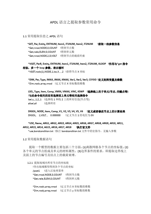
APDL语言之提取参数常用命令
1.1常用提取信息之APDL语句
*GET, Par, Entity, ENTNUM, Item1, IT1NUM, Item2, IT2NUM !获取一些参数信息
*Get,nnod,NODE,0,COUNT !得到节点数
*Get,nele,ELEM,0,COUNT !得到单元数
*Get,nnod,NODE,2,D,VOLT !得到节点的载荷约束
*VGET, ParR, Entity, ENTNUM, Item1, IT1NUM, Item2, IT2NUM, KLOOP !作用与*get指令相似,多一个loop参数,表示循环
*VGET,nodx(1),NODE,1,loc,X, , ,2 !获得节点X坐标
*DIM, Par, Type, IMAX, JMAX, KMAX, Var1, Var2, Var3, CSYSID !定义矩阵变量及维数
*Dim,nodx,array,nnod !定义节点X坐标数组维数
LSEL, Type, Item, Comp, VMIN, VMAX, VINC, KSWP !选择线上的子单元(节点,关键点等) !与此命令相关的还有选择面上单元等相关选择指令
lsel,s,,,1,2,,1 !选择线1和线2上的所有信息(节点等)
allsel,all !选择所有
DNSOL, NODE, Item, Comp, V1, V2, V3, V4, V5, V6 !定义或者修改节点上的计算结果DNSOL, 1,VOLT, , 0.000000 !定义节点1的电位为0V
*USE, Name, ARG1, ARG2, ARG3, ARG4, ARG5, ARG6, ARG7, ARG8, ARG9, AR10, AR11, AR12, AR13, AR14, AG15, AR16, AR17, AR18 !执行宏文件
*use,bondcondition.txt !执行bondcondition.txt文件中的宏指令,无输入参数
1.2常用提取数据语句
提取一个模型的数据主要包括三个方面:(1)离散网格各个节点的坐标值;(2)各个单元的节点组成及单元的材料属性;(3)边界条件的要求,即提取边界线上及面上的节点编号及结点上的载荷束缚。
1.2.1 提取场域内所有节点的坐标值
!导出场域模型得到各个节点的坐标
/post1 !进入后处理菜单
*Get,nnod,NODE,0,COUNT !得到节点数
*Get,nele,ELEM,0,COUNT !得到单元数
*Dim,nodx,array,nnod !定义节点X坐标数组维数
*Dim,nody,array,nnod !定义节点y坐标数组维数
*VGET,nodx(1),NODE,1,loc,X, , ,2 !获得节点X坐标
*VGET,nody(1),NODE,1,loc,Y, , ,2 !获得节点Y坐标
*cfopen,eleNodNum,txt !新建文件存储单元数与节点数
*vwrite,nele,nnod
(F10.0,F10.0) !数据格式
*cfclose
*cfopen,nodeLoc,txt !新建文件存储节点坐标
*vwrite,sequ,nodx(1),nody(1)
(F8.0,2F17.9)
*cfclos
1.2.2 提取场域内所有单元的单元信息(组成单元的节点号,单元类型,材料属性,实常数)
/post1 !提取三角形单元的单元信息
*Get,nnod,NODE,0,COUNT
*Get,nele,ELEM,0,COUNT
*Dim,n1,array,nELE
*Dim,n2,array,nELE
*Dim,n3,array,nELE
*Dim,m1,array,nELE
*Dim,m2,array,nELE
*Dim,m3,array,nELE
*VGET,n1(1),ELEM,1,NODE,1, , ,2
*VGET,n2(1),ELEM,1,NODE,2, , ,2
*VGET,n3(1),ELEM,1,NODE,3, , ,2
*VGET,M1(1),ELEM,1,ATTR,TYPE, , ,2
*VGET,M2(1),ELEM,1,ATTR,MAT, , ,2
*VGET,M3(1),ELEM,1,ATTR,REAL, , ,2
*CFOPEN,elementPro,txt
*VWRITE,sequ,n1(1),n2(1),n3(1),m1(1),m2(1),m3(1)
(F8.0,6F10.0)
*CFCLOS
1.2.3 提取第一类边界条件信息,及提取边界上的载荷约束情况
/post1
lsel,s,,,2,,,1
*get,nlnod,node,0,count
*get,nlmin,node,0,num,min
*dim,bonline,array,nlnod
*Dim,nodv,array,nlnod
n0=nlmin
bonline(1)=n0
*do,i,2,nlnod
n0=ndnext(n0)
bonline(i)=n0
*enddo
allsel,all
*do,i,1,nlnod
*GET,nodv(i),NODE,bonline(i),D,VOLT
*enddo
*cfopen,bdyCon,txt
*vwrite,sequ,bonline(1),nodv(1)
(F8.0,2F10.0)
*cfclose
参考文献:
[1] 龚曙光等ANSYS 参数化编程与命令手册机械工业出版社.
[2] 周宁. ANSYS-APDL高级工程应用实例分析与二次开发北京:中国水利水电出版社,2007
[3] 王泽忠. 简明电磁场数值计算
2 计算实例
2.1 计算模型
=100V
ϕ
=0V
图2.1 计算模型
2.2 计算结果
2.2 ansys计算电势云图图2.3 matlab计算过后ansys显示
图2.4 电场强度E矢量图图2.5 电位移矢量D矢量图
图2.6 matlab等位云图
问题:能否通过得到节点上的电位值,通过ansys直接得到各个节点上的D
及
E
值;。