欧姆龙温控表e5ec参数说明书
E5CSL E5CWL温度控制器使用说明书

E5CSL/E5CWL T emperature Controller Instruction Manual Thank you for purchasing the OMRON E5CSL/E5CWL Temperature Controller. This manual describes the functions, performance, and application methods needed for optimum use of the product.Please observe the following items when using the product.• This product is designed for use by qualified personnel with a knowledge of electrical systems.• Before using the product, thoroughly read and understand this manual to ensure correct use.• Keep this manual in a safe location so that it is available for reference whenever required.©All Rights Reserved Suitability for Use OMRON shall not be responsible for conformity with any standards, codes, or regulations that apply to the combination of the products in the customer's application or use of the product. Take all necessary steps to determine the suitability of the product for the systems, machines, and equipment with which it will be used.Know and observe all prohibitions of use applicable to this product.NEVER USE THE PRODUCTS FOR AN APPLICATION INVOLVING SERIOUS RISK TO LIFE OR PROPERTY WITHOUT ENSURING THAT THE SYSTEM AS A WHOLE HAS BEEN DESIGNED TO ADDRESS THE RISKS, AND THAT THE OMRON PRODUCT IS PROPERLY RATED AND INSTALLED FOR THE INTENDED USE WITHIN THE OVERALL EQUIPMENT OR SYSTEM.See also product catalog for Warranty and Limitation of Liability.CAUTION Do not touch the terminals while power is being supplied. Doing so may occasionally result in minor injury due to electric shock.Do not allow pieces of metal, wire clippings, or fine metallic shavings or filings from installation to enter the product. Doing so may occasionally result in electric shock, fire, or malfunction.Do not use the product where subject to flammable or explosive gas. Otherwise, minor injury from explosion mayoccasionally occur.Never disassemble, modify, or repair the product or touch any of the internal parts. Minor electric shock, fire, or malfunction may occasionally occur. If the output relays are used past their life expectancy, contact fusing or burning may occasionally occur. Always consider the application conditions and use the output relays within their rated load and electrical life expectancy. The life expectancy of output relays varies considerably with the output load and switching conditions.Tighten the terminal screws to between 0.74 and 0.90 N·m. Loose screws may occasionally result in fire.Set the parameters of the product so that they are suitable for the system being controlled. If they are not suitable, unexpected operation may occasionally result in property damage or accidents.EN Models with Single Display Models with Dual Display E5CSL- R Relay output: 250 VAC, 3 A Q Voltage output (for driving SSR): 12 VDC, 21 mA Control output 131Sensor type 31 Relay output: 250 VAC, 1 A (resistive load)Alarm (E5CWL only)2E5CWL- 1123• Insert the Controller through the hole in the panel. Push the adapter on from therear to secure the Controller.• Make sure that the surrounding temperature does not exceed the allowable operating temperature given in the specifications, especially when two or more Controllers are mounted.• The voltage output (control output) is not electrically isolated from the internalwiring. One or the other of the control output terminals must therefore be leftungrounded when using a grounded thermocouple thermometer. (If both are grounded, measurements will be unreliable due to sneak current.)Individual Mounting Side-by-side Mounting TC Thermocouple (K, J, T, R, or S)P Platinum resistance thermometer (Pt100)The standby sequence is cleared when the alarm OFF condition has been met.The standby sequence is started again when any of the following conditions is met.• Operation is started (power is turned ON or operation is switched from stop to run).• The alarm value is changed.• The temperature input offset is changed.• The set point is changed.Standby sequence clearedAlarm value Alarm with standby sequenceProcess value TimeAlarm without standby sequence Example: Deviation Lower Limit Standby Sequence ONThe default alarm type is 2.• The control output and the alarm output will turn OFF when an error occurs.(For s.err , the alarm output will be processed for a high temperature error.)• If the input value exceeds the display limit (-1999 to 9999) but it is still within the control range, [[[[ will be displayed for values under -1999.Under these conditions, the control output and alarm output will operate normally.*1: This error is displayed only when the process value and set point are displayed.*2: If the display does not change, the Controller needs to be repaired.If operation returns to normal, then noise may have caused the problem. Check for noise.*3: On the E5CSL, e111 and sum will alternate on the display at 1-second intervals.On the E5CWL, e111 will be displayed on display No. 1 and sum will be displayed on display No. 2. * * * * *The default input type is 8.The default input type is 0.−300 to 23000.0 to 900.0−100 to 15000.0 to 750.0−300 to 700−199.9 to 700.00 to 30000 to 3000−200 to 1300−20.0 to 500.0−100 to 850−20.0 to 400.0−200 to 400−199.9 to 400.00 to 17000 to 1700Input Setting range (°C)Setting range (°F)t -n i l.adj t p a o Input Typeinpt at AT Execute/Cancel d-u Temperature Unit s n i t p k o TemperatureInput Shift cntl PID • ON/OFF al-1Alarm Value*E5CWL only p Proportional Band cp Control Period r-s RUN/STOP i Integral Time oreV Direct/ReverseOperation d Derivative Time alt1Alarm Type *E5CWL only of-r hys HysteresisOperation/Adjustment Protect Initial Setting Protect Operation Control Key Protect PV/SP Set Point *E5CSL only Manual Reset Value Adjustment Level 100SP 25SP for less for at least 3 seconds.Protect Level Operation Level +Adjustment Level POWER ON Initial Setting Level 100 to 240 VAC, 50/60 Hz85% to 110% of the rated voltageApprox. 3.5 VARelay output: 250 VAC, 3 A (resistive load)Voltage output (for driving SSR): 12 VDC+25%/−15%, 21 mA Relay output: 250 VAC, 1 A (resistive load)ON/OFF or 2-PID control 100,000 operations 250 ms −10 to 55°C (with no freezing or condensation)Thermocouple: K, J, T, R, or S (JIS C 1602-1995 and IEC 60584-1)Platinum resistance thermometer: Pt100(JIS C 1604-1997 and IEC 60751)Control output Recommended fuse Weight Degree of protection Alarm output Control method Electrical life of relay Sampling period Malfunction vibration Vibration resistance Ambient temperature Ambient humidity Storage temperature Altitude Installation environment Memory protection Indication accuracy (ambient temperature: 23°C)25% to 85%Power supply voltage Operating voltage range Power consumption −25 to 65°C (with no freezing or condensation)2,000 m max.T2A, 250 VAC, time-lag, low-breaking capacity Approx. 100 g (Controller only)Front panel: IP50, Rear case: IP20,Terminal section: IP00Installation category II,pollution degree 2 (as per IEC 61010-1)Non-volatile memory(number of write operations: 100,000)Sensor type Alarm type No alarm Deviation upper/lower limit Deviation upper limit Deviation lower limit Deviation upper/lower range D eviation upper/lower limit standby sequence ON Deviation upper limit standby sequence ON Deviation lower limit standby sequence ON Absolute value upper limit Absolute value lower limit Absolute value upper limit standby sequence ON Absolute value lower limit standby sequence ON Do not set.Output OFF Positive alarm value (X)Negative alarm value (X)Always ON Always OFF Always OFF Process value LevelSetting Adjustment LevelOperationLevel PV/SPOthers (Alarm Value): Operation control keys are enabled but operation control using parameters is disabled.: Operation control keys are disabled but operation control usingparameters is enabled.: Operation control keys and operation control using parametersare disabled.Default: 0Operation ControlAT Execute/Cancel (M +D )RUN/STOP (M +U )01234SettingLevel 10Do not set.2SettingInitial Setting Level Default: 1• Operation/Adjustment Protection • Initial Setting Protection • Operation Control Key Protection+−AB B Pt inputAlarm Output• Relay output: 250 VAC, 1 A(resistive load)Input power supply:100 to 240 VAC,50/60 HzDO NOT USE Control output +−TC inputM M MM M M M MM M M M M M MM M Step 3Adjustment Level: Used to tune parameters and set control parameters. Adjustment Level AT Execute/Cancel Temperature Input Shift Proportional Band Integral Time Derivative Time Manual Reset Value Hysteresis l.adj at ins p i d of-r hys This display indicates that you have moved to Adjustment Level.Starts and stops autotuning. (Displayed only when PID control is selected.)*1*2Set a compensation value for the temperature input in increments of 0.1°C or 0.1°F.Set the proportional band in increments of 0.1°C or 0.1°F.(Displayed only when PID control is selected.) Set the integral time in increments of 1 s. (Displayed only when PID control is selected.) Set the derivative time in increments of 1 s. (Displayed only when PID control is selected.) Set the manipulated value to use for P or PD control (I = 0). The offset will be canceled. Set the hysteresis to use to achieve stable operation when switching the control output ON/OFF during ON/OFF control. (Displayed only when ON/OFF control is selected.) off /on -199.9 to 999.90.1 to 999.90 to 39990 to 39990.0 to 100.00.1 to 999.9OFF 0.0 (°C)8.0 (°C)233 (s)40 (s)50.0 (%)1.0 (°C)Step 4Protect Level: Used to set parameters to restrict key operations.Operation/Adjustment Protect Initial Setting Protect Operation Control Key Protect oapt inpt okpt Set protection for Operation Level and Adjustment Level.Set protection for Initial Setting Level. Set protection for the AT Key and RUN/STOP Key (operation control keys). *Refer to table on the right.*Refer to table on the right.*Refer to table on the right. 010Step 2Operation Level: Used to monitor the process value and to set the set point, alarm value, etc.PV/SP Alarm value RUN/STOP Monitor the process value and set the set point.Set the alarm value. The location of the decimal point depends on the input type. *E5CWL only.Start and stop control operation. *1-1999 to 9999run /stop SV: 0 (°C)0 (°C)RUN Display Parameter name Description Setting/monitoring range Default Step 1Initial Setting Level: Used to set basic specifications.Input Type Temperature Unit PID • ON/OFF Control Period Direct/Reverse Operation Alarm Type in-t d-u cntl cp ore?alt1Set the input sensor type.Set the unit for temperature input to Celsius (°C) or Fahrenheit (°F).Set either 2-PID control or ON/OFF control.Set the time-proportional control period for the control output. (Displayed only when PID control is selected.) Set either reverse option (heating control) or direct operation (cooling control). Set the alarm type.*E5CWL only.c (°C)/f (°F)onof /pid 0.5, 1 to 990 or 8°C ON/OFF 20 or 2 (s)Or-r (reverse control)2 (Deviation upper limit)or-r (reverse control)or-d (direct control)*1: Displayed only when Operation Control Key Protection is set to 4.*2: The setting cannot be changed during autotuning. Autotuning will be stopped if you move to Initial Setting Level or stop control operation. • Displays during AutotuningE5CSL: The current deviation indicator will flash. E5CWL: The AT Execute/Cancel characters on display No. 1 and the PV/SP characters on display No. 2 will flash.K J T R S Setting 01234567Check the wiring of inputs, disconnections, short circuitsand input type.T urn the power OFF then back ON again.*2Press the U and D Keys for at least 3 seconds to initialize the settings and clear the non-volatile memory error.*2Display Action s.err (S.ERR)e111(E111)e111/sum (E111)/(SUM) *3Meaning Input error *1RAM memory error Non-volatile memory memory error −300 to 1500−199.9 to 900.0−200 to 850−199.9 to 500.0Pt10089Safety Precautions Indicates a potentially hazardous situation which, if not avoided, is likely to result in minor or moderate injury or property damage. Read this manual carefully before using the product.CAUTION Package Contents • Temperature Controller • Adapter • Instruction Manual 460645844.8×44.848×48Adapter • Solderless terminal size: M3.5• Terminal Cover: E53-COV19 (sold separately)• Front Panel: E53-COV20 (sold separately)Recommended panel thickness is 1 to 5 mm.1(10) D Down Key: Reduces the setting.(11) U Up Key: Increases the setting.(12) O +M Press these keys for at least 3 seconds in Operation Level or Adjustment Level to go to Protect Level.Press these keys for at least 1 second in Protect Level to return to Operation Level.(13)M +D Press these keys for at least 2 seconds to start or stop autotuning.*1(14) M +U Press these keys for at least 2 seconds to start or stop operation.*2(3)(7)(4)(9)(8)(12)(13)(14)(11)(12)(13)(14)(11)(10)(2)(1)(10)(6)(6)(7)(8)(5)(1)(9)E5CSL E5CWL D Key or U Key Input Type Parameter Display Parameter SettingDisplay Press the U or D Key at the display for the parameter for which the setting is to be changed. The parameter setting display will appear.Use the U or D Key to change the setting. Example: Changing the Input Type from 0 to 1in-t 0Procedure for Changing E5CSL Settings After 2 seconds U Flashes quickly.Setting confirmed.*1: These keys are disabled when starting and stopping autotuning has been disabled with operation control key protection.*2: These keys are disabled when starting and stopping operation has been disabled with operation control key protection.Control Output• Relay output: 250 VAC, 3 A (resistive load)• Voltage output (for driving SSR): 12 VDC, 21 mAAlarm hysteresis(always 0.2 °C/°F)23457891045+0.60+1.004560 min.+0.6045+0.60(48 x number of Controllers − 2.5)OMRON CORPORA TION Key to Warning Symbols Warning Symbols SpecificationsWiring Model Number Legends Dimensions (mm)Installation (mm)Connections Front Panel Part Names and Functions(1) Display No. 1 Displays the process value (PV) or parameter. For the E5CSL, the set point or parameter setting is also displayed.(2) Display No. 2 Displays the set point (SP) or parameter setting.(3) Deviation Indicators Show the relation between the process value and the set point. Lit: The process value is more than 5°C/°F higher than the set point. Lit: The process value is more than 5°C/°F lower than the set point. Lit: The process value is within 5°C/°F of the set point. The relevant deviation indicator will flash during autotuning.(4) SP Lit while the set point is displayed on display No. 1 (E5CSL only). (5) ALM Lit while the alarm is ON. Not lit while the alarm is OFF. (6) OUT Lit while the control output is ON. Not lit while the control output is OFF.(7) STOPNot lit during operation. Lit while operation is stopped.(8) O Level Key: Changes the setting level.(9) M Mode Key: Changes the parameter within the setting level.Operation MenuParameter Operations Press Press than 1 second.for at least 1 second.Press Parameter Tables Display Parameter name Description Setting/monitoring range Default Display Parameter name Description Setting/monitoring range Default Display Parameter name Description Setting/monitoring range Default *Refer to table on the right.*Refer to table on the right.al-1r-s Input type: Thermocouple Input Setting range (°C)Setting range (°F)Setting Input type: Platinum Resistance Thermometer Troubleshooting Protection : Can be displayed and changed.: Can only be displayed.: Display or changing to another level is not possible.0 1 2 311OMRON EUROPE B.V.Wegalaan 67-69, NL-2132 JD Hoofddorp The NetherlandsPhone 31-2356-81-300 FAX 31-2356-81-388OMRON ELECTRONICS LLCOne Commerce Drive Schaumburg, IL 60173-5302 U.S.APhone 1-847-843-7900 FAX 1-847-843-7787OMRON ASIA PACIFIC PTE. LTD.No. 438A Alexandra Road # 05-05/08 (Lobby 2),Alexandra Technopark, Singapore 119967 Phone 65-6835-3011 FAX 65-6835-2711OMRON Corporation Shiokoji Horikawa, Shimogyo-ku, Kyoto 600-8530 JAPAN Malfunction shock Shock resistance 10 to 55 Hz, 20 m/s 2 for 10 min each in X, Y and Z directions 10 to 55 Hz, 20 m/s 2 for 2 h each in X, Y and Z directions100 m/s 2, 3 times each in X, Y, and Z directions300 m/s 2, 3 times each in X, Y, and Z directionsMd-u Next Parameter Display*The dimensions are the same for the E5CSL.(±0.5% of indication value or ±1°C, whichever is greater)±1 digit max.R, S thermocouple at 200°C or less: ±3°C ±1 digit max.K, T thermocouple at −100°C or less: ±2°C ±1 digit max.Use a deviation alarm to link the alarm to the SP.If the SP is changed, the alarm operating point will also change.Deviation AlarmUse an absolute value alarm when the alarm is not linked to the SP.Absolute Value Alarm0X ON OFF SP X ON OFF SP X ON OFF SP X ON OFF 0X ON OFF 0X ON OFF 0X ON OFF 0X ON OFF ON OFF SP X XSP XON OFF SP XON OFF SP X X ON OFF SP X X ON OFF SP X ON OFF SP X ON OFF 0X ON OFF0XON OFF 0X ON OFF Set this difference.SP Linked Fixed Set the difference(deviation) from the SP.Set the alarm operating point as the temperature (absolute value).Set the temperature (absolute value) at which to output an alarm.0* Alarms with a Standby SequenceSP X ON OFFAlarmsSetting 0 1 2 3 4 5 6 7 8 9 1011 12Alarm operating point Alarm operating point The alarm is blocked until the first safe-state is reached.Unwanted alarm during start-up are prevented.Deviation/ab solute value alarm Deviation alarmDeviationalarm DeviationalarmDeviation alarm Deviation alarm Deviationalarm Deviationalarm Absolute value alarm Absolutevalue alarm Absolute value alarmAbsolute value alarm Be sure to observe the following precautions to prevent operation failure, malfunction, or adverse affects on the performance and functions of the product. Not doing so may occasionally result in unexpected events.(1) The product is designed for indoor use only. Do not use the product outdoors or in any of the following locations. •Places directly subject to heat radiated from heating equipment.•Places subject to splashing liquid or oil atmosphere. •Places subject to direct sunlight. •Places subject to dust or corrosive gas (in particular, sulfide gas and ammonia gas). •Places subject to intense temperature change.•Places subject to icing and condensation. •Places subject to vibration and large shocks.(2) Use/store within the rated temperature and humidity ranges. Provide forced-cooling if required.(3) To allow heat to escape, do not block the area around the product. Do not block the ventilation holes on the product.(4) Be sure to wire properly with correct polarity of terminals.(5) Use specified size (M3.5, width 7.2 mm or less) crimped terminals for wiring. To connect bare wires to the terminal block, use copper braided or solid wires with a rated temperature of over 70°C and a gauge of AWG24 to AWG14 (equal to a cross-sectional area of 0.205 to 2.081 mm 2). (The stripping length is 5 to 6 mm.) Up to two wires of same size and type, or two crimped terminals can be inserted into a single terminal.(6) Do not wire the terminals which are not used.(7) Allow as much space as possible between the controller and devices that generate a powerful high- frequency or surge. Separate the high-voltage or large-current power lines from other lines, and avoid parallel or common wiring with the power lines when you are wiring to the terminals.(8) Use this product within the rated load and power supply.(9) Make sure that the rated voltage is attained within two seconds of turning ON the power using a switch or relay contact. If the voltage is applied gradually, the power may not be reset or output malfunctions may occur.(10) Make sure that the Controller has 30 minutes or more to warm up after turning ON the power before starting actual control operations to ensure the correct temperature display. (11) A switch or circuit breaker should be provided close to this unit. The switch or circuit breaker should be within easy reach of the operator, and must be marked as a disconnecting means for this unit.(12) Do not use paint thinner or similar chemical to clean with. Use standard grade alcohol.(13) Design system (control panel, etc) considering the 2 second of delay that the controller’s output to be set after power ON.(14) The output may turn OFF when shifting to certain levels. Take this into consideration when performing control.(15) The number of non-volatile memory write operations is limited.Precautions for Safe Use A malfunction in the Temperature Controller may occasionally make control operations impossible or prevent alarm outputs, resulting in property damage. To maintain safety in the event of malfunction of the Temperature Controller, take appropriate safety measures, such as installing a monitoring device on a separate line.Default: 0: Can be displayed and changed.: Display or changing to another level is not possible.2113603-9A CL1for at least 3 seconds.Press for at least 1 second.+Press。
欧姆龙温控器E5CC常用设定
欧姆龙E5CC常用简易操作说明书1、温控器类型选择设置
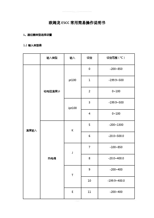
1.1输入类型表
*当输入类型不是铂电阻而错误的将铂电阻接入时,将会显示“5.ERR”。
为了清除“5.ERR”显示,需要正确接线并重新上电。
1.2输入类型修改设置
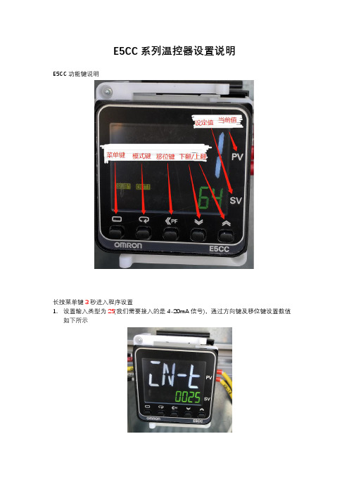
温控器各部名称及功能
长按【菜单键】至少3秒将进入初始设定菜单界面松开,界面右下角显示数字即为当前选择的输入类型,如需修改可按【上调键】或【下调键】来改变,设定完毕后长按【菜单键】直至温控器重启返回。
如:显示数字“5”时,说明当前输入类型为K型热电偶,如需将输入类型改为铂电阻输入,需通过按【上调键】使显示数字变为“0”或“1”或“3”(根据不同测试需要选择设定)。
设定类型表见“1.1输入类型表”。
1.3温控器PID控制设置
长按【菜单键】至少3秒将进入初始设定菜单界面松开,单击【模式键】直至界面显示为“”时,通过单击【上调键】或【下调键】来改变,右下端显示为“PiD”
时即当前模式为“PiD”控制,设定完毕后长按【菜单键】直至温控器重启返回。
1.4防触碰锁设置
长按【菜单键】+【模式键】至少3秒将进入“保护菜单”,通过点击【模式键】切换界面显示至“WEPE”,单击【上调键】或【下调键】使右下角“OFF”变为“ON”,再同时按【菜单键】+【模式键】至少1秒,界面返回至主界面,此时界面会显示“”标志。
如需修改参数,需进行同样操作将“WEPE”变为“OFF”状态。
欧姆龙温度控制器中文手册

欧姆龙温度控制器中文手册1、产品介绍1.1 产品概述欧姆龙温度控制器是一种用于温度调节和监测的设备,能够实时监测目标对象的温度并通过控制输出来调节温度。
1.2 产品特点- 高精度温度监测:欧姆龙温度控制器可以提供高精度的温度监测,确保目标对象的温度得到准确测量。
- 稳定的温度控制:通过控制输出,欧姆龙温度控制器能够实现对目标对象的温度进行稳定控制,确保温度在设定范围内保持稳定。
- 多种控制模式:欧姆龙温度控制器支持多种不同的控制模式,包括PID控制、ON/OFF控制等,以满足不同的应用需求。
- 友好的用户界面:欧姆龙温度控制器具有直观的用户界面,易于操作和设置。
1.3 适用范围欧姆龙温度控制器适用于需要对温度进行调节和监测的各种应用场景,包括工业生产、实验室研究等。
2、产品安装与设置2.1 安装要求在安装欧姆龙温度控制器时,需满足以下要求:- 安装位置应远离高温、湿度、振动和腐蚀性气体等因素。
- 与电源线和信号线的布线应符合相关安全规范。
- 温度探头应与目标对象接触良好,以确保温度测量的准确性。
2.2 设置步骤以下是设置欧姆龙温度控制器的步骤:1.连接电源线和信号线:将电源线和温度探头的信号线分别连接到欧姆龙温度控制器的相应接口上。
2.打开电源:将电源线插入电源插座,并打开电源开关。
3.进入设置模式:按下欧姆龙温度控制器的设置按钮,进入设置模式。
4.设置参数:根据实际需求,设置目标温度、控制模式、控制范围等参数。
5.保存设置:设置完成后,按下保存按钮,保存设置参数。
6.开始控制:按下启动按钮,欧姆龙温度控制器开始工作。
3、产品使用说明3.1 温度调节欧姆龙温度控制器通过调节控制输出来实现对目标对象温度的调节。
根据不同的控制模式,控制输出可以采用不同的方式,比如调节加热器功率或开关状态。
3.2 温度监测欧姆龙温度控制器可以实时监测目标对象的温度,并将温度值显示在用户界面上。
用户可以通过监测结果了解目标对象的温度变化情况。
温控器OMRON E5CWT(中文)

P X J 1 2 3 4 5 6 7
ADJ開關
誤操作
保護開關INIT開關
五、設定注意事項:
(1).亞智出廠設定
ON
P X J 1 2 3 4 5 6 7
(2).若SW1設定為ON時,需搭配“誤操作防止鍵”才可設定。
(3).AL2設定
a.先設定SW4 OFF SW5 ON且警報2設定ON (TC表內部SW)
OMRON E5CWT溫控器操作說明
1、雙警報:
各部名稱
出力動作表示
現在值表示
AT動作表示
警報動作表示
誤操作防止鍵設定值表示
模式切換鍵AT鍵
設定鍵(下)設定鍵(上)
二、配線圖:
2、
(℃)
2
(℃)
依實際
(℃)
0
(%)
(分)
0
0
(%)
四、機能切換開關說明:
控制模式警報模式溫度範圍
選擇開關選擇開關選擇開關
b. 不使用時,將設定為0不動作(不警報)。
c. 設定2,為OH超溫之溫度設定。
d. 設定Байду номын сангаас,為未達工作溫度之溫度設定。
e.上述的b、c、d設定好時,把電源切掉,把TC錶拔出,SW4設回ON,SW5設回OFF,且警報2設回OFF。
E5CC温控器设置说明
E5CC系列温控器设置说明
E5CC功能键说明
长按菜单键3秒进入程序设置
1.设置输入类型为25(我们需要接入的是4-20mA信号),通过方向键及移位键设置数值
如下所示
输入类型对应表
2.输入4-20mA对应温度值-40—120℃设定
按模式键进入如下(CN-H 设置为250CN-L 设置为-40 )
3.设定温度(SL-H设定为100℃,SL-L设定为63℃)
4.控制模式为ONOF,如下
5.选择标准模式STND,如下
6.反向运行(加热)设为OR-R,如下
7.使用报警1,报警类型设置为3 (需求高于67℃停止加热,低于63℃开始加热),如下
报警类型对应输出功能表
8.报警1滞后设置值为1.5,如下
设置完成,按菜单键至少1秒退出。
欧姆龙E5AZ、E5EZ温控表手册、说明书及应用

III
安全使用要求
请确保遵守以下注意事项以保证安全使用。 (1) (2) (3) 为了正确接线,请确认端子极性。不使用的端子,请勿连接。 为避免感应噪音, 温控器接线应远离高压线或大电流的电源电缆并避免与电力线平行或作同一配线。 推荐使用独立 的管道、导管或带护套的屏蔽。 请勿在下列环境中使用 有粉尘或腐蚀性气体(尤其是硫化气体、氨气等)存在的地方。 会产生结冰、凝露的地方。 阳光直射的地方 受到振动或冲击剧烈的地方 水、油等飞溅的地方 受加热器直接辐射的地方 温度变化剧烈的地方 (4) (5) 为便于散热,温控器周边请勿封闭。 (确保留有足够的空间散热。 ) 请勿堵塞温控器外壳上的通风孔。 在各型号规定的温度和温度范围内使用和储藏温控器, 当二个或多个温控器水平紧靠安装或垂直紧安装时, 由于温 控器的热辐射会导致内部温度上升而降低使用寿命。 这种情况下, 需要采取风扇强制冷却或其它通风措施来降低温 控器的温度,但是,小心不要单冷却接线端部分以避免造成测量误差。 (6) (7) (8) (9) (10) (11) (12) (13) (14) 当从盒体内取出或向盒体放置内部装置或连线装置时,请勿触碰到内部电气元件,或撞击内部装置。 清洗时,请勿使用油漆稀释剂或类似产品。请使用标准等级的酒精。 使用规定尺寸 (M3.5, 宽不大于 7.2mm) 的波纹端子接线。 连接线采用 AWG24~AWG14 规格线材, 剥线长度 5~6mm。 尽量将 E5AZ/E5EZ 温度控制器和产生强高频 (如高频焊接、高频缝纫机)噪声或电涌的装置分开配置。 执行自调节时,在导通主体单元的同时或之前导通负载(如加热器) 。如果在导通负载前将主体单元导通,将可能 无法获得正确的自调节结果和实现最佳控制。 使用符合 E5AZ/E5EZ 电源规格的电源,即 100-240VAC(50/60Hz)。同时确保电源接通后 2 秒内电压达到额定值。 在会产生噪音的外围设备(特别是马达、变压器、螺线管、磁线圈或其它带有电感元件的设备)上安装电涌抑制器 或噪声滤波器。 给电源安装滤波器时,确保滤波器有足够的电压和电流容量,尽量将滤波器安装在离 E5AZ/E5EZ 温度控制器最近 的地方。 请在以下温度和湿度范围内使用温控器: 温度:-10℃~55℃(无结冰或凝露现象) ,相对湿度:25%~85%(RH) 。 如把 E5AZ/E5EZ 安装在控制面板内,确保温控器周围(不是控制面板周围)的温度不超过 55℃。 如果 E5AZ/E5EZ 温度控制器受到热辐射,应使用风扇将 E5AZ/E5EZ 温度控制器的表面温度降至 55℃以下。 (15) (16) (17) (18) (19) (20) (21) 请在以下温度和湿度范围内存放温控器: 温度:-25℃~65℃(无结冰或凝露现象) ,相对湿度:25%~85%(RH) 。 请勿将重物放在 E5AZ/E5EZ 温度控制器上,或对其施加压力,以防止产品使用或保存中变形或毁坏。 请勿在靠近收音机、电视机或无线装置的位置使用 E5AZ/E5EZ 温度控制器,这些装置可能会对本产品造成干扰, 影响其性能。 对 E5AZ/E5EZ 预热 30 分钟以上。 电源启动后经约 4 秒钟输出才开启,在配置控制回路时请给予充分的考虑。 在向初始菜单切换后,控制输出关闭。请在组态时给予考虑。 安装一个开关或断路器,并明显标记出其位置,以便操作者能迅速关闭 E5AZ/E5EZ 温度控制器。
OMRON温控仪参数设定方法

OMRON温控仪参数设定方法步骤一:了解OMRON温控仪的基本菜单1.“设置”选项:用于设定基本参数和通信设置。
2.“输入”选项:用于设定输入信号类型和测量范围。
3.“输出”选项:用于设定输出信号类型和控制模式。
4.“报警”选项:用于设定报警方式和阈值。
步骤二:设定基本参数在“设置”菜单中,您可以设定一些基本参数,如时间、日期、单位和显示方式等。
这些参数对于正确的温度控制非常重要。
确保您根据您的应用需求正确设定这些参数。
步骤三:设定输入参数在“输入”菜单中,您可以设定温度传感器类型和测量范围。
确保您选择适合您应用的传感器类型,并根据测量物体的温度范围设置测量范围。
如需设定多个输入信号,请重复此步骤。
步骤四:设定输出参数在“输出”菜单中,您可以设定输出信号类型和控制模式。
根据您的设备和应用要求,选择适合的输出信号类型(如电压、电流或继电器)和控制模式(如PID、ON/OFF或时间比例控制)。
确保正确设定输出参数以实现准确的温度控制。
步骤五:设定报警参数在“报警”菜单中,您可以设定报警方式和阈值。
您可以选择报警器类型(如声音或光指示)和报警阈值(如高温或低温)。
确保您根据应用需求适当设定报警参数以确保及时发现温度异常情况。
步骤六:保存和应用参数设定在完成所有参数设定后,确保您保存设置以保证以后能正确应用这些参数。
通常,您可以在“设置”菜单中找到“保存”或“应用”选项。
选择该选项以将参数设定保存到设备中。
步骤七:验证和调整参数设定在正式应用参数设定之前,建议您验证设置的正确性。
将温控仪连接到目标系统并获取实时温度数据。
验证您设置的传感器、控制模式、输出类型和报警参数是否能正确工作。
如果发现问题,您可以返回相应的菜单选项进行调整。
步骤八:常规维护和调整总结:OMRON温控仪具有广泛应用的智能温度控制设备。
通过了解设备的基本菜单选项,正确设定基本参数、输入参数、输出参数和报警参数,您可以实现准确、稳定的温度控制。
++温控器E5CZ和E5CC参数设置

温控器E5CZ和E5CC参数设置选项参数备注长按3s 以上 ①在正常工作界面按一次,进入保护菜单0 按循环列表长按3s 以上 保存并自动退出保护菜单返回到正常工作界面 以上部分,型号E5CZ 是不用设置的,E5CZ 直接从下面部分开始 长按3s 以上 ②在正常工作界面按一次,进入初始设定菜单6 按循环列表C100 加热上限值,根据应用不同设定值不同,喷嘴加热块通常设置为100,轨道加热块设置为250-20PIDOFF610.20.2以下两项,型号E5CZ是没有的,E5CC要设置下面两项才能打开报警输出1 -169输入-169自动转到高级设定,按切换到ALM1改为ALM1后,上面才会出现上面的长按一次退回初始设定菜单,再短按一次进入通信设定菜单Mod 按循环列表数字1.2.3.……1对应流道加热、2对应喷嘴加热、3、4、5、6对应加热列表按顺序的其它加热选项9.6NONE20短按一次返回到初始设定菜单,再长按3s保存并自动退出到正常工作界面③在正常工作界面按一次,切换应用设置菜单0.0 按循环列表0.0STOP 这个是温控器开关,如果上位机不能控制或没有上位机(C-180),可以作为手动开关来控制加热3.03.0④在正常工作界面按一次,进入调整菜单E5CCOFF按循环列表,在这个列表,型号E5CC 有很多项是没有的 ON 0.0 这三项有变成0.1的,可忽略不管 0.0 0.0 50.0 0.0 31.4 28 10 OFF 105.0 -5.0 按一次 退出到正常工作界面 补充说明:有很多是默认值不用改的,遇到没有的选项直接跳过。
- 1、下载文档前请自行甄别文档内容的完整性,平台不提供额外的编辑、内容补充、找答案等附加服务。
- 2、"仅部分预览"的文档,不可在线预览部分如存在完整性等问题,可反馈申请退款(可完整预览的文档不适用该条件!)。
- 3、如文档侵犯您的权益,请联系客服反馈,我们会尽快为您处理(人工客服工作时间:9:00-18:30)。
欧姆龙温控表e5ec参数说明书
欧姆龙温控表E5EC是一种数字温度控制器,用于监测和控制温度。
以下是对E5EC参数的详细说明:
1. 输入信号类型,E5EC可以接受多种类型的输入信号,包括
热电偶、热敏电阻、电流和电压等。
这使得它适用于不同类型的温
度传感器。
2. 控制方式,E5EC具有多种控制模式,包括比例控制(P控制)、比例积分控制(PI控制)和比例积分微分控制(PID控制)。
这些控制方式可以根据具体应用的需要进行选择。
3. 输出方式,E5EC可以通过继电器输出或模拟电流输出来控
制外部设备。
继电器输出适用于需要开关控制的设备,而模拟电流
输出则适用于需要连续调节的设备。
4. 温度范围,E5EC可以适应不同的温度范围,具体范围取决
于所选用的温度传感器。
它可以在负数温度到较高温度范围内进行
精确控制。
5. 显示和操作,E5EC配备了液晶显示屏,可以直观地显示当
前的温度和设定值。
通过按键操作,用户可以进行设定参数、选择
控制模式和调整输出等操作。
6. 报警功能,E5EC具有报警功能,当温度超过设定的上下限
值时,它可以触发报警信号,以便及时采取措施。
7. 通信接口,E5EC还提供了通信接口,可以与上位机或其他
控制系统进行通信,实现远程监控和控制。
8. 安全保护,E5EC具有多种安全保护功能,包括输入信号断
线检测、过温保护和电源保护等,以确保设备的稳定运行和安全性。
总结起来,欧姆龙温控表E5EC是一款功能强大的数字温度控制器,具有多种控制模式、输入信号类型和输出方式,适用于各种温
度控制应用。
它具有直观的显示和操作界面,提供了报警功能和通
信接口,同时还具备安全保护功能,确保设备的稳定性和安全性。