中文翻译-从大型数据点自动生成数控刀具路径
UG后处理中英文翻译
AAaxis A轴ACL ASCII刀位文件ACL/BCL Generation ACL/BCL 生成器Action Mode 激活模式Activation Range 自动进刀范围Add Arcs 增加圆弧Add Ranges 增加切削范围Add To List 增加到列表ADDED STOCK 增加的余量Adding a post command 增加一个后置命令Additional Passes 附加轨迹Adjust Active 刀补激活Adjust Region 刀补范围Adjust Register 刀长补寄存器After each Engage 每次进刀之后After Each Pass 每条刀轨之后After each Retract 每次退刀之后After Each Subop 每次子操作之后After Last Motion 最终运动之后All but Faces 除了面的所有类型All but Steep 除了陡壁的所有类型All Loops 所有的环All Passes 所有刀轨Allow Oversize Tool 允许偏大刀具Analysis Tools (刀轨)分析工具Analyze Cut Shapes 分析切削外形Analyze Tool Path 分析刀轨ANGLE 1,ANGLE 2,DISTANCE 角1,角2,距离Angle Tolerance 角度公差ANGLE,ANGLE,PLANE 角度,角度,平面Angle/DS 角度/驱动面Angle/PS 角度/零件面Animate 动态模拟Animate Tool Path 动态模拟刀轨Animation Speed 动态模拟速度Append 附加Appended Text Active 附加的文本激活Appending Objects 附加对象Approach 趋近速度Approach Marker 趋近运动标记Aquamarine 蓝绿色Arc Center Probe 圆心自动定位Arc Output Type 圆弧输出类型Arc:Normal Tool axis 圆弧:垂直刀具轴Arc:Parallel to Cut 圆弧:平行切削方向Arc:Parallel Tool axis 圆弧:平行刀具轴Area Centroid 面积质心Area Milling Drive 区域铣削驱动Area Milling 区域铣削As Final 与最终相同As Initial 与最初相同At Angle to DS 与驱动面成角度At Angle to PS 与零件面成角度Automatic 自动的Auxfun 辅助功能Auxfun Value 辅助功能值Available Functions 有效功能Avoid 避让AVOID CLEARANCE 避让安全平面Avoidance Geometry 避让几何体Away From Line 远离线Away From Point 远离点Axis 轴Axis Off 轴关闭Axis On 轴开启BBackburn 反切口Bad Chains 无效的链接Bad Segments 无效的段Bandwidth 带宽Barrel Cutter 鼓形刀Baxis B轴BCL 二进制文件Before 1st Motion 第一次运动之前Before each Engage 每次进刀之前Before each Retract 每次退刀之前Blank Boundary 毛坯边界Blank Distance 毛坯距离Blank Geometry 毛坯几何体Blank Shape 毛坯外形Blank Stock 毛坯余量Blank 毛坯Blind Hole 盲孔Blue 蓝色Boring Radius 切削刃到车刀轴距离Bottom Regions 底部区域Bottom Surface 底部曲面Boundary Approximation 边界近似Boundary Drive Method 边界驱动方法Boundary Face 边界面Boundary Name 边界名Boundary Type 边界类型Boundary 边界Break Chip 断削钻Break_corner 打断拐角Brown 褐色By Name 通过名称(过滤)By Tool 通过刀具(过滤)CCAM customization CAM客户化CAM Object CAM 对象CAM Setup CAM设置CAM Undo Mark CAM撤消标记Case 情形Catalog Number 目录号Cavity Mill 型腔铣Caxis C轴CCLW 逆时针Center 中心Chain 链接Check 检查Check Boundary 检查边界Check Geometry 检查几何体Check Shape 检查外形Check Stock 检查余量Chip Removal 切屑去除(方法)Chord tolerance 弦公差Circular Feedrate Compensation 圆弧进给速度补偿Circular-Perp to TA 圆弧所在平面垂直于刀具轴 (圆弧格式输出)Circular-Perp/par to TA 圆弧所在平面垂直或平行于刀具轴(圆弧格式输出) Clamp 夹紧Clamp Axis 锁紧轴Clamp Status 锁紧状态Class Selection 分类选择Cleanup Geometry 清理几何体Cleanup Output 清理(几何体)输出Cleanup Output Control 清理(几何体)输出控制Clearance 安全距离Clearance Geometry 安全几何体Clearance Plane 安全平面CLEARANCE PLANE,DISTANCE 安全平面,距离Climb Cut 顺铣Closed 封闭CLSF Actions 刀具位置源文件功能CLSF Manager 刀具位置源文件管理器CLSF Name 刀具位置源文件名CLSF(Cutter Location Source File) 刀具位置源文件CLW 顺时针CNC (Computerized Numerical Control) 计算机数字控制Collect Instances 搜集阵列Collision 碰撞Collision check 碰撞检查Commentary 注释Concave Corner 凹角Concentric Arcs 同心圆弧Configuration File 配置文件Configuration 配置Connection Method 连接方法Consistency Check 连续检查Constant 常量Construct Point 构造点Cont. Path 连续轨迹Contact (Tool Position)接触(刀具位置)Contact Boundary 接触边界CONTACT DIRECTION 接触方向CONTACT DISTANCE 接触距离Continuous Path Motion 连续刀轨运动Control Points (进刀)控制点Conventional Cut 逆铣Convex Corner 凸角Coolant Off 冷却液关Coolant On 冷却液开Coordinate 坐标Corner and Feed Rate Control 拐角和进给速度控制Corner Angle 拐角角度Corner Control 拐角控制Corner Control Angles 拐角控制角Corner Loop Radius 拐弯半径Corner Radius 拐角半径Corner Type 拐角类型Create Next Boundary 创建下一边界Cs Becomes Ds 检查面作为驱动面Cs Becomes Ps 检查面作为零件面Current Level 当前(切削)层Current Range 当前范围Curve Drive Method 曲线驱动方法Curve,Directrix 曲线,准线Curve/Point 曲线/点(驱动)Custom Boundary 自定义边界参数Custom Member Data 自定义(边界)元素数据CUSTOM SURFACE 自定义曲面CUSTOM TOOL AXIS 自定义刀具轴Customize Dialog 客户化对话框Customizing 客户化Cut Angle 切削角Cut Area 切削区域Cut Depth 切削深度Cut Feed Unit 切削速度单位Cut Feedrate 切削速度Cut Level 切削层Cut Method 切削方法Cut Order 切削顺序Cut Region 切削区域Cut Region Display 切削区域显示Cut Region Start Point 切削区域起始点Cut Step 切削步长Cut Type 切削类型Cut 切削CUTCOM 刀直径补CUTCOM Parameters 刀直径补参数Cutcom Register 刀直径补寄存器Cutfeed type 切削速度类型Cutoff 切断Cutoff Status 切断状态Cutoff Stock 切断余量Cutter Compensation 刀具补偿Cutter Diameter Compensation 刀具直径补偿Cutter Length Compensation 刀具长度补偿Cutting 切削(参数)Cutting Move 切削运动Cutting Parameters 切削参数Cyan 青色Cycle Definition Events 固定循环定义事件Cycle Events 固定循环事件Cycle Move Events 固定循环运动事件Cycle Parameter 固定循环参数Cycle Parameter Set 固定循环参数组Cycle 固定循环DDark Red 暗红Dashed Center 刀轨虚线(显示)Data All Chains 所有数据链接Data Current Chain 当前数据链接Default 缺省Defined Functions 定义的功能Definition File Elements 定义文件要素Definition File 定义文件Delay 延迟Departure (刀具)离开Depth First 深度优先Depth Offset 深度偏置Depth Per Cut 每刀切削深度Description 描述Deselect All Members 取消选择所有元素Deselect Last Member 取消选择最后元素Destination point 目标点Diameter 直径Direction 方向Direction Vector 方向矢量Directional Steep 加工陡峭面Directrix 准线Display 显示DISPLAY ARC AND SHEET HOLE 显示圆弧和片体孔Display Cut Direction 显示切削方向Display Drive Path 显示驱动轨迹Display Options 显示选项DISPLAY,REVERSE 显示,反向DISPLAY/VERIFY 显示/验证DISTANCE 距离Downward 向下Draft Angle 拔模角度DRILL 钻削Drilling Geometry 钻削几何体Drilling Tool 钻头Drive Boundary 驱动边界Drive Curve Lathe 驱动曲线车削Drive Geometry 驱动几何体Drive Method 驱动方法DRIVE SURFACE 驱动面DS LOOP PARAMETERS 驱动面循环参数Dual 4-Axis on Drive 双四轴于驱动面上Dual 4-Axis on Part 双四轴于零件面上Dumb Objects 非关联对象Dwell 暂停Dwell Time 暂停时间Dynamic Material Removal 动态材料去除EEdit Display 编辑显示Edit Postprocessing 编辑后置处理Edit Status 编辑状态Editing a post command 编辑一个后置命令End first % 最初结束百分比End last % 最后结束百分比End Operation 结束操作End Point 端点End-Of-Path 刀轨结束End-of-Path Commands 刀轨结束命令END-OF-TOOL-PA TH 刀轨结束Engage /Retract 进刀/退刀方法ENGAGE ANGLE/ANGLE/DISTANCE 进刀角度/角度/距离ENGAGE ANGLES 进刀角度Engage Motion 进刀运动ENGAGE POINT 进刀点ENGAGE TOOL AXIS 进刀刀具轴ENGAGE VECTOR 进刀矢量Engage 进刀Entity Subtype 实体子类型Entity Type 实体类型Entrance Diameter 沉孔直径Environment 环境Event 事件Event Generator 事件生成器Event Handler 事件处理器Excess Material 剩余材料Exclude Face 排除的面Expand 扩张Ext.Tan 相切延伸Extend 延伸Extend at Convex Corner 在凸角处延伸Extend open boundary 延伸开口边界Exterior Edges 外部边缘FFace Geometry 面几何体Faces & Curves 面和曲线Facing 面铣Fan 扇形Far Side 远侧Feed per Tooth 每齿进给量Feed Rate Output Mode 速度输出模式Feed Unit 速度单位Feedrate 进给速度Feeds and Speeds 进给速度和面速度Fillet Radius 圆角半径Filter Methods 过滤方法Final 最终Final Event 最终事件Final Retract 最终退刀FINAL STOCK 最终余量Finish Cutting 精加工Finish Only 只精加工Finish Pass 精加工刀轨Finish Stock 精加工余量Finished Preview 结束预览First Cut 首刀(进给量)First Cut/Last Cut 第一刀轨迹/最后一刀轨迹Fixed Contour 固定轴曲面轮廓铣Fixed Depth 固定深度FIXED POINT 固定点Fixed Tool 固定的刀具Fixed Tool Axis 固定的刀具轴Fixture 夹具Fixture Offset 夹具偏置(号)Fl Stck/Min Clr 零件底面余量/最小安全距离Flip Material 材料反向Flip Material Side 材料侧反向Flood 流水状(冷却液形式)Floor 底面Floor & Island Tops 切削底平面和各岛屿的顶面Floor Only 只切削底平面Floor Plane 底平面Floor Same As Side 底面和侧壁(余量)一致Flow Cut - Cut 清根切削 -切削Flow Cut - Cut Method 清根切削-切削方法Flow Cut - Hookup Distance 清根切削-连接距离Flow Cut - Manual Assembly 清根切削-手工组合Flow Cut - Max concavity 清根切削-最大凹度Flow Cut - Min Cut Length 清根切削-最小切削长度Flow Cut - Number of offsets 清根切削-刀轨偏置条数Flow Cut - Offset Mode 清根切削-刀轨偏置模式Flow Cut - Output Type 清根切削-输出形式Flow Cut - Overlap 清根切削-重叠距离Flow Cut - Reference 清根切削-参考刀具(直径)Flow Cut - Sequencing 清根切削-刀轨顺序Flow Cut - Stepover 清根切削-步距Flow Cut 清根切削Flute Length 刀刃长度Follow Boundary 沿着边界方向Follow Check Geometry 沿着检查几何体Follow Part 仿形零件Follow Periphery 仿形外轮廓Follow Pocket 仿形内腔Follow Predrill Points 沿着预钻孔点Follow Start Points 沿着起始点Format 格式FORWARD 向前FPM/FPR 每分钟…英尺/每转…英尺Frequency 频率FROM A POINT 起始于一点From Marker 从点标记From 从点Full Cutcom Output 完全刀补输出Full Feed Rates 完全进给速度GGenerate 生成Generate ISO CLF 生成ISO刀位轨迹文件Generate STD CLF 生成标准的刀位轨迹文件Generate Tool Path 生成刀位轨迹Generic Plane 通用平面Generic Point 通用点Geometry 几何体Geometry Groups 几何体组Geometry objects 几何体对象Geometry Type 几何体类型Geometry View 几何体视图Gohome 回零点GOTO 转移到Gouge Check Area 过切检查区域Gouge Check 过切检查Gouges Detected 过切探测Graphical Editor 图形编辑器Graphical Postprocessing Module (GPM) 图形后处理模块Gray 灰色Green 绿色GROOVE 槽Grooving Tool 车槽刀Group 组HHead 主轴头Head Designation 主轴头选择Heel Angle 后角Helical 按螺旋线(斜坡进刀)Helical: Climb 螺旋线:顺铣Helical: Conventional 螺旋线:逆铣Highlight 高亮Hin Value 锥度刀从刀尖沿着刀轴的垂直距离Holder Length 装夹台长度Holder Width 装夹台宽度Hookup Distance 连接距离HORIZONTAL CLEARANCE 水平间隙Horizontal Limit 水平限度II direction I方向Ignore Chamfers 忽略倒角Ignore Holes 忽略孔Ignore Islands 忽略岛屿Ignore Loops 忽略环IN ALL TOOL PATHS 在所有刀轨中IN LAST TOOL PATH ONLY 只在最后一条刀轨中Inches 英寸Increment 增量Incremental Side Stock 侧壁余量增量Incremental Stock 余量增量Info 信息Inheritance 继承Initial 初始Initial Engage 初始进刀Initial Event 初始事件INITIAL STOCK 初始余量Initialize 初始化Input File Name 输入文件名Input Units 输入单位Insert 插入Insert Angle 车槽刀角度Insert Width 车槽刀宽度Inside 内部Inside-Out 由内向外Internal Engage 内部进刀Internal Error 内部错误Internal Retract 内部退刀Internal_lift 内部抬刀Interpolate 插补Intol 内公差Invalid CLSF specified 无效的CLSF指定Invalid configuration 无效的配置INVALID END AXIS 结束刀轴无效INVALID END POINT 结束点无效Invalid Feed 无效的速度Invalid setup template 无效的模板设置INVALID START AXIS 起始刀轴无效INVALID START POINT 起始点无效Invalid Tool 无效刀具Invalid Tool Pattern 无效的刀具模式Inward 向里Ipm 每分钟…英寸Ipr 每转…英寸Island Boundary 岛屿边界Island Cleanup 岛屿清理Island 岛屿JJ direction J方向Join Segments 连接段kk direction K方向LLargest Loop 最大环Laser 激光Last Cut 最后一刀(轨迹)Lathe Control 车削控制Lathe Cross-Section 横切面(用于车削) LATHE DRILL 车削钻孔LATHE DRIVE CURVE 车削驱动曲线Lathe Finish 精车Lathe Groove 车槽Lathe Rough 粗车Lathe Thread 车螺纹Layer/Layout 层/视图布局Lead 引导Lead Angle 前角Lead In Point 引入点Lead in/ Lead Out 引入/引出Lead Out Point 引出点LEAD/LAG(DEGREES) 前导角和后导角Left 左侧Left Radius 左半径Length 长度Level First 水平优先Levels At Island Tops 切削各岛屿的顶面Libraries 库Lift at Convex Corner 在凸角处抬刀Lifts 抬刀Line End Points 直线的端点Line Printer 行式打印机Linear 线性的Linear Only 直线格式(输出)Link MCS/RCS 链接加工坐标系/参考坐标系List 列表显示List ACL 列表显示ACLList All Chains 列表显示所有链接List BCL 列表显示BCLList Current Chain 列表显示当前链接List Tool Path 列表显示刀位轨迹Listing Options 列表选项Listing Output 列表输出Local 局部Local Engage/Retract 局部进刀/退刀Local Return 局部退刀Longest Line 最长直线Loop 环LOOP CONTROL 循环控制loop in face 在面中的环Loop Type 环类型Lower Limit Plane 低限平面Lower Plane 最低平面Lower Radius 最小半径LPT 行式打印机文件MMachine Control 加工控制Machine Control Events 机床控制事件Machine Data File Generator (MDFG) 机床数据文件生成器Machine Tool 机床Machine Tool Kinematics 机床运动学Machine Tool Motion Control 机床运动控制Machine Tool Type Options 机床类型选项Machine Tool View 刀具视图Machining Environment 加工环境Machining Method 加工方法Machining Method View 加工方法视图Machining Parameters 加工参数Magenta 洋红色Manufacturing 制造(加工)Manufacturing Output Manager (MOM) 加工输出管理器Material Retained 材料保留侧Material Side 材料侧Max Concavity 最大凹度Max Depth 最大深度Max Stepover 最大步距Max. Corner Angle 最大拐角角度Max. Tool Axis Change 最大刀具轴改变Maximum Diameter 最大直径Maximum Height 最大高度Maximum RPM 每分钟最高转速Maximum RPM Active 每分钟最高转速激活MCS (Machine Coordinate System) 加工坐标系MCS Origin 加工坐标系原点MCS Rotate 加工坐标系旋转MDF (Machine Data File) 机床数据文件MDF Defined 机床数据文件定义MDF Name 机床数据文件名Member 元素,成员Method Groups 方法组Method Objects 方法对象Mid Point 中点Mill 铣削Mill Area 铣削区域Mill Boundary 铣削边界Mill Control 铣削控制MILL DRIVE CURVE 铣削驱动曲线Mill Geometry 铣削几何体Millimeters 毫米Milling Tool 铣刀Min Clearance 最小间隙Min Cut Length 最小切削长度Min Stepover 最小步距Min. Tool Axis Change 最小刀具轴改变Minimum Angle 最小角度Minimum Clearance Distance 最小安全距离Minimum Diameter 最小直径Minimum Move 最小运动距离Missing END-OF-PA TH 缺少轨迹结束语句Mist 薄雾状(冷却液形式)Mmpm 每分钟…毫米Mmpr 每转…毫米Modify Boundary End 修改边界末端Modify Boundary Start 修改边界始端Modify Ranges 修改范围More Drive Parameters 更多驱动参数Motion Output 运动输出格式Move Control 运动控制Move Down 向下运动Move Events 运动事件Move Status 运动状态Move Up 向上运动Movement 运动形式Multi-Depth Cut 多层切削Multiple Offsets 多层偏置NNC (Nunerical Control) 数控NC Output NC输出NC Postprocessing NC后置处理Near Side 近侧Next Boundary 下一边界Next Chain 下一链接NEXT CUT DIRECTION 下一切削方向Next Member 下一成员Next Segment 下一段No APP_BND 无附加的边界No APP_BND_MEMBER 无增加的边界成员No Cycle 无固定循环No Display 无显示No Gouges 无过切NO POINTS TO DISPLAY 没有点显示NO POINTS TO OMIT 没有点可以省略NO POINTS TO OPTIMIZE 没有点可以优化NO POINTS TO REVERSE 没有点可以反向NO TOOL PATHS IN CLSF CLSF中没有刀位轨迹Non Cutting Control 非切削控制Non-cutting Move 非切削运动Non-Steep (加工)非陡峭面Non-steep Face 非陡峭面Normal to Drive 垂直于驱动面Normal to DS 垂直于驱动面Normal to Part 垂直于零件面Normal to PS 垂直于零件面Nose Radius 球头半径Not Specified 没有指定Number of Flutes 切削刃条数(齿数)Number of Offsets 偏置数目Number of Passes 轨迹数目Number of Steps 步长数目Nurbs Motion Nurbs运动Nurbs(Non Uniform Rational B-spline) Nurbs格式输出(非均匀有理B样条) OOff 关闭Offset 偏置Offset/Gouge 刀具偏置/过切检查Olive 橄榄色Omit 忽略On (Tool Position) 在刀具中心位置上On Lines 按直线(斜坡进刀)On Shape 按外形(斜坡进刀)On Surface 在曲面上On Wall 在周壁上ONT (Operation Navigation Tool ) 操作导航工具Open 开口,打开Operation Generation 操作生成器Operation objects 操作对象Operation Transform 操作转换Operation 操作Operator Message 操作者提示Optimize 优化Optimize Path 优化轨迹Optimize Ponits 优化点Optional Skip Off 程序跳段结束Optional Skip On 程序跳段开始Orange 橙色Orient Angle 定向角度Origin 原点Output File 输出文件Output File Validation 输出文件有效Output Plane 输出(插补)平面Output Register Number 输出寄存器号Outside 外部Outside-In 由外向内Outtol 外公差Outward 向外Overlap 重叠Overlap Distance 重叠距离Oversize Tool 偏大刀具PPaint Arrows 描绘箭头Paint Display 描绘显示Paint Feeds 描绘速度Paint Line Numbers 描绘行号Paper Tape 纸带Parallel Lines 平行线Parallel to PS 平行于零件面Parallet to DS 平行于驱动面Parameter Groups 参数组PARAMETER LINE 参数线PARAMETER SET 参数设置Parameters 参数Parent 父节点Part 零件Part Boundary 零件边界Part Containment 零件边界控制Part Floor Stock 零件底部余量Part Geometry 零件几何体Part Intol 零件内公差Part Material 零件材料Part Outol 零件外公差Part Shape 零件外形Part Side & Floor 零件侧边和底面Part Side Stock 零件侧面余量Part Stock 零件余量Part Stock Offset 零件余量偏置Part Surface 零件面PARTNO 零件号Path Display 刀轨显示Pattern 刀夹,切削模式Pattern Center 同心圆模式中心Pattern File Name 刀夹文件名Pattern frequency 刀夹(显示)频率Pause After Display 显示后暂停Pause After Each 每条(刀轨)显示后暂停Peck Drill 啄钻Per Minute 每分钟Per Step 每步长Percent 百分比Percent Tool 刀具直径百分比Perform Gouge 执行过切检查Permanent Boundary 永久边界Pink 粉红色Planar Milling 平面铣Plane Matrix 平面矩阵Plane Origin 平面原点Plane Type 平面类型Plunge 插入Pocket Direction 内腔方向Pocket 内腔Point Angle 顶尖角Point Boundary 点边界Point Coordinates 点坐标Point to Point Motion 点到点运动Point to Point 点位加工POINTS ONL Y,ARCS ONL Y,HOLES 仅点,仅圆弧,孔Post Command Dialog 后置命令对话框Post Commands 后置命令Post Commands At End 刀轨结束后的后置处理命令Post Commands At Start 刀轨开始前的后置处理命令Postprocess 后置处理Postprocess Name 后置处理名Postprocessor 后置处理器Postprocessor Name 后置处理器名Power 功率Pre-Drill Engage Points 预钻孔进刀点Predrill Points 预钻孔点Pre-Drill 预钻孔Preferences 预设置Prefun 准备功能Prefun Value 准备功能值preloaded 预装载Prepare Geometry 准备几何体Preprocess 预处理Preview Region 预览区域Previous 预览Previous Check Surface 先前的检查面Previous Drive Surface 先前的驱动面Previous Part Surface 先前的零件面Previous Tool 前一把刀具Process 过程Process Display 过程显示Profile 轮廓Program Groups 程序组Program objects 程序对象Program Order View 程序顺序视图Program 程序Proj DS Normal 沿驱动面法向投射Proj PS Normal 沿零件面法向投射Projection Vector 投射矢量PS LOOP PARAMETERS 零件面循环参数PTP 后处理过的文本文件Punch 冲床,冲孔Purple 紫色RRadial Cut 射线状切削Radial Cut Drive 射线状切削驱动Radial Lines 射线Ramp Angle 斜坡角度Ramp Down Angle 向下斜坡角度Ramp Type 斜坡进刀类型Ramp Up Angle 向上斜坡角度Ramping 斜坡Range 切削范围Range Bottom 切削范围底部Range Depth 切削范围深度Range Selection 切削范围选择Range Top 切削范围顶部Rapid 快速进给速度Rapto Offset 快进偏置RCS (Reference Coordinate System) 参考坐标系Rebuild Topology 重建拓扑关系Red 红色Redisplay Tool 重新显示刀具Reference 参考Reference Tool Offsets 参考刀具偏置Refresh 刷新Refresh Before Display 显示前刷新Refresh Before Each 每条刀轨显示前刷新Regenerate 重新生成Region Connection 区域连接Region Sequencing 切削区域的顺序Region Type 区域类型Register Number (刀具补偿)寄存器号Reinitialize 重新初始化Reject 拒绝Relative to Drive 相对于驱动面Relative to Part 相对于零件面Relative to Vector 相对于矢量方向Relocate Parameters 重新设置参数Remove Boundary 移去边界Remove Current Range 移去当前切削范围Remove Edge Trace 移去边缘刀轨Remove Last 移去最后的Remove Member 移去成员Renumber 重编号Replace/Add 替换/增加Replay 重新显示Reposition 重定位Reposition Engage/Retract 重定位进刀/退刀Repost 重新后置处理Resequence Regions 重新排列区域顺序Reset 重新设置,复位Reset All 重新设置所有的Reset from Table 从表中重新设置Reset to Default 重新设置为缺省Reset to Original 重新设置为最初的Respecify Tool 重指定刀具Restore Original Csys 恢复原始坐标系Retract Angles 退刀角度Retract Clearance 退刀安全高度Retract Motion 退刀运动Retract plane 退刀平面Retract Point 退刀点Retract Vector 退刀矢量Retract 退刀Retrieve 恢复Retrieve Global 恢复全局Retrieve Tools 恢复刀具Return 刀具返回Reverse All 所有反向Reverse Arc and Sheet Hole 圆弧和片体孔反向Reverse Boundary 边界方向反向Right 右侧Right Radius 右半径Ring Height 环状高度Ring Radius 环状半径Rotate 旋转Rotation Angle Active 旋转角激活Rough & Finish 粗加工和精加工Rough Only 仅粗加工Rough Operation 粗加工操作Rough Pass 粗加工刀轨Rough Pass & Backburn 粗加工刀轨和反切口Rough - To - Depth 粗加工到深度RPM 每分...转RTRCTO 退刀到(距离)SSafe Clearance 安全距离Same As CLS 与CLS相同Same As Drive Path 与驱动刀轨(刀具轴)相同Same Start And End Axis 与开始和结束刀轴矢量相同Same Start and End Point 与开始和结束点相同Sample 样例Save 3D 存贮三维模型Save As Global 存贮为全局Save Current Csys 存贮当前的坐标系Save Failed 存贮失败Save/Restore Csys 存贮/恢复坐标系Scallop Height 残留高度Seed Face 种子面Segment Consistency 段连续SEL END POINT 选择终点SEL START POINT 选择起点Select a Group 选择一个组Select Adjacent Faces 选择相邻面Select chain end 选择链接末端Select chain start 选择链接始端Select Head 选择主轴头Select Holes 选择孔Select Next Row 选择下一行Selection Method 选择方法Self Intersection 自相交Separator Item 分隔符Sequence Number 顺序号Sequencing 顺序Sequential Milling 顺序铣Set Modes 设置模式SET/ADJUST 设置/调整Setup Events 设置事件Setup Template 设置模板Setup 设置SFM 每分钟…英尺(表面线速度)Shape 外形Shop Documentation 车间工艺文档Shortest Path,Horizontal 最短刀轨,水平的Show 3D 显示三维模型Show Excess 显示剩于量Show Gouging 显示过切Side Cut 侧壁切削Side Trimmed 侧壁修剪Silhouette 轮廓Silhouette Display 轮廓显示Simulated 模拟Single 单一Single Pass 单条刀轨Skip 跳过Slowdowns 降速Smart Object Action 相关联对象激活Smart Objects 相关联对象SMM 每分钟…毫米(表面速度)Solid Center 刀轨实线(显示)Specify 指定Specify Boundary 指定边界Specify Boundary Plane 指定边界平面Specify Colors 指定颜色Specify Cut Angle 指定切削角度Specify Pattern 指定刀夹(切削模式)Specify Point 指定点Specify Setup 指定设置Specify Tool Axis 指定刀具轴Speed 转速Spherical Coords 球坐标Spindle Axis 主轴Spindle Off 主轴停止Spindle On 主轴启动Spindle Range Active 主轴转速范围激活Spindle Speed 主轴转速Spindle Speed Active 主轴转速激活Spiral 螺旋线驱动Spiral Center Point 螺旋线中心点Spiral Drive Method 螺旋线驱动方法Split Closed Boundary 断开封闭的边界Standard Bore 标准镗Standard Bore,Back 标准镗,插孔Standard Bore,Drag 标准镗,快退Standard Bore,Manual 标准镗,手工退刀Standard Bore,No Drag 标准镗,横向偏置后快退Standard Drill 标准钻削Standard Drill,Break Chip 标准钻削,断屑Standard Drill,Csink 标准钻削,沉孔Standard Drill,Deep 标准钻削,深孔Standard Drive 标准驱动铣Standard Tap 标准攻螺纹Standard Text 标准文本(输出)Start & End Points 开始和结束点Start first % 最初开始百分比Start last % 最后开始百分比Start Marker 起始点标记Start of range 起始范围Start Point 起始点Start step 起始步长Startup 启动Startup Commands 启动命令Startup Position 启动位置Static Material Removal 静态材料去除Status 状态Steep 陡峭壁Steep Angle 陡峭壁角度Steep Area 陡峭壁区域Steep Faces 陡峭壁面Steep Merge 陡峭壁合并Steep Option 陡峭壁选项Steep Overlap 陡峭壁重叠Steep Part 陡峭壁零件Step Over 步距(进给速度)Step Size 步长大小Step Type/Dir 步距类型/方向Stepover Method 步距方法Stepover Parameters 步距参数Stepover 步距Stock 余量Stock type 余量类型Stock value 余量值Stop Animation 停止动态模拟Stopping Position (刀具)停止位置StptChange 起始点改变Subop to Execute 执行子操作Sub-Operations 子操作Sub-Type 子类型Suppress Tool Path 抑制刀轨Surf Cont 曲面连续Surf. Contour 曲面轮廓Surface Area Drive 曲面区域驱动Surface Drive Method 曲面驱动方法Surface Inside Tolerance 曲面内公差Surface Outside Tolerance 曲面外公差Surface Percentage Method 曲面百分比方法Surface Region Editing 曲面区域编辑Surface Region 曲面区域(特征)Surface Speed 表面切削速度Surface Stock 曲面余量Swarf Drive 直纹面驱动TTable 工作台Tangent to Curve 相切于曲线Tangent to DS 相切于驱动面Tangent to PS 相切于零件面Tangential Edge Angle 相切边角度Tanto (Tool Position) 相切(刀具位置)Tap 攻螺纹Taper Angle 锥度角T-Cutter T形刀Template Set 模板设置Template units 模板单位Templates 模板Temporary Boundary 临时边界Temproary Plane 临时平面The Event Generator 事件生成器The Event Handler 事件处理器Thick 厚,粗Thin 薄,细THREAD 螺纹Thread Milling 螺纹铣Threading Tool 螺纹车刀Three Point Probe 三点(圆心)探测Thru Fixed Pt 通过固定点Thru Hole 通孔Thru point 通过点Tilt 倾角Tip Angle 顶尖角TMARK 程序转移标识Tolerances 公差Tolerances – Intol/Outtol 内公差/外公差Tolerant Machining 容错加工Tool Axis Output 刀具轴输出Tool Axis 刀具轴(刀轴)Tool Axis/Distance 刀具轴/距离Tool Change 换刀Tool Checker 刀具检测器Tool Diameter 刀具直径Tool Display 刀具显示Tool Groups 刀具组Tool Holder 刀柄Tool Material 刀具材料Tool Number 刀号Tool Objects 刀具对象Tool Path Actions 刀轨功能Tool Path Options 刀轨选项Tool path Reversed 刀轨反向Tool Path 刀位轨迹(刀轨)Tool Position 刀具位置Tool Preselect 刀具预选Tool Radius 刀具半径Tool 刀具toolpath_generate 刀轨-生成toolpath_list 刀轨-列表toolpath_reject 刀轨-拒绝toolpath_replay 刀轨-重新显示toolpath_verify 刀轨-验证Top Level 顶部切削层Topology 拓扑Total Depth 总深度Toward Line 指向线Toward point 指向点Trace (刀轨)迹线Transfer Method 转移方法Traversal 横过Traverse Interior Edge 横过内边缘Traverse Pattern 横过模式Triangle Tolerance 三角形公差Trim 修剪Trim Boundary 修剪边界Trim Curve 修剪曲线Trim Geometry 修剪几何体Trim Intol 修剪内公差Trim open boundary 修剪开口边界Trim Outtol 修剪外公差Trim Shape 修剪外形Trim Tool Paths 修剪刀轨Turn 车床Turning Tool 车刀Turning 车削Type 类型UUGPOST UG后置处理器Uncut Region Display 未切削区域显示Uncut Regions 未切削区域Undefined 未定义Undercut Handing 底部切削处理Unidirection 单一方向Unify All 统一所有的材料侧Unlink Instances 取消所有引用特征的链接Update All Instances 更新所有的引用特征Updating Surface 更新曲面Upper Plane 上平面Upward 向上Use Check 使用检查功能Use Final 使用最后退刀Use Initial 使用初始进刀Use Local 使用局部的进退刀Use Reposition 使用重新定位Use Tool Holder 使用刀柄Use Vericut Display 使用V ericut模拟切削显示User Abort 用户中断User Defined 用户定义User Defined Command 用户定义命令User Defined Event (UDE) 用户定义事件VValley Merge 凹处合并Valley Overlap 凹处重叠距离Valleys 凹处Variable 可变的Variable Contour 可变轴曲面轮廓铣Variable Increments 可变增量Vericut Display 模拟切削显示Vericut 模拟切削Verify 验证Verify or modify check surface 验证或修改检查面Verify Points 验证点Verify Predrill Points 验证预钻孔点Vertex Type 顶点类型Vertical Clearance 垂直间隙Vertical Limit 垂直限制Visualize 可视化切削仿真WWall Cleanup 周壁清理Warning 警告WCS Origin WCS原点WEDM Control 线切割控制When Gouging 当过切时White 白色Wire EDM 线切割Wire-EDM Feature 线切割特征Workpiece 工件XX Center R1 R1中心至刀轴X向距离X Center R2 R2中心至刀轴X向距离X Delta X向增量X Offset X向偏置Xaxis X轴YY Center R1 R1中心至刀轴Y向距离Y Center R2 R1中心至刀轴Y向距离Y Delta Y向增量Y/Z Offset Y/Z向偏置Yaxis Y轴Yellow 黄色ZZ Delta Z向增量Z Offset Z向偏置Zaxis Z轴Z-Depth Offset Z向深度偏置Zero 参考零点Zig with Contour 单向带轮廓铣Zig with Stepover 单向带步距铣Zig 单向切削Zig_Zag Surface 往复式曲面铣Zig-Zag with Lifts 往复式切削带抬刀Zig-Zag 往复式切削Z-Level Milling 等高轮廓铣。
数控机床刀具设计论文中英文资料外文翻译文献综述
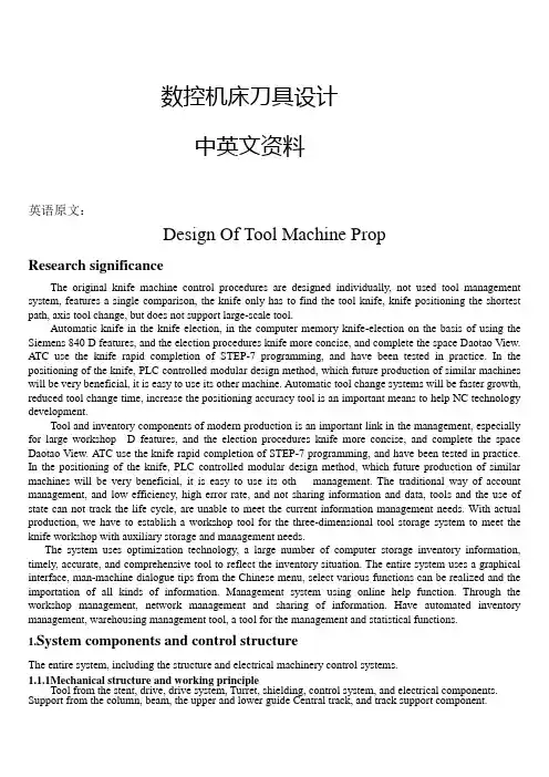
数控机床刀具设计中英文资料英语原文:Design Of Tool Machine PropResearch significanceThe original knife machine control procedures are designed individually, not used tool management system, features a single comparison, the knife only has to find the tool knife, knife positioning the shortest path, axis tool change, but does not support large-scale tool.Automatic knife in the knife election, in the computer memory knife-election on the basis of using the Siemens 840 D features, and the election procedures knife more concise, and complete the space Daotao View. ATC use the knife rapid completion of STEP-7 programming, and have been tested in practice. In the positioning of the knife, PLC controlled modular design method, which future production of similar machines will be very beneficial, it is easy to use its other machine. Automatic tool change systems will be faster growth, reduced tool change time, increase the positioning accuracy tool is an important means to help NC technology development.Tool and inventory components of modern production is an important link in the management, especially for large workshop D features, and the election procedures knife more concise, and complete the space Daotao View. ATC use the knife rapid completion of STEP-7 programming, and have been tested in practice. In the positioning of the knife, PLC controlled modular design method, which future production of similar machines will be very beneficial, it is easy to use its oth management. The traditional way of account management, and low efficiency, high error rate, and not sharing information and data, tools and the use of state can not track the life cycle, are unable to meet the current information management needs. With actual production, we have to establish a workshop tool for the three-dimensional tool storage system to meet the knife workshop with auxiliary storage and management needs.The system uses optimization technology, a large number of computer storage inventory information, timely, accurate, and comprehensive tool to reflect the inventory situation. The entire system uses a graphical interface, man-machine dialogue tips from the Chinese menu, select various functions can be realized and the importation of all kinds of information. Management system using online help function. Through the workshop management, network management and sharing of information. Have automated inventory management, warehousing management tool, a tool for the management and statistical functions.1.System components and control structureThe entire system, including the structure and electrical machinery control systems.1.1.1Mechanical structure and working principleTool from the stent, drive, drive system, Turret, shielding, control system, and electrical components. Support from the column, beam, the upper and lower guide Central track, and track support component.1) Drive for the system chosen VVVF method. Cone used brake motors, with VVVF by Cycloid reducer through sprocket drive.2) Drag a variable frequency drive system and control technology. VVVF adopted, will speed drive shaft in the normal range adjustment to control the speed rotary turret to 5 ~ 30mm in, the drive shaft into two, two under through sprocket, the two profiled rollers Chain driven rotating shelves. Expansion chain adopted by the thread tight regulation swelling, swelling the regular way. - Conditi D features, and the election procedures knife more concise, and complete the space Daotao View. ATC use the knife rapid completion of STEP-7 programming, and have been tested in practice. In the positioning of the knife, PLC controlled modular design method, which future production of similar machines will be very beneficial, it is easy to use its at six other Des V oeux a knife, can be categorized with some of knife auxiliary equipment, such as bits, such as turning tools.1.1.2.Electrical Control SystemThis tool storage systems is the main electrical control their shelves for operational control and position control. Operational control equipment, including operation of the start of braking control. Position Control is the main location and address of the shelves for testing.1) Electric Transmission horizontal rotary tool storage systems are the mechanical movements are repeated short-term work system. And the run-time system needs some speed, speed transmission needs, the system will use VVVF method can be used simple structure, reliable operation of the motor and frequency inverter.2) Control of the system is divided into two kinds of manual control and automatic control, manual control as a general reserve and debugging methods of work; ways to the system control computer (IPC) and the control unit (inverter contactor , etc.) consisting of a control system.3) location and positioning accuracy of the system automatically identify the site and location using a detection device tion, timely, accurate, and comprehensive tool to reflect the inventory situation. The entire system uses a graphical interface, man-machine dialogue tips from the Chinese menu, select various functions can be realized and the importation of all kinds of information. Management system using online help function. Through the workshop management, network management and sharing of information. Have automated inventory management, warehousing management tool, a tool for the management and statistical fu as proximity switches, relays through the plate-point isolation and the number plate recorded close to the switching signal acquisition and operation of Hutchison with a Optimal Path addressable identify the current location and shelves of the purpose of the shelf location. In order to enable a more accurate positioning system, adopted two photoelectric switches, to detect the two shelves of the two films.1.2.The functions of the knifeknife The is the role of reserves a certain number of tools, machine tool spindle in hand to achieve the fungibility a disc sc knife in the library with discoid knife, cutting tool along See how vertical arrangement (including radial and axial from knife from knife), along See how radial array into acute or arranged in the form of the knife. Simple, compact, more applications, but are ring-cutter, low utilization of space. Figure 2.7 a) to c). D features, and the election procedures knife more concise, and complete the space Daotao View. ATC use the knife rapid completion of STEP-7 programming, and have been tested in practice. In the positioning of the knife, PLC controlled modular design method, which future production of similar machines will be very beneficial, it is easy to use its. If the knife cutter knife is the type of library, the chain knives, and other means, in the form of the knifeand capacity according to the Machine Tool to determine the scope of the process.s, but are ring-cutter, low utilization of space. Figure 2.7 a) to c). D features, and the election procedures knife more concise, and com mon typesThe knife is a tool storage devices, the common knife mainly in the following forms:(1) the turret knifeIncluding the first level turret vertical turret and the first two, see Figure 2.6 a) and b):(2) the disc cutterDisc knife in the library with discoid knife, cutting tool along See how vertical arrangement (includingradial and axial from knife from knife), along See how radial array into acute or arranged in the form of theknife. Simple, compact, more applications, but are ring-cutter, low utilization of space. Figure 2.7 a) to c).D features, and the election procedures knife more concise, and complete the space Daotao View. ATC use theknife rapid completion of STEP-7 programming, and have been tested in practice. In the positioning of theknife, PLC controlled modular design method, which future production of similar machines will be verybeneficial, it is easy to use its. If the knife storage capacity must be increased to increase the diameter of theknife, then the moment of inertia also increased correspondingly, the election campaign long knife. Toolnumber not more than 32 general. Cutter was multi-loop order of the space utilization knife, but inevitablygiven the knife from complex institutions, applicable to the restricted space Machine Tool storage capacity andmore occasions. Two-disc structure is two smaller capacity knife on both sides of the sub-spindle place, morecompact layout, the number ofapply to small and medium-sizedprocessing center.(3) the chain knife Includingsingle-and multi-ring chain ringchain, chain link can take many forms change, see Figure 2.8 a) to c), the basic structure shown in Figure 2. 8 doFeatures: knife apply to the larger capacity of the occasion, the space of the small number of generally applicable to the tool in the 30-120. Only increase the length of the chain tool will increase the number should not be increased circumferential speed of its moment of inertia of the knife does not increase the disc as large.(4) linear combination knife and the knife libraryThe linear knife simple structure in Figure 2.9, tool single order, the capacity of small knife, used for CNC lathe and drill press on. Because the location of fixed knife, ATC completed action by the spindle without manipulator. The cutter knife is generally the turret combination turret with a combination of the disc cutter knife and the chain combination. Every single knife the knife certificates of smaller, faster tool change. There are also some intensive drum wheel, and the lattice-type magazine for the knife, the knife-intensive though.Small footprint, but because of structural constraints, basically not used for single processing center, the concentration used for FMS for the knife system.1.4 Tool storage capacityTool storage capacity of the first to consider the needs of processing, from the use of point of view,generally 10 to 40 knives, knife will be the utilization of the high, and the structure is compact.1.5 Tool options(1) choose to order processing tool according to the order, followed Add to the knife every knife in the Block. Each tool change, the order of rotation of a cutter knife on location, and remove the need knives, has been used by the cutter knife can be returned to the original Block, can also order Add Block, a knife. However, as the knife in the tool in different processes can not be repeated use of the knife must increase the capacity and lower utilization rate.(2) most of the arbitrary choice of the current system of using arbitrary NC election knives, divided into Daotao coding, coding and memory-cutter, three. Daotao coding tool code or knives or Daotao need to install the code used to identify, in accordance with the general principle of binary coding coding. Tool knife election coding method uses a special knife handle structure, and each of the coding tool. Each of the tool has its own code, thereby cutting tool can be in different processes repeatedly used, not to replace the tool back at the original knife, the knife capacity can be reduced accordingly. Memory-election this paper knife, in this way can knives and knife in the position corresponding to the Daotao memory of the PLC in the NC system, no matter which tool on the Inner knife, tool information is always there in mind, PLC . On the knife with position detection devices, will be the location of each Daotao. This tool can be removed and sent back to arbitrary. On the knife is also a mechanical origin, every election, the nearest knife selection.1.6.Control of the knife(1) the knife as a system to control the positioning axis. In the ladder diagram in accordance with the instructions for computing T code comparison of the output angle and speed of instructions to the knife the knife servo drive servo motor. Tool storage capacity, rotation speed, and / deceleration time, and other system parameters can be set in such a manner free from any outside influence positioning accurate and reliable but the cost is higher.(2) knife from the hydraulic motor drives, fast / slow the points, with proximity switches count and positioning. In comparison ladder diagram of the current storage system knife (knife spindle) and goals knife (pre-knife) and computing, then output rotation instructions, judging by the shortest path rotation in place. This approach requires sufficient hydraulic power and electromagnetic valve knife the rotational speed can be adjusted through the throttle. But over time may be oily hydraulic, oil temperature and environmental factors impact the change in velocity and accuracy. Not generally used in large and medium-sized machine tool change frequently.(3) the knife from AC asynchronous motor driven cam mechanism (Markov institutions), with proximity switches count, which means stable operation, and generally accurate and reliable positioning cam used in conjunction with a mechanical hand, ATC fast-positioning.2. ATC, the main types, characteristics, and the scope of application2.1 Auto Rotary ToolRotary Tool automatically on the use of CNC machine tool is a simpleinstallation of automatic tool change, the Quartet and 47.60 Turret Tool various forms, such as rotary turret were installed on four, six or more of the Tool , NCinstructions by ATC. Rotary Tool has two vertical and horizontal, relatively simple structure, applicable to economic CNC lathe.Rotary Tool in the structure must have good strength and stiffness, resistance to bear rough Cutting Tool in the cutting force and reduce the role of deformation and improve processing accuracy. Rotating Tool to choose reliable positioning programme structure and reasonable position, in order to ensure that each rotary turret to a higher position after repeated positioning accuracy (typically 0.001 to 0.005mm). Figure 2.1 shows the spiral movements of the Quartet Turret.Auto Rotary Tool in the simplest of ATC, is 180 º rotary ATC devices, as shown in Figure 2.2 ATC instructions received, the machine control system put ATC spindle control to the designated location at the same time, the tool movement to the appropriate location, ATC, with the rotary axis and at the same time, the knives matching tool; drawbars from Spindle Cutting Tools rip, ATC, will be the tool from their position removed; ATC, 180 º rotary tool spindle and the tool and tool away; ATC, the Rotary At the same time, thetool refocusing its position to accept Spindle removed from the cutting tool; Next, ATC, will be replaced with the cutter knives were unloaded into the spindle and tool: Finally, back to the original ATC, "standby" position. At this point, ATC completed procedures to continue to run. This ATC, the main advantage of simple structure,the less movement, fast tool change. The main disadvantage is that knives must be kept in parallel with the axis of the plane, and after the home side compared to the tool, chip and liquid-cutting knife into the folder, it is necessary to the tool plus protection. Cone knife folder on the chip will cause ATC error, or even damage knife folders, and the possibility of spindle. Some processing centre at the transfer, and the tool side. When the ATC command is called, the transfer-cutter knives will be removed, the machine go forward, and positioning with the ATC, in line with the position. 180 º "Rotary ATC devices can be used horizontal machine, can also be used for vertical machining centers.2. 2 ATC head-turret installedWith rotating CNC machine tool often used such ATC devices, with a few turret head spindle, each with a spindle on both knives, the first tower interim process can be automatic tool change-realization. The advantage is simple structure, tool change time is short, only about 2 s. However, due to spatial constraints, the number of spindle can not be too much, usually only apply to processes less, not to high precision machine tools, such as the NC drill, such as CNC milling machine. In recent years there has been a mechanical hand and the turret head with a knife for the automatic tool change ATC devices, as shown in Figure 2.3. It is in fact a turret head ATC, and the knife-ATC device combination. The principle is as follows:5 turret on the first two tool spindle 3 and 4, when using the tool spindle 4 processing tool, the manipulator 2 will be the next step to the need for the tool does not work on the tool spindle 3 until after the completion of this process , the first rotary turret 180 º, ATC completed. ATC most of their time and processing time coincidence, the only real tool change time turret transposition of the first time, this approach mainly used for ATC and NC NC drilling file bed.2. 3.Daidao system for the automatic tool changeFigure 2.4 shows the knife and the whole machine tool CNC machine tools for the appearance of Fig. Figure 2.5 shows the knife and split-type machine to the appearance of CNC machine tool plans.At this point, knife storage capacity, a heavier tool can, and often additional transport unit to complete the knife between the spindle and cutting tool transport.Daidao the knife from the ATC, the election knives, automatic loading and unloading machine tool and tool exchange institutions (manipulator), composed of four parts, used widely.Tool Automatic Tool Change When CNC tool code and the code in line with directives of the tool selected, the rotary cutter knives will be sent to the ATC position, waiting to grab manipulator. Random knife election is the advantage of the cutter knife in the order has nothing to do with the processing sequence, the same tool can be used repeatedly. Therefore, the relatively small number of knives, knife the corresponding smaller. Random elections knife on the tool must be coded to identify. There are three main coding.1. Tool coding. Adopt special knife handle structure coding, the drawbars on the knife handle back-endpackages such as spacing of the coding part of the lock-nut fixed. Coding diameter ring diameter of a size two,respectively, said that binary "1" and "0" to the two rings are different, can be a series of code. For example, there are six small diameter of the ring can be made to distinguish between 63 (26-1 = 63) of the coding tool. All of 0 normally not allowed to use the the manipulator system, the whole process more complicated ATC. We must first used in the processing of all installed in the standard tool on the knife handle in the machine outside the pre-size, according to a certain way Add to the knife. ATC, selected first in the knife knife, and then from ATC, from the knife from the knife or spindle, exchange, the new knife into the spindle, the old knife back into the knife.ATC, as the former two knives to accommodate a limited number can not be too many, can not meet the needs of complex parts machining, CNC machine tool Automatic Tool Change Daidao the use of the automatic tool change devices. The knife has more capacity, both installed in the spindle box side or above. As for the automatic tool change Daidao device CNC machine tool spindle box only a spindle, spindle components to high stiffness to meet the machining requirements. The number of establishments in larger knife, which can meet the more complex parts of the machining processes, significantly improving productivity. Daidao system for the automatic tool change applied to drilling centres and CNC machining centers. The comparison drawn Daidao automatic tool change system is the most promising.3.PLC control of the knife random mode of election3. 1Common methods of automatic election knifeAutomatic control of the knife CNC refers to the system after the implementation of user instructions onthe knife library automation process, including the process to find knives and automatic tool change [(63,71]. CNC Machining Center device (CNC) directive issued by the election knife , a knife, the tool required to take the knife position, said the election automatic knife. automatically elected knife There are two ways: randomsequence election knives and knife election method.3.1.1 order election knifeTool Selection order is the process tool according to the sequence of the insert knife, the use of knives in order to take place, used knives back at the original knife, can also order Add Block, a knife. In this way, no need Tool identification devices, and drive control is a relatively simple, reliable and can be used directly from the points of the knife machinery to achieve. But the knives in each of the tool in different processes can not be reused, if the tool is installed in accordance with the order of the knife, there will be serious consequences. Theneed to increase the number of knives and knife the capacity of the tool and reduce the utilization of the knife.3.1.2Random election knifeRandom election under the knife is arbitrary instructions to select the required tools, then there must be tool identification devices. Tool knife in the library do not have the processing in accordance with the order of the workpiece can be arbitrary storage. Each of the tool (or knife blocks) are for a code, automatic tool change, the rotary cutter, every tool have been the "tool identification device" acceptable identification. When CNCtool code and the code in line with directives of the tool selected, the rotary cutter knives will be sent to the ATC position, waiting to grab manipulator. Random knife election is the advantage of the cutter knife in the order has nothing to do with the processing sequence, the same tool can be used repeatedly. Therefore, the relatively small number of knives, knife the corresponding smaller. Random elections knife on the tool must be coded to identify. There are three main coding.1. Tool coding. Adopt special knife handle structure coding, the drawbars on the knife handle back-end packages such as spacing of the coding part of the lock-nut fixed. Coding diameter ring diameter of a size two, respectively, said that binary "1" and "0" to the two rings are different, can be a series of code. For example, there are six small diameter of the ring can be made to distinguish between 63 (26-1 = 63) of the coding tool. All of 0 normally not allowed to use the code, to avoid the cutter knife Block did not confuse the situation.2. Knife Block coding. On the knife Block coding, coding tool, and tool into line with the number of knives in the Block. ATC knife when the rotation, so that each knife seats followed through knowledge knife, knife found blocks, knives stopped the rotation. At this time there is no knife handle encoding part of the knife handle simplified.3. Annex coding methods. This style of coding keys, coded cards, coding and coding-disc, which is the most widely used coding keys. First to knives are attached to a tool of the show wrapped coding keys, and when the cutter knife to the store at knife in, so put the number of keys to remember knife Block Road, will be inserted into key to the coding Block next to the key hole in the seat for the knife to the numbers. ConclusionFocused on in today's manufacturing environment tool storage and management of new models and methods, practical application of good results in systems integration and optimization, and other aspects of operations will be further explored, so that it has a higher theoretical and practical level.译文:机床刀具设计课题研究意义机床原来的刀库控制程序是单独设计的,没有采用刀具管理系统,功能也比较单一,只实现了刀库刀具的找刀、刀库最短路径定位、主轴换刀,而且不支持大型刀具。
mastercam9.0最全中英菜单互译
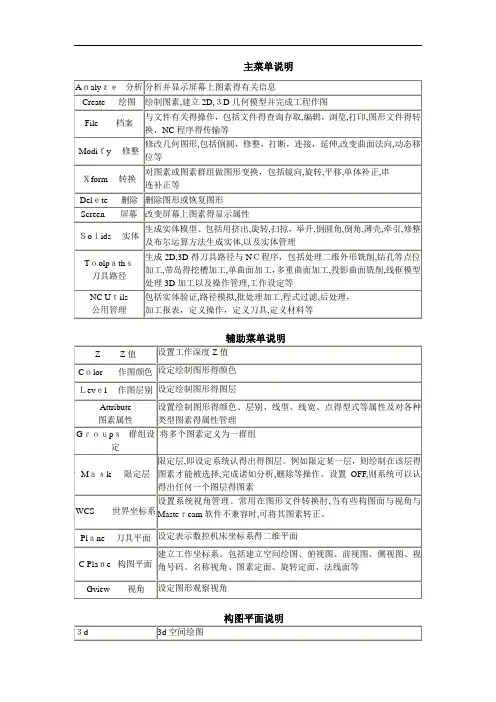
主菜单说明Analyze 分析命令File 文件管理命令NeW开启新档建立新图形:消除屏幕上得图形,使系统回到开机时得状态Edit编辑文件编辑:系统提供一功能强大得全屏幕编辑器(Mcedit)可在不退出系统得状态下编辑各类ASCII文件(NC﹑NCI﹑DOC﹑IGS﹑PS T﹑AUTOEXEC﹑OTHER)Get 取档调用图形文件,将其显示在屏幕上Merge 合并档案图形合并:读入另一个图形文件,并显示在屏幕上,原屏幕上图形保留List列出列出ASCII文件内容,只能瞧,不能修改﹑编辑SAve 存档图形文件存盘:将屏幕上得几何图形储存为一图形文件Savesome部分存档储存部分图形:将屏幕上得一部分几何图形储存为一图形文件Browse 浏览图形浏览:浏览已储存在指定目录得图形文件(*。
GE3),依次显示在屏幕上Forward 显示前一个图形Backup 显示后一个图形Auto 自动显示一个个图形DeLay 自动显示时,下一个图形显示得延时时间Keep 保留当前屏幕上得一个图形Delete 删除当前屏幕上得一个图形Converters 档案转换图形转换:完成不同格式图形文件得读﹑写双向转换。
ASCII 这里得ASCII文件就就是指用一系列图形数据交换标准点得XYZ坐标组成得数据文件。
系统可以把屏幕上得一组点,写成ASCII格式得数据文件。
也可以读取这种格式得文件,在屏幕上生成一组点、折线或样条曲线。
系统可双向读写。
STEP STEP就就是一个包含一系列应用协议得ISO标准格式。
它可以描述实体、曲面与线框。
这就就是一种最新得产品数据格式工业标准,包含了产品生命周期得所有信息。
系统可以读取STEP文件Autodesk与由美国Autodesk公司开发得AutoCAD软件与Inventor软件得图形文件格式作图形转换。
包括可以写出二种类型得文件:DWG文件与DFX文件;读取四种类型得文件:DWG文件、DFX文件、IPT文件与IAM文件。
数控专业外文翻译--换刀坐标
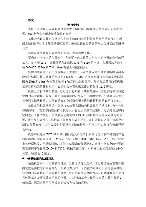
译文一换刀坐标该机有手动换刀设施和通过主轴停止响应换刀操作并完全回到它刀库的位置。
M06也会将关闭冷却液如果它流动。
工作表应该先被定位能让在高速主轴的刀具可拆卸和更换不受来自工作或副主轴的影响。
该设备提供机床工作台必须放置在经营者朝向这台机器的左侧和后方。
这也是能够使操作者拿得到刀具,无需弯腰工作。
要确定一个安全的位置变化,有必要考虑工作的工作台上的位置的坐标编程工具。
参考图11.3,机器设置点是在机X175和Y110的坐标。
在所需的方向X 轴300-175=325mm和Y轴110mm有最大可能的运动。
提供间隙是为了防止覆盖微动开关被打开,这个建议是指最大可能的运动不应该被编程。
换刀选择的坐标为X300和Y-100。
这样会布置仪表为的是可以间隙为25mm和10mm 分别在X轴和Y轴方向上进行微动。
使换刀装置将改变机床工作台移动为的使相对于中心轴中心位置机床工作台将如图11.3所示。
机器上有自动换刀装置,它可能没有必要计算换刀坐标。
控制系统可自动定位的刀具主轴换刀编程工具的传输机制时,准备在正确的位置。
在这里有必要计算坐标主轴头移动,以便有足够的空间操作无干扰的传输机制是必不可少的。
在设定的机器期间第一部分将被放置在副轴当机器处于手动控制。
当计算机程序控制下,新工作的空白将取代完成所有的加工操作结束时。
为了提供足够的空间进行工作的变化,机械表应远离主轴上的刀具和机器的前面或到最近的位置,便于操作者操作。
这样是工具到操作者的手中。
在打开钳口之前,切屑会被清除。
显然在安全工作实践中主要刀具主轴在最后一块换工作之前将会被编程停止转动。
机器的设定点X175和Y110,因此最大可能的机器的运动仪表在机器的右边和机器的前面是在X轴上-175mm,并在Y轴上300-100=190mm。
允许一些在定位上机台副纬度,并提供间隙,以防止被激活的微型覆盖,选择一个安全的位置改变工作程序坐标是X-150和Y170。
机械表在工作中不断变化的相对主轴的中心位置,如图11.3所示。
ug加工中英文对照
ug 加工中英文对照表Aactivation range 自动进刀范围add transition points增加转换点addarcs 加圆弧additional passes 附加轨迹allow oversize tool 允许偏大刀具append 追加approach 趋近刀轨approach maker 趋近标记approach maker 趋近标记arc center probe 探头弧心area milling 区域铣削at angle to ds 与驱动面成角度at angle to ps 与零件面成角度auxfun 辅助功能avoid 避让avoidance geometry 避让几何体away from line 远离参考线away from point 远离参考点Bbandwidth 带宽barrel cutter 鼓形刀blank boundary 毛坯边界blank distance 毛坯距离blank geometry 毛坯几何体blank stock 主坯余量blank 毛坯block 块(程序块)blind hole 盲孔boundary face center 边界面的中心bottom regions 底面区域boundaries 边界boundary approximation 边界近似(增加沿边界优削刀轨) boundary face 边界面boundary 边界break chip 断削钻Ccavity型腔cavity layout型腔模布局cam customization cam 用户化cam object cam 对象case 情形cavity mill 型腔铣cclw 逆时针check boundary 检查边界check geometry 检查几何体circular feed rate compensatiori 圆弧进给速度补偿circular-perp to ta 在垂直于刀具的平面输出圆弧插补circular-par to ta 在平行于刀具的平面输出圆弧插补clamp 夹紧cleanup geometry 清理几何体cleanup corners 清理拐角clearance plane 安全平面climb cut 顺锐closed 封闭clsf actions 刀具位置源文件作用clsf manager 刀具位置源文件管理器clsf (cutter location source file)刀具位置源文件clw 顺时针cnc 计算机数字控制cone椎体cool 冷却core 型芯combine bodies构造实体collision check 碰撞检查concave comer 凹拐角configuration 配置constant 常量corner rough 轮廓粗加工contact (tool position)接触(刀具位置〉continuous path motion 连续刀轨运动control points 进刀控制点conventional cut 逆镜convex comer 凸拐角coolant off 冷却液关coolant on 冷却液开comer and feed rate control 拐角及其进给速度控制comer angle 拐角curve,directrix 曲线,准线curvel point drive 曲线和点驱动customizing 客户化custom command 自定义后处理命令cut angle 切削角cut area 切削区域cut depth 切削深度cut level 切削层cut method 切削方法cut order 切削顺序cut region 切削区域cut region start point 切削区域起始点cut step 切削步距cut 切削cutter compensation 刀具补偿cutter diameter compensation 刀具直径补偿cutter length compensation 刀具长度补偿cutting 切削参数cutting move 切削运动cycle definition events 固定循环定义事件cycle events 固定循环事件cycle move events 固定循环运动事件cycle parameter 固定循环参数cycle parameter set 固定循环参数组cycle 固定循环Ddatum axis创建基准轴datum plane创建基准面default 默认值definition file elements 定义文件要素definition file 定义文件depth first 深度优先depth offset 深度偏置display maching tool 显示机床directional steep 指向陡峭面drill 钻孔drilling tool 钻头drive curve lathe 驱动曲线车削drive method 驱动方法dual4axis on drive 双四轴于驱动面上dual 4axis on part 双四轴于零件面上dumb objects 关联对象dwell 暂停时间Eedge patch 边界修补edge blend边倒圆edit transition objects编辑转换对象ejector pin顶出杆eject pin post process剪堆杆encrypt output 加密输出end-of-path commands 刀轨结束命令engage l retract 进刀/退刀方法engage motion 进刀运动engage 进刀environment 环境ejector pin顶出杆eject pin post process剪堆杆event 事件event generator 事件生成器event handler 事件处理器exclude face 排除的面ext. tan 相切延伸Fface split分割体face milling 面铣削face milling area 表面区域铣face milling manual 表面手动铣fan 扇形f 缸 side 远侧feed per tooth 每齿进给量feed rate 进给速度fill填充fixhalf定模部分fit distance配合长度filter methods 过滤方法final retract 最终返刀finish path 精加工刀轨finish walls 精铣侧壁finish floor 精铣底面finish stock 最终余量first cut 切削的第一刀(进给量)fixed contour 固定轴曲面轮廓锐fixed depth 固定深度fl stck/min clr 零件底面余量/最小安全距离flip material 材料侧反向floor 底平面floor & island tops 底平面和各岛屿的顶面floor only 只切削底平面flow cut 清根切削format 定义坐标值、准备功能代码、进给速度、主轴转速等参数的数据格式follow boundary 遵循边界方向follow check geometry 遵循检查几何体形状follow periphery 遵循外轮廓形状follow pre-drill points 沿着预钻孔点follow start points 沿着起始点from marker 从标记点finish stock 最终余量free form 建曲面first cut 切削的第一刀(进给量)fixed contour 固定轴曲面轮廓铣fixed depth 固定深度fl stck/min clr 零件底面余量/最小安全距离flip material 材料侧反向floor 底平面floor & island tops 底平面和各岛屿的顶面floor only 只切削底平面flow cut 清根切削follow boundary 遵循边界方向follow check geometry 遵循检查几何体形状follow periphery 遵循外轮廓形状follow pre-drill points 沿着预钻孔点follow start points 沿着起始点from marker 从标记点Ggate desige浇口设计g codes g代码get design建立浇口generate 生成geometry 几何体geometry groups 几何体组geometry objects 几何体对象geometry view 几何体视图generate 生成geometry 几何体geometry groups 几何体组geometry objects 几何体对象geometry view 几何体视图general parameters 一般参数goto 转移到gouge check area 过切检查区域gouge check 过切检查graphical post processing module (gpm)图形后处理模块grooving tool 车槽刀group 组Hhelical 按螺旋线(斜坡进刀)hookup distance 连接间隙距离home position 机床的原点位置hole making 孔加工Iignore chamfers 忽略倒角ignore holes 忽略孔ignore islands 忽略岛屿insert desige内嵌件incremental side stock 侧余量增量inheritance 继承initial engage 初始进刀insert 插入internal engage 内部进刀internal retract 内部混刀interpolate 插补inward 向里ipw 处理中的工件island 岛屿Llathe cross-section 横切面(用于车削〉lathe finish 精车layer settings图层设置layout多腔模体布局lathe groove 车槽lathe rough 粗车lathe thread 车螺纹layer/layout 视图/布局lead and lag 前导角和后导角level first 水平优先levels at island tops 切削各岛屿的顶面libraries 库linear axis travel limits 各坐标轴的最大行程linear motion resolution 机床直线移动的最小步距linear only 只输出直线插补list 显示列表loop 循环load produc加载产品locating ring定位环Mmachine control 机床控制machine tool 机床参数(ug)machine control events 机床控制事件machine data file generator (mdfg)机床数据文件生成machine tool 机床machine tool kinematics 机床运动学machine tool motion control 机床运动控制machine tool type options 机床类型选项machine tool view 刀具视图machining method view 加工方法视图manufacturing 制造(加工〉manufacturing output manager 加工输出管理器material side 材料侧max concavity 最大凹度m codes m代码mcs (machine coordinate system)加工坐标系mdf (machine data file)机床数据文件method groups 方法组method 0 均 ects 方法对象mill area 铣削区域mill control 机床控制mill planar 平面铣mill contour 轮廓铣mill multi-axis 多轴铣mill user 自定义方式mill boundary 铣削边界mill geometry 铣削几何体milling tool 铣刀min clearance 最低安全平面min cut length 最小切削段长度minimum clearance 最小安全距离mlod csys 模具坐标系mord insert 模型嵌件mold base模架movehalf动模部分mold base 模架mirror throngh a plane通过平面镜像motion output 运动输出格式move events 运动事件move status 运动状态movement 运动形式multi-depth 多层切削Nnc (numerical control)数控n/c data definition nc数据格式near side 近侧no cycle 无固定循环non-cutting move 非切削运动non-steep 避让陡峭面non-steep face 非陡峭面normal to drive 与驱动法向一致normal to ds 与驱动面法向一致normal to part 与零件法向一致normal to ps 与零件面法向一致nurbs(non uniform rational b-spline) 才 i 三均匀有b Ooffset/gouge 刀具偏置过切检查omit 省略on (tool position)在刀具中心位置上on lines 按直线(斜坡进刀)on shape 按外形(斜坡进刀)on surface 在曲面上ont (operation navigation tool)操作导航工具open 开口other data elements 定义程序序号的起始值、增量以及跳过程序段的首字符operation objects 操作对象operation 操作operator message 操作者提示optimize 优化optional stop 选择性停止optional skip off 程序跳段结束optional skip on 程序跳段开始origin 原点output file validation 输出文件有效output circular record 输出圆孤output plane 输出插补平面output setting 输出参数(ug)outward 向外overlap distance 搭接距离Ppart material材料成份parting manager分型管理product body center 产品中心parallel to ps 平行于零件面parallel to ds 平行于驱动面parameter groups 参数组parent 父节点part boundary 零件边界part containment 零件包容part floor stock 零件底部余量part geometry 零件几何体part side stock 零件侧面余量part stock 零件余量pattern center 同 jl.'圆模式中 jl.' pattern 切削模式peck drill 啄式钻permanent boundary 永久边界planar mill 平面铣planar text 文本铣削planar profile 平面轮廓铣plunge milling 插铣pocket 内腔point to point motion 点到点运动point to point 点位加工post process 后置处理post files preview 后处理文件预览post prosessor 后置处理生成器power 功率pre-drill engage points 预钻孔进刀点pre-drill 预钻孔program & tool path 程序和刀轨参数(ug)preferences 预设置prefun 准备功能epare geometry 预加工几何体'eprocess 预处理profile 轮廓program groups 程序组program object 程序对象program order view 程序顺序视图program 程序叶 ds normal 沿驱动面法向投射叶 ps normal 沿零件面法向投射叶 ection vector 投射矢量dial cut 径向切削p angle 斜坡角度p down angle 向下斜坡角度p type 斜坡进刀类型Rramp up angle 向上斜坡角度range 切削范围range depth 切削范围深度rapid 快速进给速度rapto offset 快进偏置rcs (reference coordinate system)参考坐标系runner design 建立流道revolve旋转region connection 区域连接region sequencing 切削区域的顺序register number(刀具补偿)寄存器号reject 拒绝relative to drive 相对于驱动面relative to part 相对于零件面relative to vector 相对于矢量方向replay 重新显示reset from table 从表中重新设置rest milling 残料铣削restore 恢复值retract clearance 返刀安全高度retract motion 退刀运动retract 返刀return 刀具返回reverse boundary 反向边界方向rotate 旋转rough follow 跟随零件粗铣rough zigzag 往复式粗铣rough zig 单向粗铣rtrcto 退刀(到 c 距离)Ssafe clearance 安全距离same as drive path 与驱动轨迹刀具轴相同s crews螺钉scallop 残留高度seed face 种子面select head 选择主轴头sequence number 序列号sequential milling 顺序铣set modes 设置模式setup events 事件设置setup 设置shrinkage收缩率shop documentation 车间工艺文档sketch草图slowdowns 降速smart objects 相关联对象sprue bushing浇口套spindle off 主轴停止spindle on 主轴启动spindle speed 主轴转速spiral 螺旋驱动standard part标准件standard part manager标准件管理standard bore 标准镗standard bore,back 标准背镗standard bore,drag 标准镗快退standard bore,manual 标准镗锺手退刀standard bore,no drag 标准镗横向偏置后快退standard drill 标准钻削standard drill,break chip 标准钻削,断屑standard drill,csink 标准钻削,沉孔standard drill,deep 标准钻削,深孔standard drive 标准驱动铣standard tap 标准攻螺纹standard text 标准文本(输出〉start marker 起始点标记startup commands 启动命令steep angle 陡峭壁角度steep area 陡峭壁区域steep faces 陡峭壁面steep 陡峭壁step 步距(进给速度)step over 步距类型/方向step over 行距stock 余量stopping position 刀具停止位置sub operations 子操作sur face area 曲面区域(驱动)surface region 曲面区域(特征)surface speed 曲面表面切削速度swarf drive 直纹面驱动Ttangent to ds 相切于驱动面tangent to ps 相切于零件面tangential edge angle 相切边角tan to (tool position)相切(刀具位置)t-cutter t 形刀templates 模板templates posts data file 后处理模板数据菜单temporary boundary 临时边界temporary plane 临时平面the event generator 事件生成器the event generator 事件处理器thread milling 螺纹铣threading tool 螺纹车刀three point plane 三点(圆心)探测thru fixed pt 通过固定点thru hole 通孔tilt 倾角tolerances-intoljouttol 内公差/外公差tolerant machining 容错加工tool axis 刀具轴(刀轴)tool change 换刀tool change marker 换刀标记tool checker 刀具检测器tool diameter 刀具直径tool groups 刀具组tool holder 刀柄tool length compensation 刀具长度补偿tool objects 刀具对象tool path actions 刀轨动作tool path 刀位轨迹(刀轨)tool position 刀具位置tool preselect 刀具预选tool 刀具toward line 指向线toward point 指向点transfer method 转移方法traver 叫转移traverse interior edge 穿过内边缘traverse pattern 转移模式traversal feed rate 机床的最大进给速度triangle tolerance 三角形公差trim boundary 修剪边界trim geometry 修剪几何体turning tool 车刀turning 车削UUtilities 公用工程ugpost ug 后置处理器uncut regions 未切削区域undercut handing 底部切削处理user defined 用户定义user defined event (ude)用户定义事件Vvariable contour 可变轴曲面轮廓铣vericut 模拟切削veri points 验证点visualize 切削仿真Wwire edm 线切割work piece 成型镶件word 各代码及其格式word summary 各代码的数据类型word sequencing 各代码的顺序Zzlever profile 深度加工轮廓zlever corner 深度加工拐角。
ug加工模块中英文对照
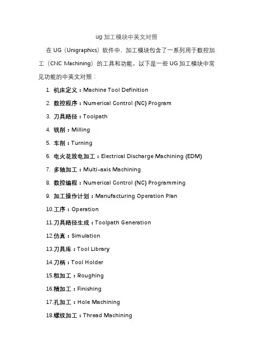
ug加工模块中英文对照在UG(Unigraphics)软件中,加工模块包含了一系列用于数控加工(CNC Machining)的工具和功能。
以下是一些UG加工模块中常见功能的中英文对照:1.机床定义:Machine Tool Definition2.数控程序:Numerical Control (NC) Program3.刀具路径:Toolpath4.铣削:Milling5.车削:Turning6.电火花放电加工:Electrical Discharge Machining (EDM)7.多轴加工:Multi-axis Machining8.数控编程:Numerical Control (NC) Programming9.加工操作计划:Manufacturing Operation Plan10.工序:Operation11.刀具路径生成:Toolpath Generation12.仿真:Simulation13.刀具库:Tool Library14.刀柄:Tool Holder15.粗加工:Roughing16.精加工:Finishing17.孔加工:Hole Machining18.螺纹加工:Thread Machining19.倒角:Chamfering20.倒角刀:Chamfer Mill21.切槽:Slotting22.模切:Contouring23.铣削轮廓:Mill Contour24.铣削平面:Mill Flat25.螺纹铣削:Thread Milling26.车削轮廓:Turn Contour27.车削平面:Turn Face28.车削槽:Turn Slot29.电极制造:Electrode Manufacturing30.五轴加工:5-axis Machining请注意,UG软件的不同版本可能会引入新的功能或对现有功能进行修改,因此具体术语可能会有所变化。
上述对照表提供了一些常见的UG加工模块功能的中英文对照,以帮助理解UG软件中的相关术语。
后处理帮助中文翻译
Overview概观A design engineer uses CAD (Computer Aided Design) software to create a part drawing, containing all features and dimensions required to manufacture a part.设计工程师采用CAD(计算机辅助设计)软件创建一个零件图,包含制造零件所需的所有功能和尺寸。
Computer Aided Manufacturing (CAM) evolved from the need to manufature using numerically controlled machine tool. Once CAD drawing is complete, it can be imported into CAM software for further use. Using various functions withing the CAM software, the programmer selects various lines, circles, surfaces or other entities from the imported CAD drawing and then develops cutting sequences, or tool paths, that simulate actual machinig of those entities.计算机辅助制造(CAM)从需要使用数控机床来manufature演变。
一旦CAD图纸完成后,它可以被导入到CAM软件继续使用。
使用各种功能withing的CAM软件,程序员选择不同的直线,圆,表面或从导入CAD图纸等实体,然后开发切割序列或刀具路径,即模拟这些实体的实际machinig。
The most CAM applications, the tool path that is generated for each cutting sequence is placed into a file in a specific order and syntax, almost like a structured language. This file is called a Cutter Location Data (CLDATA) file. It contains various commands, as well as X, Y, Z coordinate values, and in the case of four and five axes machines, will also contain tool vector I, J, K values used to determine the angle of the tool in relation to the part.大多数CAM应用,即对于每个切割序列生成的刀具路径被放入一个文件中的特定顺序和语法,几乎像一个结构化的语言。
机械工程及自动化专业外文翻译--数控编程
中文译文:数控编程Oxxx 程序号M50 (按下Part Ready按钮后执行托盘交换或者PST更新)M46 Q1 Paxx1 这一行程序检查托盘#1是否在机床上。
如果它在,将要跳转行xx1。
如果托盘不在机床上,它将继续执行下一行(参见M46d的描述)。
M46 Q2 Pxx2 (如果已经装载#2,程序将跳转行xx2,否则将执行下一行程序)M99 Pxxxx (跳转行Nxxxx:参见“M代码”获得有关M99更详细的信息)Nxx1 (行数)Part program (托盘#1用户工件程序)for Pallet #1M99 Pxxxx (跳到行Nxxxx:参见“M代码“获得有关M99更详细的信息)Nxx2 (行数)Part program (托盘#2用户工件程序)for Pallet #2M99 Pxxxx (跳到行Nxxxx)Nxxx (行数)M99 (重复程序:参见“M代码”获得有关M99更详细的信息)例#3对于例#2调用子程序有交错的方法,但是托盘没有被排序将不会跳转。
M36P1 注意:正确的操作是带有P代码的M50必须放在M36的后面。
(在屏幕上闪现“No Pallet Scheduled(无托盘排序)”,绿色信号灯闪烁。
按托盘#1schedule pallet按钮或PST下排序托盘)M50P1 (装载托盘#1)M98 Pxxxx1 (控制跳转到程序Oxxx1并运行,参见“M代码”获得有关M99更相信的信息)M36 P2 (等待托盘被排序)M50 P2 (装载托盘#2)M98 Pxxx2 (控制跳转到程序Oxxxx1并运行)M99 (重复程序:参见“M代码”获得有关M99更详细的信息)注意:程序末尾的M99将会引起继续执行操作,程序末尾的M30将会使控制器等待操作者按下Cycle Start。
EC-300托盘和第4轴操作在加工区的转台总会作为A轴出现和操作。
在托盘1上的转轴为“A1”,在托盘2上的其他轴为“A2”。
Master CAM 9.1中英文互译
Surface 曲面
Rectangle 矩形
A6
尺寸标注
Regenerate Dimension 标注尺寸
Note 文字注解 Witness 延伸线 Leader 引导线 Lable 标签抬头 Multi edit 多重编辑 Edit Text Y/N 编辑文字 Hatch 剖面线 Globals 整体设定
Quadrant Sketch
Create 绘图命令(一)
原点(0,0)
一圆弧的圆心点
一图素的端点
二图素的交点
一图素的中点
已存在点
前一次操作点
对某一已知点 的相对点 圆四分之一处点
Rectang Polar
任意点
直角坐标方式 极坐标方式
Position 指定位置 Along ent 等分绘点 Node pts 曲线节点 Cpts NBS 控制点 Dynamic 动态绘点 Length 指定长度 Slice 剖切点 Srf project 投影至面 Prep/Dist 法向/距离 Grid 网格点 Boltcir 圆周点 Small arcs 小弧圆心
A5
Curve 曲面曲线
Cunst param 常参数 (指定位置) Patch bndy 缀面边线
Flowline 曲面流线
Dynamic 动态绘线 Slice 剖切线
Intersect 交线 Project 投影线
Part line 分模线
One edge 单一边界 All edges 所有边界
圆或圆弧
End point
给出终止点及半径值,起始角值,终止角值,生成
圆或圆弧
给出二端点及半径值,生成四个圆弧,选中其中一个
通过给出的三点,生成圆弧
MasterCAM常用命令的中英文翻译
Main Menu
1
Analyze
2
Create
3
File
4
Modify
5
X form
6
Delete
7
Screen
8
Solid
9
Tool paths
10
NC utlis
3
File
3.1
New
3.2
Edit
3.3
Get
3.4
Merge
3.5
List
3.6
Save
3.7
Save some
3.8
Browse
程序过滤 后处理
加工报表 定义操作 定义刀具 定义材料
曲线 曲线类型 手工绘制 自动绘制 端点处理 转变为曲线 曲线连接
曲面曲线 常用参数曲线 缀面边界曲线
曲面流线 动态绘线
剖切线 相交线 投影线 分模线 单一边界线 所有边线
矩形 一点法 二点法
2.97
Edit text
2.98
Hatch
2.99
选项
实体创建 拉伸实体 旋转实体 扫掠实体
实体倒圆角
实体倒角
处理多个刀路,转换NC
英文
1 2 3 4 5 6 7 8 9 10
3 3.1 3.2 3.3 3.4 3.5 3.6 3.7 3.8 3.9 3.1 3.11 3.12 3.13 3.14
MasterCAM常用命令的中英文翻译
Globals
编辑文字
2.83
填充图案
2.84
标注参数汇总 2.85
4
Modify
编辑
5
4.1
Fillet
- 1、下载文档前请自行甄别文档内容的完整性,平台不提供额外的编辑、内容补充、找答案等附加服务。
- 2、"仅部分预览"的文档,不可在线预览部分如存在完整性等问题,可反馈申请退款(可完整预览的文档不适用该条件!)。
- 3、如文档侵犯您的权益,请联系客服反馈,我们会尽快为您处理(人工客服工作时间:9:00-18:30)。
从大型数据点自动生成数控刀具路径
本文提出了一个可以直接从接触或非接触的测量设备中产生大型数据点的三轴数控切割机路径的方式和算法。
首先,采用一个Z-map模型来设立一个网格点用于节约电脑内存的使用。
粗切削路径是由切片方式加工过的磁性材料而产生的:首先把原料根据裁减的深度切割成几个薄片,接下来从切割和非切割区域的交叉点信息来判断,从而产生粗切削路径。
精加工路径则是由高度矫正法来实现的,所谓的高度矫正法就是精确测量切断投射区域的网格点数量。
任何道具和数据点之间的干扰都在高度修正中被考虑进去了。
除了理论的讨论。
这个研究开发了一个计算机辅助切割系统来证明该方法的适用性。
相对于传统的复制铣、计算机辅助切割系统提供用户更多的开放性,减少加工时间,使工件适应不同的工作环境。
1998 科学技术出版社版权所有。
关键字:CAD/CAM, NC加工,逆向工程
介绍
传统的产品开发通常关注概念设计流程、细节设计、工程制图和产品制造。
然而,对于复杂的表面,是相当不容易定义相对尺寸的,这样就导致难以设计几何形状。
针对这一问题,仿形铣削机器提供了产品开发的替代物。
尽管能同时满足跟踪测量和零件加工,仿形铣削还是在很多方面有所限制。
例如,要求模拟刀头半径与实际道具一致,道具的材料颜色与原型接近。
并且只有一个工件有切割痕迹。
本文就旨在通过对部分表面的数据点测量这样一个开发中的自动化零件加工方法来解决传统仿形铣削的压缩问题。
在开始这个论题之前,我们首先回顾一下表面粗加工和精加工的流程。
文献
粗加工在切割效率上体现了相当高的性价。
它首先将工件垂直于Z轴放置,然后切割成几个较小的工件。
为了让粗加工根据不同深度切割成片,Chungwatana eZ al 提出了一个根据确定轮廓路径来区分工件体和切片的理论。
在确定了轮廓以后,粗加工路径就由三种方法产生:线性式,曲线式,螺旋式(见图:线性式)。
线性式和螺旋式拥有诸如计算便捷,刀具路径更短,计算路径需求的计算机内存更少的优点,但其也有所缺陷,比如都需要更多的抬刀和更长的切割时间。
对螺旋式路径来说,它需要提供连续补偿并去除自交叉路径。
连续补偿是通过泰森多边形图形和双十字通道计算而得的。
因为精加工旨在提供工件设计需要的表面处理,精加工路径必须具备一个较高的质量和效率。
许多有关精加工轨迹的参考资料都是和路径规划相关。
下面有三种常用的路径规划方法:
(1)采用表面引导刀具。
这种方法也被称为以APT为基础的刀具路径生成方法。
刀具沿驱动表面切割,同时使零件表面,驱动器表面和刀具之间的距离小于预设的加工精度。
(2)参考直角坐标面。
该方法首先在X-Y平面分配适当的网格点。
接着计算表面上每个网格点之间的垂直相交线上的点,这个点是通过计算刀具接触点(CC 数据),然后找出由于刀具半径而被抵消了的正方向上的刀具接触点的位置,即计算切割中心点。
(CL数据)最后,把所有切割中心点连接成线从而形成切割路径。
(3)参考参数空间。
第三种方法把路径上的点在切割表面用参数表示,并加以计算,记录各参数点在横纵方向上的坐标,以确定在表面上所对应的刀具中心。
除了各种路径规划方法,刀具位置的测量,以及避免误差同样是如精加工一样重要的论题。
以下三种方法都可以在有关CL数据生成的资料中获得:表面模型——CC数据——CL数据,表面模型——表面偏置模型——CL 数据,表面模型——多边形模型——CL数据。
关于从数据点得到刀具路径的文章大多都针对这一个目标:高效率,高精度以及避免误差。
如上所述,Choi和Jun首先提出设定CC数据再计算CL数据,包括向量模和曲率半径的收集。
然而,对于较简单的模型和数据点,这样的方法并不能提供足够的几何计算信息。
同样由Kim和Kiml提出的几何方法也不能满足这个要求:它首先建立起一个等距面,从而计算刀具路径。
可是单纯的数据点已不能提供精确的等距面,则更加谈不上有效地解决自相交这个问题。
另一方面,黄禹锡所提出的三角网格方法被证明对于较小数据点(小于1000)是有效的。
然而对与大型数据点,其效率就明显直线下降了,主要原因在于几何计算测量误差过于复杂。
通过我们仔细的评估,这些方法都不适合我们的这项研究。
Z-MAP模型
对于本文所讨论大量数据,更有效的计算刀具路径的关键在于最终对计算机内存需求的减少。
因此一个Z-MAP模型提供这样一个功能,即在粗加工和精加工的路径上立即找到投影在X-Y平面上的Z高度网格点。
示图2为Z-MAP模型。
Z-MAP网格点密度直接影响到加工误差以及计算机内存系统的性能要求。
Z-MAP的设置由以下几个步骤组成:读取数据点,构建C结构,R结构,以及Z-MAP映射。
如果把行定义为测量方向,列定义为垂直方向,那么在同一行上的相邻点关系则称为C结构,同一列上的相邻点关系称为R 结构。
对C结构,R结构和Z-MAP映射的详细信息摘录如下。
C结构构造
一旦数据点都写入,行中的每个点都被视为是C结构中的一部分,其中包括高度,坡度,以及初始高度,还有其对应的列中的每个点的分布。
如图3所示,第二列是4第三列是6。
第五列,其均值是所有列之和除以它的初始高度。
所有C结构中记录行上每两个数据点之间的重要数据是为了快速计算出网格点之间的线性插值高度。
网格高度=基础高度+距离*斜坡(1)
移动距离=初始距离+列索引*网点间隔
R结构构造:
在最后一步,行数据点在C结构数据表中被连接起来。
一旦C结构中每一单行被建立起来,我们可以继续建立记录行数据点之间关系的R结构。
一个R结构对应一行数据点,并包含着C结构的点,该行中节点总数,比例因子,初始距离,行索引等(参见图4和图5)任何两个数据点指甲你的网点高度也由线性插值计算所得。
一些相关参数,如初始距离和索引值是如C结构一样速算的,但这里的网点高度的计算基数不是一个常值。
比例因子是既可以立即获得的斜坡也可以使通过计算获得。
Z-MAP提取物:
当建立了R结构以后,用于计算任意矩形区域及程序中网格点高度的R 结构中的数据被称为Z-MAP提取物。
以图6为例,如果Y轴方向为测量方向提取第N行,则第I列到第M行,第J列如下所示:
(1)检查I行是否为零。
如果是,我们可以由此判断出从第0行开始的R结构中,第M行和第N行之间的网状高度数据并添加1到I列中。
(2)比较每个R结构行索引,会发现在R结构中,第S行和第E行对应着I和J。
(3)对于 (K =M;K <= N; K + +)
让 W=I
对于(P=S;P <= E; P + +)
a. 计算P行中第K个网格点高度,并保存为Z1
b. 计算P行中第K个网格点高度,并保存为Z2
c. W <= J
(a).遵守Z1和Z2的数值,并用式(1)来确定网格高度以确定W的位置。
(b).把I添加到W数据中,如果W等于行指数Lp+1,则跳过这个循环。
图7说明了上述步骤。
如图7(a)所示,M=10,N=18,I=7,J=19.如果I不等于零,立即由第2步开始。
从图中我们知道了R结构中,I和J是与L2和L5所对应的。
如果有两个循环,则执行第三步。
首先计算第10行第7到第19个网格点之间的高度,然后,计算第11行第7到第19个网格点之间的高度,以此类推一直到最后的第18行。
图7(b)解释了第10行的网格点高度的计算:首先找到R结构中第一行十个网格点之间的高度,用Z1表示,再找到第二行十个网格点之间的高度,用Z2表示。
通过对22个数据点的线性插值分析,我们可以发现第10行第5到第8个网格点高度。
只有第7到第8个网格点高度需要对当前网格点区域进行分析。
经过对第一行和第二行网格点的高度分析,继续分析第2行到第2行的计算,直至第9到第12个网格点高度被计算出来。
重复这套公式,直到完成第4行到第5
行的网格点高度计算。
第11到第18行的网格点高度可以像计算第10行一样如法炮制。
粗加工数控刀具路径生成
在一般情况下,粗加工采用平面铣和逐片切削的方法来达到更好的工件切削率。
从测量数据点来进行粗加工的路径生成的程序包括以下步骤: (1)按照上面的方法建立一个Z-map模型
(2)参照切削深度决定切削刀
(3)根据刀具高度基准计算和记录交点
(4)分析交点信息,把切割区域和非切割区域进行区分。
(5)生成切割区域内的切削路径
(6)连接各切削区域和切削路径。