科密fz03说明书
科密A1考勤管理系统的说明书讲解
科密A1考勤管理系统的说明书第一章系统功能特性A1考勤管理系统是以用户需求为导向,针对各工厂、公司考勤管理业务进行计算机管理而开发的通用考勤管理系统,目前主要分为写字楼版和工厂版两个版本。
其中写字楼版功能简单易用、允许设置多个班次、按周循环上班、无需排班,适用于写字楼型的简单考勤;工厂版功能强大、可以按天/周/月排班,轮班、可自定义考勤项目、考勤制度配置灵活、报表丰富,适用于工厂型的复杂考勤。
系统采用流行的下拉式菜单,多文档操作模式,界面清晰舒适,直观性强,操作简便,增强的在线帮助功能,安全可靠。
系统查询、汇总、计算快速简捷。
A1考勤管理系统由主管人员设定操作人员的权限,可由操作人员定义自己的口令密码,有效的防止了非法使用和越权使用系统。
系统具有严格的数据录入容错体系,防止了误操作和非法数据录入。
系统备份功能保证了数据不会丢失,在系统发生故障时,可迅速恢复运行。
A1考勤管理系统具有六大功能模块,分别为人事管理、终端管理、考勤管理、门禁管理(选择门禁机时才会有这个模块)、系统维护、帮助。
第二章系统要求一、硬件要求:1、CPU:1GMHz以上2、内存:128MB以上3、硬盘:2GB以上的可用硬盘空间4、通讯端口(COM口):一个(如为USB接口,则需一条USB转COM口的转接线)二、运行环境1、单机运行数据库:MSDE 2000操作系统:WIN98/2000/ME/XP/NT/20032、联网运行数据库:MS SQL SERVER 2000以上企业版/标准版工作站操作系统:WIN98/2000/ME/XP/NT服务器操作系统:WINDOW NT/2000/2003 SERVER第三章软件的安装与数据库连接3.1 单机版安装1、获取安装程序,安装包中的文件分两部分:A1考勤管理系统安装包、MSDE(Microsoft Sql Server Desktop Engine)。
2、运行Setup.exe,开始安装系统3、选择所要使用的语言,单击“确定”。
骇客mt03说明书

黑客mt03说明书
黑客mt03用户菜单系统菜单
用户菜单设置:在运行状态下,按住“设置/查看”键持续5秒以上至“显示温度”显示窗显示“SET”时,则表明进入用户菜单设置,“开机温度”指示灯亮,以后每按下并立即松开“设置/查看”键一次,则进入下一项参数设置(可循环操作),相应的参数指示灯亮。
进入用户菜单后,按“▲”或“”键可修改“停机温度”显示窗里的设定参数。
系统菜单设置:在运行状态下,同时按住“设置/查看”与“”键持续5秒以上至“显示温度”显示窗显示“F1”时,则表明进入系统菜单设置,以后每按下并立即松开“设置/查看”键一次,则进入下一项参数设置(可循环操作)。
进入系统菜单后,按“▲”或“”键可修改“停机温度”显示窗里的设定参数。
参数指示灯全灭。
在参数设置状态下按住“设置/查看”键持续3秒以上或30秒内无按键动作,则退出参数设置状态。
用户菜单查看:在运行状态下,按住“设置/查看”键持续3秒至“开机温度”指示灯亮时,并按下并立即松开“设置/查看”键一次,将查看下一项参数(可循环操作),相应的参数指示灯亮。
在参数查看状态下,无法修改所设定的参数。
在参数查看状态下按住“设置/查看”键持续3秒以上或10秒内无按键动作,则退出参数查看状态。
“显示温度”显示窗显示当前库温。
“化霜余时”键说明。
TF03 三代TF系列超音波距离传感器说明书

IntroductionAs the third generation product of TF series, TF03 inherits the cost-effective andcompact-integration advantages from the previous two generations. Meanwhile, TF03 upgrades more than ten key parameters and offers multiple expansion functions to meet the various demands in different application scenarios. We have two detection ranges for you to choose: 100m and 180m. With a small size of 44×42.9×31.8mm, it can be covered by just a palm of one hand. The product is applicable to the terrain following of drones, the collision avoidance of cars, intelligent transportation and industrial safety warning.TF03 employs the pulsed time-of-flight principle. The unique design of the optical system and the signal processing circuit improved the detecting performance in a compact size. In addition to increasing the range to more than 100 meters, this sensor features 0.1m blind zone, ±10cm accuracy, up to 10KHz frequency and 100Klux ambient light immunity. TF03 also contains a compensation algorithm targeting outdoor highlight environment, so that it can still keep excellent performance in harsh environment.TF03 sensor uses aluminum-made shell and infrared band-pass glass to improve the overall strength. With IP67 enclosure rate, the sensor can be applied in various extreme environments. It supports multiple interfaces for different applications, such as, UART, CAN, IO. Besides that, multiple parameters of TF03 can be configured by customers, including the measuring frequency, baud rate, trigger mode, over-range assignment, and so on. TF03 is also equipped with BootLoader function, enabling users to upgrade product firmware locally. Power the sensor with 5V. The average power consumption is 0.55W. It is compatible with controllers like Arduino, Raspberry Pi. With Arduino andRaspberry Pi libraries developed by DFRobot, users can conveniently integrate functions into system to develop their applications.NOTE:∙This product can only be maintained by qualified professionals and only the original spare parts can be used to ensure its performance and safety.∙The product itself has no polarity and over-voltage protection. Please complete wiring and supply power correctly according to the contents ofthe Manual.∙The working temperature of the product is -20℃~60℃, do not use it beyond this range so as to avoid risks.∙The storage temperature of the product is -40°C~85°C; please do not store it beyond this temperature range, so as to avoid risks.∙Do not open its enclosure for assembly or maintenance beyond this Manual; otherwise, it will affect the product performance.∙When the product transmitter and receiver lens are covered by dirt, there will be a risk of failures. Please keep the lens clean.∙The product will have a risk of failure when immersed completely in water.Do not use it underwater.∙When detecting objects with high reflectivity, such as mirrors and smooth tiles, the product may have a risk of failures.Specification∙Product Performanceo SEN0328 Detection Range: 0.1m-100m@90% reflectivity, 0.1m-40m@10% reflectivity, 0.1m-80m@90% reflectivity &100Klux, 0.1m-30m@10%reflectivity&100Kluxo SEN0329 Detection Range: 0.1m-180m@90% reflectivity, 0.1m-70m@10% reflectivity, 0.1m-130m@90% reflectivity &100Klux, 0.1m-50m@10% reflectivity&100Kluxo Accuracy: ±10cm (less than 10m), 1%(more than 10m)o Distance Resolution: 1cmo Frame Rate: 1Hz-1000Hz Adjustable (Default 100Hz)o Ambient Light Immunity: 100Kluxo Repeatability: 1σ:<3cmo Operating Temperature: -25℃~60℃o Enclosure Rate: IP67∙Optical Parameterso Light Source: LDo Wavelength of Light Source: 905nmo FOV Angle: 0.5°o Laser Class: CLASS1(EN60825)∙Electrical Parameterso Supply Voltage: 5V±0.5Vo Average Current: ≤180mAo Power Consumption: ≤0.9Wo Peak Current: ≤180mAo Communication Voltage Level: LVTTL(3.3V)o Communication Interfaces: λUART/CAN/IO ∙Otherso Dimension: 444332mm/1.731.691.26”o Enclosure Material: aluminum alloyo Storage Temperature: -40℃~85℃o Weight: 77g±3go Wiring Length: 70cm/27.56”Board OverviewNum Label DescriptionRed VCC Power SupplyWhite CAN_L CAN BusGreen CAN_H CAN BusBlue GPIO IO OutputBrown TTL_RXD Serial ReceiveYellow TTL_TXD Serial TransmitBlack GND GroundNOTE∙The interface type of the product is MH1.25-7P, which cannot be directly used on Arduino Uno so we provide you with the 2.54-1P dupont wires and PH-P plastic shell socket. The wires on the sensor and the dupont wiresshould be connected in this way: black(sensor) to black(dupont), red to red, brown to blue, yellow to green.∙The sensor supports two communication modes: TTL and CAN. The default mode is TTL, and can be changed via command by users. Please note that the two modes cannot be used as output at the same time.Module Communication Protocol and Data FormatThe standard version of TF03 supports two communication modes: TTL and CAN. Users can use command to change the default TTF mode. The two modes cannot be used as output at the same time.Serial Port ModeTF03 serial port mode adopts UART-LVTTL interface. The output level is LVTTL level (0~3.3V), and the details are shown below:Item ContentCommunication Protocols UARTBand Rate 115200Data Byte 8Stop Byte 1Check Byte NoneStandard Serial Data Format(UART)The outputs of TF03 are shown as below: all the data are hexadecimal number; there are 9 bytes in data of each frame. The data includes real measured distance(DIST); the other bytes are reserved; the frame tail is checkbyte.DataByteDefine DescriptionByte0 FrameHead0x59Byte1 FrameHead0x59Byte2 DIST_L DIST low eight bitsDataByteDefine DescriptionByte3 DIST_H DIST high eight bits Byte4 Reserved /Byte5 Reserved /Byte6 Reserved /Byte7 Reserved /Byte8 CheckLow eights bytes of Checksum, Checksum=Byte0 + Byte1 + ...+ Byte7Serial Port Pixhawk Data FormatPixhawl data format is output in the form of string, unit m. For example, if the measured distance is 1.21m, then output the string 1.21. There is a linefeed behind each distance value. In serial communication, the output mode can be changed to pixhawk output mode via command.High/Low Level OutputSet a threshold (adjustable), when the measured distance is more /less than the threshold, output high/low.∙a) The high/low level can be adjusted. By defaut, high level for short distance, low level for long distance.∙b) Adjustable buffer area(prevent level jumping caused by datashake)∙c) Ajustable delay function of High and low levelo Delay before triggering. Set a threshold 10m, and if the distance is less than 10m, output high. When the distance is less than 10m, add an adjustable delay(defalutas 0ms). Now if the distance is still less than 10m after the delay, output High.o Delay after triggering. Set a threshold 10m, and if the distance is less than 10m, output high. When the output distance is more than 10m, add an adjustabledelay(default as 0ms). Now if the distance is still more than 10m after the delay,output low.For example:∙a) Set the output mode of TF03 as IO high/low level output, command: ---5a 05 05 05 69 ∙b) Set: When the distance is less than threshold, output high, otherwise, low. Command:---5A 05 61 01 C1∙c) Add a delay of 100ms for the level change when the distance increases or decreases.Commad: ---5A 08 62 64 00 64 00 8C∙d) Set the distance threshold to 500cm, buffer area to 5cm. Command: ---5A 08 63 F4 0105 00 BF∙e) Save the settings, command: ---5A 04 11 6F∙f) Restore the factory configuration(if necessary), command: ---5A 04 10 6ECAN Bus ModeThe CAN communication protocol of TF03 can be customized. CAN band rate, ID, and Frame format are adjustable. As seen below:Item ContentCommunicationProtocolsCANBand Rate 1MReceive ID 0x3003Transmit ID 0x3Check Byte Transmit Frame is regarded as standard frame by default, and receive frame supports standard frame and expension frameThe data format TF03 in CAN mode is shown below. All the data are hexadecimal number and there are 8 bytes in each data frame. The data includes real measured distance(DIST); the other bytes are reserved.Data Byte Define DescriptionByte0 DIST_L DIST low eight bitsByte1 DIST_H DIST high eight bitsByte2 Reserved /Byte3 Reserved /Byte4 Reserved /Byte5 Reserved /Customized ConfigurationGeneral Command DescriptionThe product parameters can be changed to meet requirements of various application. Users can send the related command to revise the orignal parameters, such as output data format, frame rate and so on. After the setting completed, input wirte-in configuration command then the parameters will be saved in Flash and users don't need to reset after restarting the device.Please change the parameters according to the instruction, and do not try sending irrelevant or unstated command in case of casuing unnecessary lost.Byte byte0 byte1 byte2 byte3~byteN-2byteN-1Description Head Len ID Payload Check sum∙Head: fixed 0x5A∙Len: the length of the entire command frame(unit: Byte)∙ID: marking the function of each command∙Payload: parameter, it has different function and legnth in various command ∙Check sum: last Len-1 byte data and low 8bitFunction Downstream Upstream Description Factory ConfigurationGet firmware Version 5A 04 01 5F5A 07 01 V1V2 V3 SUVersion: V3.V2.V1;SU: checksum/System Reset 5A 04 02 60 Succeed: 5A05 02 00 61;Fail: timeout1s, noresponse/ /Set Output frame rate 5A 06 03 LLHH SUSucceed:same asdownstream;Fail: timeout1s, noresponse/ 100fpsEnable Output Enable: 5A 0507 01 67;Succeed:same asdownstream;Fail: timeout/ EnableFunction Downstream Upstream Description Factory ConfigurationDisable: 5A 05 07 00 661s, no responseSingle Trigger 5A 04 04 62 Data Frame / /Set Output Format 5A 05 05 LLSUSucceed:same asdownstream;Fail: timeout1s, noresponseLL: output format,for instance: 00:ASCIIoutput(reserved);01:binary output; 02:PIX output; 05: IOoutputBinarySet serial band rate 5A 08 06 H1H2 H3 H4 SUSucceed:same asdownstream;Fail: timeout1s, noresponseband rate=(H4 <<24)+(H3 <<16)+(H2 << 8)+H1115200Check and Enable Enable:5A 0508 01 68;Disable: 5A05 08 00 67Succeed:same asdownstream;Fail: timeout1s, noresponse/ EnableRestoreFactory Configuration 5A 04 10 6ESucceed: 5A05 10 00 6F;Fail: 5A 0510 ER SUFails if ER is notequal to 0/Function Downstream Upstream DescriptionConfigurationSave Configuration 5A 04 11 6FSucceed:5A05 11 00 70;Fail:5A 05 11ER SUFails if ER is notequal to 0/Configure Over Range Value 5A 06 4F LLHH SUSucceed: 5A05 4F 00 AE;Fail: timeout1s, noresponseOver RangeValue=(HH << 8) +LL, unit: cm18000Configure CAN transmitID 5A 08 50 H1H2 H3 H4 SUSucceed:5A05 50 00 AF;Fail: timeout1s, noresponseID=(H4 << 24)+(H3<< 16)+(H2 <<8)+H10x3Configure CAN receiveID 5A 08 51 H1H2 H3 H4 SUSucceed: 5A05 51 00 B0;Fail: timeout1s, noresponseID=(H4 << 24)+(H3<< 16)+(H2 <<8)+H10x3003Configure CAN bandrate 5A 08 52 H1H2 H3 H4 SUSucceed:5A05 52 00 B1;Fail: timeout1s, noresponseBaudrate=(H4 <<24)+(H3 <<16)+(H2 << 8)+H11000000Configure CAN transmit frame typeStandardframe:5A 055D 00 BC;ExpandedSucceed:5A05 5D 00 BC;Fail: timeout/StandardFrameFunction Downstream Upstream DescriptionConfigurationFrame:5A 05 5D 01 BD1s, no responseConfigure transmit mode TTL: 5A 05 4501 A5; CAN:5A 05 45 02A6Succeed: 5A05 45 00 A4;Fail: timeout1s, noresponse/ TTLEnvironment Compensation Algorithm Enable:5A 0564 00 C3;Disable: 5A05 64 01 C4Succeed: 5A05 64 00 C3;Fail: timeout1s, noresponse/ EnableConfigure offset 5A 06 69 LLHH SUSucceed:5A05 69 00 C8;Fail: timeout1s, noresponseOffset = (HH << 8)+ LL, unit: cmSet Trigger level for short distance 5A 05 61 LVSUSucceed: 5A05 61 00 C0;Fail: timeout1s, noresponseLV=0, low leveltrigger; LV=1, highlevel triggerLowSet IO outputdelay 5A 08 62 L1H1 L2 H2 SUSucceed: 5A05 62 00 C1;Fail: timeout1s, noresponseDelay1 = (H1 << 8)+ L1,Delay2 = (H2<< 8) + L2(unit:ms),respectivelyrepresent the0, 0Function Downstream Upstream DescriptionConfigurationdelays of IO levelchange in short orlong distance.Range: 0~65000Set distancethreshold andbuffer distance 5A 08 63 L1H1 L2 H2 SUSucceed: 5A05 63 00 C2;Fail: timeout1s, noresponseDist= (H1 << 8) +L1,Buff=(H2 << 8)+ L2 (unit: cm),respectivelyrepresent thedistance thresholdand buffer distanceof IO change.Range: 0~18000.18000,0Description:∙The supported output frames are shown below:o1, 2,…9,o10, 20, …90,o100, 200, …900,o1000, 2000, …9000, 10000;∙In trigger mode, disable the output function first then to use trigger command;∙PIX format "x.yz\r\n", unit: m. For example:output "1.23" when then measured distance is 123cm, followed by "Carriage Return + Line Feed";∙Support CAN band rate: 1M, 500K, 250K and 125K;∙v1.11.3 and above support the second laser distance calibration by users via command "configure offset";∙The CAN ID to be configured muse be legal. Otherwise, unexpected results may occur.∙To use IO trigger function, users have to set the output format to IO output, and configure IO trigger level, output delay, and distance threshold and buffer distance via commands.TutorialTo give users a direct impression on the Laser Range Sensor, this tutorial provides the following information:1.How to use this TF03 Laser Range Sensor on Arduino?2.How to read the output distance of the sensor on PC?3.Black and white line detection.Requirements∙Hardwareo DFRduino UNO R3 (or similar) x 1o IO Sensor Expansion Board V7.1 x 1o Gravity: I2C 16x2 Arduino LCD with RGB Backlight Display x 1o7.4V 2500MA Li-ion Battery (With rechargeable protection board) x 1o USB to Serial Cable x 1o Jumper wires∙Softwareo Arduino IDEo Click to download DFRobot TF Mini Libraryo Click to download DFRobot LCD library fileDebugging on Arduino (PC serial port)Since the TF mini is a serial device and the ordinary Arduino has only one hardware serial, we recommand using the sensor together with a software serial. Of course, users can also use device with multi-serial port, such as Arduino Leonardo, Arduino Mega2560 and so on. Here we use the common Arduino Uno as the controller, and define D12 and D13 as software serial port.Arduino Connection∙Use the serial software to display the measured distance and power the entire system.Sample Code(Arduino Debugging)A PC serial port tool is needed here and the readings will be displayed on the tool'sinterface.* @File : DFRobot_TFmini_test.ino* @Brief : This example use TFmini to measure distance* With initialization completed, we can get distance value and signal strength* @Copyright [DFRobot](), 2016* GNU Lesser General Public License** @version V1.0* @date 2018‐1‐10*/#include <DFRobot_TFmini.h>SoftwareSerial mySerial(12, 13); // RX, TXDFRobot_TFmini TFmini;uint16_t distance,strength;void setup(){Serial.begin(115200);TFmini.begin(mySerial);}void loop(){if(TFmini.measure()){ //Measure Distance and get signal strengthdistance = TFmini.getDistance(); //Get distance datastrength = TFmini.getStrength(); //Get signal strength dataSerial.print("Distance = ");Serial.print(distance);Serial.println("cm");Serial.print("Strength = ");Serial.println(strength);delay(500);}delay(500);}Copy∙The following is the data format displayed on serial software.∙Distance = 1000 mmStrength = 688Distance Display on LCDIn actual applications, the sensor may need to be used without a PC. So in this tutorial, the li-ion battery will be power supply and the LCD is used for displaying detected distance.Arduino Test Code/** @File : DFRobot_TFmini_test.ino* @Brief : This example use TFmini to measure distance* With initialization completed, we can get distance value and signal strength* @Copyright [DFRobot](), 2016* GNU Lesser General Public License** @version V1.0* @date 2018‐1‐10*/#include <Wire.h>#include <DFRobot_RGBLCD.h>#include <DFRobot_TFmini.h> //TF Mini header fileSoftwareSerial mySerial(12, 13); // RX, TXDFRobot_TFmini TFmini;uint16_t distance,strength;unsigned int lcd_r = 0, lcd_g = 0, lcd_b = 0;unsigned long delaytime = 0, lighttime = 0;DFRobot_RGBLCD lcd(16, 2);void setup(){lcd.init();delay(5000);Serial.begin(115200);Serial.println("hello start");TFmini.begin(mySerial);lighttime = millis();lcd.setCursor(0, 0);lcd.print("Dis:");lcd.setCursor(0, 1);lcd.print("Str:");lcd.setRGB(255, 255, 000);}void loop() {/******************LCD*******************/lcd_r = random(256);delayMicroseconds(10);lcd_g = random(256);delayMicroseconds(10);lcd_b = random(256);if (millis() ‐ lighttime > 3000){lcd.setRGB(lcd_r, lcd_g, lcd_b);lighttime = millis();}//delay(100);/**************TF Mini***************/if(TFmini.measure()){ //Measure Distance and get signal strengthdistance = TFmini.getDistance(); //Get distance datastrength = TFmini.getStrength(); //Get signal strength datalcd.setCursor(5, 0); //LCD displaylcd.print( distance / 10000);lcd.print( distance/ 1000 % 10);lcd.print('.');lcd.print( distance / 100 % 10);lcd.print( distance / 10 % 10);lcd.print( distance % 10);lcd.print(" m");lcd.setCursor(5, 1);lcd.print(strength / 10000);lcd.print(strength / 1000 % 10);lcd.print(strength / 100 % 10);lcd.print(strength / 10 % 10);lcd.print(strength % 10);}}∙The following data format will be displayed ont he LCD screen:∙Dis: 05.000 mStr: 00600Distance Display on Upper PCIn addition to reading data through a single chip, we can also use a PC software to read the detected distance.Connection: connect the TF mini to a computer via a USB-to-TTL module, and read data through the upper PC.Result:Detection of Black and White Line∙Since TF Mini Laser Ranging Sensor is an optical sensor and features high sensitivity to light, we can use it to achieve close-range black and white line detection (White has the highest reflectivity while black has the lowest reflectivity).∙The signal "strength" will be used to distinguish the two colors.ConnectionArduino CodeNote: the code needs to be used with TF Mini Library./** @File : DFRobot_TFmini_test.ino* @Brief : This example use TFmini to measure distance* With initialization completed, we can get distance value and signal strength* @Copyright [DFRobot](), 2016* GNU Lesser General Public License** @version V1.0* @date 2018‐1‐10*/#include <DFRobot_TFmini.h>SoftwareSerial mySerial(12, 13); // RX, TXDFRobot_TFmini TFmini;uint16_t distance,strength;void setup(){Serial.begin(115200);TFmini.begin(mySerial);}void loop(){if(TFmini.measure()){ //Measure Distance and get signal strengthstrength = TFmini.getStrength(); //Get signal strength dataSerial.print("Strength = ");Serial.println(strength);}}∙Download the program, use the sensor to detect the white and black paper at a same distance, then the signal strength will be showed on the serial drawing tool interface.Tutorial on Raspberry PiRequirements∙Raspberry Pi 4B∙Raspberry IO Expansion Board∙TF03(TOF) Laser Range Sensor(180m)∙ConnectorConnection with Raspberry PiSample Code# ‐*‐ coding:utf‐8 ‐*‐'''# DFRobot_TFmini.py## Connect board with raspberryPi.# Run this demo.## Connect TFmini to UART# get the distance value## Copyright [DFRobot](), 2016 # Copyright GNU Lesser General Public License## version V1.0# date 2019‐8‐31'''import timefrom DFRobot_TFmini import TFMINImini = TFMINI()def main():while True:if mini.measure():distance = mini.getDistance()strength = mini.getStrength()print("Distance = %.d" % distance)print("Strength = %.d" % strength)time.sleep(0.5)time.sleep(0.5)if __name__ == "__main__":main()FAQFor any questions, advice or cool ideas to share, please visit the DFRobot Forum https:///TF03(ToF)%20Laser%20Range%20Sensor(100%2F180m)%20%20SKU%3A%20SEN0328%2FSEN0329?tdsourcetag=s_pctim_aiomsg/2‐25‐20。
科密感应卡考勤机KD-12使用说明书Ver1.01

科密感应卡考勤机KD-12使用说明书Ver1.01目录第一章产品简介-----------------------------------------1 1.1 产品介绍---------------------------------------------1 1.2 工作原理及流程---------------------------------------1 1.3 外形结构---------------------------------------------2 1.4 装箱单-----------------------------------------------2 第二章安装---------------------------------------------3 2.1 安装注意事项-----------------------------------------3 2.2 考勤机安装-------------------------------------------3 2.3 通讯接线方式-----------------------------------------4 2.4 外接电锁---------------------------------------------5 2.5 外接电铃---------------------------------------------5 第三章操作使用-----------------------------------------6 3.1 操作说明 --------------------------------------------6 3.2 考勤机操作流程---------------------------------------6 3.2 提示信息--------------------------------------------7 第四章规格及技术参数----------------------------------10第一章产品简介1.1产品介绍先锋系列考勤机是利用现代最先进的射频和存贮技术,实现员工身份识别、签到时间记录,并可控制刷卡开门的多功能终端。
科密MF850 门禁管理系统使用说明书

科密MF-850指纹门禁机使用手册

指纹门禁机使用手册
185 X 80 X 35 20%~60% 高硬度光学指纹采集器 20 个轻触开关按键 SmartKM 双核低功耗架构 工业级 HSA8.0 ≤1% ≤0.0001% ≤1 秒 脱机/连机 1:N/1:1 指纹-密码-卡片、指纹+密码、卡片+指 纹、卡片+密码、卡片+指纹+密码 1500 枚 1000 条 60000 条 RS485、TCP/IP 中文简体、繁体、英文 5 段高清晰人性化语音 中英文长姓名显示 30 组时组
-2-
指纹门禁机使用手册 第一章 产品简述
1.1 系统简介
指纹门禁机同时具有门禁和考勤的功能,可为企业提供安全 的门禁控制和方便的考勤管理。指纹门禁管理系统由指纹门禁机 (以下章节简称门禁机)、电锁控制器、电锁、门磁、报警器、开 门按钮、门铃、门禁电源、计算机及门禁管理软件组成。
门禁机主要负责用户信息的登记和日常出入的验证识别,以 及房客来访时的按铃。作为门禁用途时,用户无需使用钥匙,只 需通过身份认证便可实现开门动作。若公司作为门禁和考勤同时 使用,则员工只需进行出入验证或考勤即可。
线序
定义
7
RS485+
8
RX485-
说明 485+ 485-
(2)门禁接口 1(设备背面左边 12P 接口)定义:
线序
定义
说明
1
BELL2
门铃接口2
2
BELL1
门铃接口1
3
P2
外部输入点2
4
P1
外部输入点1
5
GND
电源地
科密EW9200蓝牙条码枪说明书
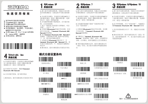
休眠时间设置
语言选择(默认美语)
蜂鸣器
LED指示灯
开始设置 5分
30秒
美语 法语
10分
60秒
德语
20分
2分
扫描仪无休眠模式
常见问题
蓝牙扫描仪与安卓手机连接不上怎么办? 确认手机为android 3.0以上就可以直接连接 为什么部分条码扫描不了? 因为部分不常用的条码在出厂时默认设置是关闭的,您只要开启相应条 码设置就可以正常扫描了,如果您不知道相应条码类型,请联系生产厂商 为什么配对后条码无法上传到电脑或者手机? 1.确认是否已经配对成功,配对成功蓝牙扫描仪LED显示是蓝色 2.是否已经开启了盘点功能(盘点模式下条码不会自动上传,需要手动 扫相应的条码上传) 3.更改为普通模式,即可一边扫描一边上传 电脑或手机搜索不到蓝牙扫描仪怎么办? 1.确认蓝牙扫描仪处于开机状态 2.确认蓝牙扫描仪处于串口模式 3.确认蓝牙扫描仪连接匹配模式是HID模式还是SPP模式 4.蓝牙扫描仪处于HID模式配对连接时,2个蓝色指示灯会闪烁,蓝牙扫 描仪处于SPP模式配对连接时,1个蓝色指示灯闪烁且需要在SPP测试工具 中才能使用 蓝牙扫描仪已经和手机或电脑连接过,怎么再次与该手机或电脑配对? 1.在电脑蓝牙面板中选择已配对的蓝牙扫描仪,点击“删除”按钮 (或在手机蓝牙中取消已配对的蓝牙设备) 2.设置蓝牙扫描仪,使蓝牙扫描仪进入配对状态(有以下两种方式)
免费声明
对于超越我们责任能力范围的自然灾害(如: 地震、水灾等)而导致的损失,本公司不承担 任何责任。 在任何情况下,对于伴随本产品的使用而带来 的任何损失(包括依照手册说明使用而导致的 损失),诸如:公司利润的损失、信誉损失、 营业中断、或存储数据的丢失/改变等,以及因 此导致的任何特别的、意外的、连带的或间接 的损失,本公司不承担任何责任。 对由于不当使用非本公司指定的通讯硬件或软 件而导致的损失,本公司不承担任何责任。 对于通过使用本产品获得的讯息、数据、档案 或其它产品与服务,本公司不提供任何形式的 保证与技术支持,且对于用户对这些讯息、数 据、档案或其它产品与服务的使用,不承担任 何责任。 对于通过本产品使用的第三方软件,本公司不 承担任何形式的担保与技术支持责任。 本手册的内容依照“现状”提供。除非适用法 律另有规定,否则本公司不对本文档的准确性 、可靠性和内容做出任何类型的、明确的或默 许的保证。
ESF-03消费机说明书

FANGKA ESF-03感应卡售饭机使用说明目录机器概述------------------------------------------------------------------------------系统安装------------------------------------------------------------------------------售饭机消费----------------------------------------------------硬件系统功能设置--------------------------------------------------------------------通讯方式--------------------------------------------------------------------------------周边设备--------------------------------------------------------------------------------技术支持--------------------------------------------------------------------------------产品配置详细表--------------------------------------------------------------------------------一、机器概述1.概述ESF-03收费机是以IC感应卡技术为核心的新一代食堂管理设备,方便易用,结合现代管理而设计,具有技术先进、可靠安全、无需维护、投资一步到位等优点,是广大学校、企事业单位提高管理水平,实现电脑作业的最佳选择。
2.机器面板(1)显示屏未操作时显示0元,一段时间未操作则显示时间屏保;(2)指示灯POWER工作电源指示(3)键盘统计:查询累计消费额/记录数功能键取消键确认键1-9数字键(4)刷卡区(在机器最顶端)(7)三针接口为通讯接口,采用RS485通讯方式(8)后备电池开关3.参数外形尺寸:24.5*18.5*13.5 cm工作电压:220V功率:5-8W工作温度:0℃~70℃后备电源:4-6小时通讯方式:RS485存储容量:16000条记录卡片:Mifare1 IC卡读卡距离:5至10厘米二、系统安装系统构成:ESF-03收费机,IC感应卡,发卡器,网卡,网线,计算机,收费管理软件。