Through Synchronized Phasor Measurements, ” Control and Dynamic Systems, vol. 43,
永磁同步电机电压前馈补偿

永磁同步电机电压前馈补偿
永磁同步电机(PMSM)是一种高性能的电动机,广泛应用于工业、汽车和航空航天领域。
然而,PMSM在运行过程中可能会受到电
压波动的影响,导致性能下降和系统稳定性降低。
为了解决这一问题,电压前馈补偿技术被引入到PMSM控制系统中。
电压前馈补偿是一种通过测量电压波动并及时对其进行补偿的
控制技术。
在PMSM系统中,电压前馈补偿可以通过引入一个电压补
偿环节来实现。
这个补偿环节可以根据实时测量的电压波动信息,
及时调整电压输出,使得PMSM系统能够稳定运行并保持高性能。
采用电压前馈补偿技术可以显著提高PMSM系统的性能和稳定性。
通过及时响应电压波动,系统可以更快地调整电压输出,减小电压
波动对PMSM系统的影响。
这不仅可以提高PMSM系统的动态响应能力,还可以降低系统的能耗和维护成本。
总的来说,电压前馈补偿技术为PMSM系统带来了许多优势,包
括提高性能、稳定性和可靠性。
随着这一技术的不断发展和应用,
相信PMSM在各个领域的应用将会得到进一步的推广和发展。
PMU基本介绍全解

PMU的用途
4)分析发电机组的动态特性及安全峪度分析
通过PMU装置高速采集的发电机组励磁电压、励磁电流、气门开度信号、 AGC控制信号、PSS控制信号等,可分析出发电机组的动态调频特性,进行 发电机的安全峪度分析,为分析发电机的动态过程提供依据。监测发电机 进相、欠励、过励等运行工况,异常时报警。绘制发电机运行极限图,根 据实时测量数据确定发电机的运行点,实时计算发电机运行裕度,在异常 运行时告警。
PMU功能应用
(3)同步测量励磁电流/励磁电压,用于分析机组的励磁特性 (4)同步AGC控制信号,用于分析AGC控制响应特性 (5)获取高精度的时间信号
PMU功能应用
2、同步相量数据传输 装置根据通信规约将同步相量数据传输到主站,传输的通道根据实 际情况而定,如:2M/10M/100M/64K/Modem等,传输通信链 路一般采用TCP/IP。 3、就地数据管理及显示 (1)装置的参数当地整定; (2)装置的测量数据可以在计算机界面上显示出来
同步相量测量装置(PMU) 技术介绍
主要内容
一、 PMU及动态监测系统的技术背景 二、同步相量测量基础 三、PMU的功能及作用
第一节 PMU及动态监测系统的技术背景
技术背景
动态监测技术出现的背景
传统的电力系统监测手段主要有侧重于记录电磁暂态过程的各种故 障录波仪和侧重于监测系统稳态运行情况的SCADA系统。 但都存在不足:传统的故障录波器只能记录故障前后几秒的暂态波 形,由于数据量大,难以全天候保存,而且不同地点之间缺乏准确的 共同时间标记,记录数据只是局部有效,难以用于对全系统动态行为 的分析。 SCADA大约提供4秒刷新一次的稳态数据,对电网的动态状 态预测、低频振荡、故障分析等几乎不能提供任何帮助。 因此,电力学术界提出 “同步相量测量理论”和“实时动态监测系 统”来解决这一问题。 在电力系统重要的变电站和发电厂安装同步相量测量装置(PMU), 构建电力系统实时动态监测系统,并通过调度中心分析中心站实现对 电力系统动态过程的监测和分析。该系统将成为电力系统调度中心的 动态实时数据平台的主要数据源,并逐步与SCADA/EMS系统及安全自动 控制系统相结合,以加强对电力系统动态安全稳定的监控。
Phasor Representation - Eastern Regional Load Despatch Centre相量表示东部区域负荷调度中心共43页
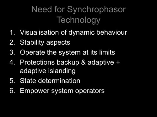
1. Visualisation of dynamic behaviour 2. Stability aspects 3. Operate the system at its limits 4. Protections backup & adaptive +
• LOSS OF DC AND OTHER INTERNAL SELF MONITORING
FEATURES OF A PMU-CONTINUED
• REMOTE COMMUNICATION PORT FOR TCP/IP AND STREAMING DATA IN IEEE1344 OR PC 37.118 SYNCHROPHASOR FORMAT
• 2 SETTABLE LEVELS FOR FREQUENCY AND RATE OF CHANGE OF FREQUENCY
• SETTABLE LEVELS FOR UNDER VOLTAGE & OVERCURRENT PICKUP
• ONE ‘NO’ CONTACT FOR ABNORMAL FREQUENCY, RATE OF CHANGE OF FREQUENCY, UNDERVOLTAGE & OVERCURRENT PICKUP
PHASOR REPRESENTATION
Standards
• The original standard for PMUs, C37.1344, was released in 2019 and was reaffirmed in 2019.
• The new standard IEEE PC37.118 “Standard for Synchrophasors for Power Systems” has now replaced the earlier one.
PCS-996_同步相量测量系统_说明书

南京南瑞继保电气有限公司
iii
PCS-996 同步向量测量系统
在装置电源关闭后,直流回路中仍然可能存在危险的电压。这些电压需在数秒钟后才会消失。 警示! 接地 装置的接地端子必须可靠接地。 运行环境 该装置只允许运行在技术参数所规定的大气环境中,而且运行环境不能存在不正常的震动。 额定值 在接入交流电压电流回路或直流电源回路时,请确认他们符合装置的额定参数。 印刷电路板 在装置带电时,不允许插入或拔出印刷电路板,否则可能导致装置不正确动作。 外部回路
PCS-996 同步相量测量系统 说明书
PCS-996 同步向量测量系统
前言 使用产品前,请仔细阅读本章节!
本章叙述了使用产品前的安全预防建议。在安装和使用时,本章内容必须全部阅读且充分理解。 忽略说明书中相关警示说明,因不当操作造成的任何损害,本公司不承担相应负责。 在对本装置做任何操作前,相关专业人员必须仔细阅读本说明书,熟悉操作相关内容。 操作指导及警告 本手册中将会用到以下指示标记和标准定义: 危险! 意味着如果安全预防措施被忽视,则会导致人员死亡,严重的人身伤害,或
当把装置输出的接点连接到外部回路时,须仔细检查所用的外部电源电压,以防止所连接的回 路过热。 连接电缆 仔细处理连接的电缆避免施加过大的外力。
版权声明
版本: R1.00 P/N: ZL_WPMU5118.1010 Copyright © 2010 NR 南京南瑞继保电气有限公司版权所有 我们对本文档及其中的内容具有全部的知识产权。 除非特别授权, 禁 止复制或向第三方分发。 凡侵犯本公司版权等知识产权的, 本公司必 依法追究其法律责任。 技术支持,请联系: 电话:025-52107703、8008289967、4008289967 传真:025-52100770 或登陆网站:/ser_sup 购买产品,请联系: 电话:025-87178911,传真: 025-52100511、025-52100512 电子信箱:market@
【CN109828469A】相位优化的扩张状态观测器及抗扰控制系统【专利】
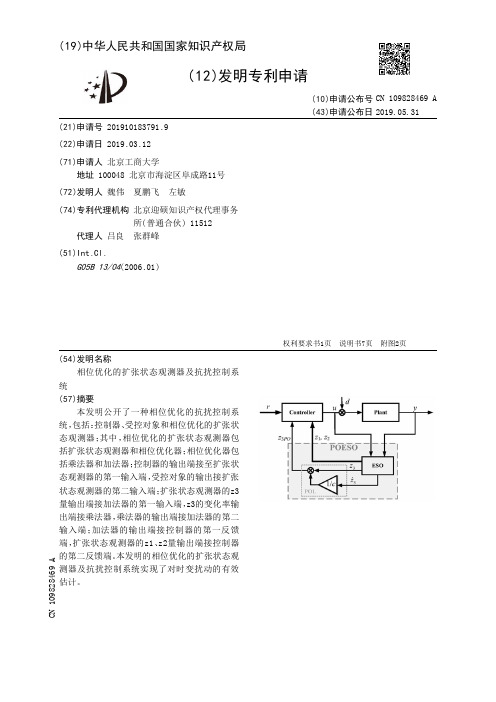
(19)中华人民共和国国家知识产权局(12)发明专利申请(10)申请公布号 (43)申请公布日 (21)申请号 201910183791.9(22)申请日 2019.03.12(71)申请人 北京工商大学地址 100048 北京市海淀区阜成路11号(72)发明人 魏伟 夏鹏飞 左敏 (74)专利代理机构 北京迎硕知识产权代理事务所(普通合伙) 11512代理人 吕良 张群峰(51)Int.Cl.G05B 13/04(2006.01)(54)发明名称相位优化的扩张状态观测器及抗扰控制系统(57)摘要本发明公开了一种相位优化的抗扰控制系统,包括:控制器、受控对象和相位优化的扩张状态观测器;其中,相位优化的扩张状态观测器包括扩张状态观测器和相位优化器;相位优化器包括乘法器和加法器;控制器的输出端接至扩张状态观测器的第一输入端,受控对象的输出接扩张状态观测器的第二输入端;扩张状态观测器的z3量输出端接加法器的第一输入端,z3的变化率输出端接乘法器,乘法器的输出端接加法器的第二输入端;加法器的输出端接控制器的第一反馈端,扩张状态观测器的z1、z2量输出端接控制器的第二反馈端。
本发明的相位优化的扩张状态观测器及抗扰控制系统实现了对时变扰动的有效估计。
权利要求书1页 说明书7页 附图2页CN 109828469 A 2019.05.31C N 109828469A权 利 要 求 书1/1页CN 109828469 A1.一种相位优化的抗扰控制系统,包括:控制器、受控对象和相位优化的扩张状态观测器;其特征在于:相位优化的扩张状态观测器包括扩张状态观测器和相位优化器;相位优化器包括乘法器和加法器;控制器的输出端接至扩张状态观测器的第一输入端,受控对象的输出接扩张状态观测器的第二输入端;扩张状态观测器的z3量输出端接加法器的第一输入端,z3的变化率输出端接乘法器,乘法器的输出端接加法器的第二输入端;加法器的输出端接控制器的第一反馈端,扩张状态观测器的z1、z2量输出端接控制器的第二反馈端。
基于扰动转矩观测器PMSM无位置传感器控制系统
换相成为最近电机控制领域研究的热点[3-4]。 目前针对 PMSM 无位置传感器控制算法主要
有:龙伯格控制算法[5]、卡尔曼控制算法[6]、滑模控 制算法[7]、定子磁链估计器算法[8]等。定子磁链估 计器算法是一种基于电压模型的定子磁链估计
基金项目:国家科技支撑计划资助项目(2015BAA03B01) 作者简介:阴建强(1974—),男,硕士,高级讲师,Email:yh2002h@ 通讯作者:杨沛豪(1993—),男,硕士,工程师,Email:yangpeihao@
为了提高 PMSM 无位置传感器低速控制性 能,文献[9]提出一种基于电流模型的定子磁链估 计器,但是该估计器依赖于转子位置信息,无法实 现全转速范围无传感器控制。文献[10]采用高频 信号注入法提取电机转子位置信息,但是一般控 制系统中没有单独设置电流、电压环,高频电压、 电流信号难以控制,很大程度上影响了控制精度。
Abstract: The sensorless control of PMSM based on control algorithm is a research hotspot in the field of motor control. A PMSM sensorless control system based on low-speed pulse and high-frequency stator flux injection was proposed,and the traditional stator flux estimator was improved and the high-frequency signal was introduced into the low-pass filter to improve the accuracy of the stator flux estimator when the motor is running at low speed. In view of the fact that the sensorless control system is easily affected by torque ripple when PMSM is running at medium and low speed,the disturbance torque observer was used to suppress the voltage error caused by the torque disturbance. The effectiveness and feasibility of the proposed scheme were verified by experiments.
Synchronverter_flyer
Intellectual Property
UK Patent (GB0820699.7) filed in November 2008. Inventors: Dr Qing‐Chang Zhong (University of Liverpool) and Prof. George Weiss (Tel Aviv University).
Application Areas
• Distributed generation and renewable energy, such as combined heat and power (CHP), wind power and solar power. The synchronverter technology allows these sources to take part in the regulation of power system frequency, voltage and overall stability. • Uninterrupted power supplies (UPS), in particular, the parallel operation of multiple UPSs • Isolated/distributed power supplies, e.g. to replace rotary frequency converters • Induction heating • Static synchronous compensator (STATCOM) to improve power factor • HVDC transmission (at the receiving end)
Synchronverters: Inverters that mimic synchronous generators
213402115_考虑谐波耦合的多变流器并网系统建模及交直流谐波交互特性分析
第51卷第10期电力系统保护与控制Vol.51 No.10 2023年5月16日Power System Protection and Control May 16, 2023 DOI: 10.19783/ki.pspc.221314考虑谐波耦合的多变流器并网系统建模及交直流谐波交互特性分析林顺富1,李 寅1,戴烨敏2,杨 帆1,边晓燕1,李东东1(1.上海电力大学电气工程学院,上海 200090;2.国网上海市电力公司青浦供电公司,上海 201799)摘要:新型电力系统中高比例可再生能源和高比例电力电子设备接入的特征带来异于传统电网下的谐波交互问题,多变流器拓扑的谐波耦合交互特性亟待研究。
首先,基于谐波状态空间(harmonic state space, HSS)对多变流器并网系统(multiple grid-connected-converter system, MGCCS)建立考虑谐波耦合的谐波传递函数矩阵模型,综合考虑了系统各控制环节对状态变量的影响以及变流器的级联、并联。
其次,基于所建HSS模型明确定义谐波耦合系数,并用于揭示多变流器拓扑的谐波耦合机理,分析级联、并联变流器谐波交互特性。
然后,应用谐波耦合系数量化分析MGCCS中滤波电感、电流环、锁相环等关键参数对系统谐波交互的影响。
最后,将HSS模型和Matlab/Simulink 模型、RT-LAB模型的结果进行对比,验证了所建HSS模型的精确性,以及谐波耦合系数理论应用于系统交直流谐波交互分析的有效性。
关键词:多变流器并网系统;交直流谐波交互;谐波状态空间;谐波耦合系数;并网电流Modeling of a multiple grid-connected-converter system considering harmonic coupling andanalysis of AC/DC harmonic interaction characteristicsLIN Shunfu1, LI Yin1, DAI Yemin2, YANG Fan1, BIAN Xiaoyan1, LI Dongdong1(1. College of Electrical Engineering, Shanghai University of Electric Power, Shanghai 200090, China; 2. Qingpu PowerSupply Company of State Grid Shanghai Municipal Electric Power Company, Shanghai 201799, China) Abstract: The characteristics of high penetration of renewable energy and high proportion of power electronic equipment in new power systems bring a harmonic interaction problem. This is different from traditional power systems. The harmonic coupling interaction characteristics of the multi-converter topology need to be studied. First, based on the harmonic state space (HSS), the harmonic transfer function matrix model considering harmonic coupling is established for the multiple grid-connected-converter system (MGCCS). The model comprehensively considers the influence of each control link of the system on the state variables as well as the factors of cascade and parallel converters. Second, the harmonic coupling coefficient is defined based on the established HSS model. This is used to reveal the harmonic coupling mechanism of the multi-converter topology, and analyze the harmonic interaction characteristics of the cascade and parallel converters. Then, the harmonic coupling coefficient is used to quantify the influence of key parameters such as filter inductor, current loop and phase-locked loop on the harmonic interaction of MGCCS. Finally, the results of the HSS model, Matlab/Simulink model and RT-LAB model are compared to verify the accuracy of the proposed HSS model and the effectiveness of the harmonic coupling coefficient theory applied to the AC/DC harmonic interaction analysis of the system.This work is supported by the National Natural Science Foundation of China (No. 51977127).Key words: multiple grid-connected-converter system; AC/DC harmonic interaction; harmonic state space;harmonic coupling coefficient; grid-connected current0 引言在“双碳”目标的背景下,以高渗透率的可再基金项目:国家自然科学基金项目资助(51977127);上海市科学技术委员会项目资助(19020500800);上海市教育发展基金会和上海市教育委员会“曙光计划”项目资助(20SG52) 生能源、高比例的电力电子设备、高速增长的新型负荷为主要特征的新型电力系统逐步形成[1-4]。
美国IMS电机—HYbird技术的介绍
From the market leader in integrated motion control and the MDrive ® platform comesmotion technology TMServo and Stepper — these two motion technologies have been very prominent in the motion control in-dustry for decades. Traditionally, both systems have their advantages and disadvantages when applied to motion applications, including:Servo technology —Advantages1. Capable of supplying peak torque2. Can deliver signifi cant torque at higher speeds3. Continuous closed loopDisadvantages1. Need for PID tuning2. Error driven3. Higher complexity4. Higher price point5. Servos have inherent dither -slight shaft oscillations atposition6. PotentialinstabilityStepper technology —Advantages1. High torque at low speed(may eliminate need for gearbox)2. Shaft stiffness at standstill3. No tuning4. Cost effectiveDisadvantages1. Threat of loss of motor synchronization or stall2. Must size with up to a 50% torque margin3. Constant torque and current device4. Excessive heating5. Resonant zones -dependent on system to which mountedThe gap between stepper and servo technologies.Historically, the advantages and disadvantagesof both servo and stepper systems have drawn a rather clear line as to when one or the other is ap-plied. Most design engineers have justifi cations for a preferred motion platform. Engineers may have used a technology in the past and developed their opinion based on a positive or negative experience. Servo system manufacturers have tried to domi-nate the motion arena while placing doubts among would-be users of anything other than servo, and they have had a good measure of success.Many manufacturers abandoned further product development of stepper motor based systems for which Intelligent Motion Systems (IMS), now IMS Schneider Electric Motion USA, has benefi ted over the last 15 years. This has allowed IMS SEM to gain signifi cant market share and, through a continued commitment to stepper motor control technology, emerge as the innovation market leader with the MDrive®integrated platform of products.With the introduction of the MDrive integrated plat-form in 2001, and since having sold over ½ million of these products worldwide, IMS SEM solidifi ed its leadership position in integrated motion control and continues to be recognized as the innovation leader in stepper motor control systems.Today, IMS SEM continues our commitment to innovation by introducing another new patented motor control technology:Hybrid Motion Technology™.Servo and Stepper TechnologiesHybrid TechnologyHybrid Motion Technology™ more than fi lls the gap between servo and stepper motor technologies.These bene fi ts include: • Variable current / torque • Real time control• Optimum torque at all speeds • Stiffness as standstill • No tuning• Cost effectiveHybrid Motion Technology™ also greatly expands the application range of stepper based motion control to include:• Web tensioning • Clamping • Roll feeders• Force applications – requiring torque mode • Conveyors • Rotary knife • Pick and place– unaffected by tansient loadingWhat does Hybrid Motion Technology ™ mean to the design engineer?1. A compelling alternative for demanding motion applications2. Reduced system cost3. Reduced complexityIMS SEM recognized a gap between stepper and servo technologies, and addressed this by creating a new motion control technology. This new technol-ogy delivers the bene fi ts of both servo and stepper motor technologies, with unique capabilities and enhancements over both.Because the industry needs a clear de fi nition and way to have deliberate discussion as to its applica-tion, this new technology required a name. And, being the innovation leader in stepper motor based control systems, we believe we have the inertia within the industry to coin the term for this new category of motion control.So we recommend this new technology be referred to generically as “hybrid”, within the context of motion control, as the best intuitive reference.So, now we have:• Stepper • Servo• HybridAnd IMS SEM has trademarked our version of this new motion control category:• Hybrid Motion Technology ™As you can see in the fi gure below, Hybrid MotionTechnology™ not only eliminates many drawbacks of stepper and servo systems, it introduces bene fits.For2+ yearsHybrid Motion Technology™has been solving demanding applications for customers.MDrive® motor+driver with Hybrid Motion Technology™low cost integrated solutions where brushless motion is required Environmentally friendly energysavingvariable current control feature reduces electrical power consumptionHybrid Motion Technology™ changing the rules of motor control preventing the loss of synchronization due to transient or continued overload, extreme accel-eration or deceleration, or excessive slew speed when applied to stepper motors Hybrid Motion Technology™ is available in industry leading MDrive® motor+driver products. These integrated motion systems solve many servo applications with a compact, low cost stepper solution.MDrive Hybrid motion systems combine a fl exible operating environment and long list of features, offering clear advantages in a cost effective package for a wide range of motion control applications such as: web tensioning, conveyors, bottle capping, medical automation, clamping, feeders, cut-to-length, package sorter, pick and place, and form, fi ll and seal.MDrive Hybrid motion systems are available in NEMA motor sizes 17, 23 and 34. System versions include:Step • Torque • SpeedA stepper motor integrated with microstepping drive and internal encoder features three (3) HMT operating modes – Step, Torque and Speed. Programming is via a GUI provided.Motion ControlA fully programmable motion controller integrated with a stepper motor, microstepping drive and internal encoder. MDrive Hybrid Motion Control systems communicate via RS-422/485 or Ethernet. CANopen products are also available. MDrive ®H ybrid with Hybrid Motion Technology™Motion systems with Hybrid Motion Technology™motion technology TM© Schneider Electric Motion USA All Rights Reserved. REV100610。
粒子影像测速(PIV)技术概述
粒子影像测速(PIV)技术概述1.PIV技术介绍1.1.引言目前为止,人类对流体力学仍有许多疑难问题,如对湍流、非定常流动等现象了解甚少,而在许多工程应用如飞行器外形设计、内燃机燃烧室中的多相流动等中又迫切需要解决这些问题,因而使流场测量问题变得极为重要。
流场测速新方法研究中,至今已发展了激光多普勒测速LDV(Laser Doppler Velocimetry)、粒子影像测速PIV(Particle Image Velocimetry)等技术。
LDV的综合性能较高,具有高精度、高分辨率和非接触测量等优点,通常作为仪器标校技术使用,但LDV只能实现单点测量。
PIV技术是一种全场、动态、非接触测量手段,已获得广泛使用,成功应用于风洞、水洞、水槽燃烧及喷射等实验中。
PIV研究始于上个世纪80年代,随着光学和计算机图像处理技术的迅猛发展,PIV取得了长足进步,测量精度已与LDV接近。
1.2.PIV原理图1是PIV 技术应用的简单原理图。
散播在流场中的跟随性及反光性良好的示踪粒子,由激光光束首先入射到一组球面透镜上,经聚焦后通过全反射镜至一组可调的柱面透镜形成具有一定厚度的片光,照亮流场中特定的区域,此时经过此区域的示踪粒子被照亮,通过CCD(CMOS)成像设备进行成像。
对这个特定的区域在一定时间间隔内利用图1 PIV简单原理图激光脉冲连续照亮两次,就能得到粒子在第一次照亮时间t 和第二次照亮时间t’的两个图像,对这两幅图像进行互相关分析,就能得到流场内部的二维速度矢量分布。
在利用PIV 技术测量流速时,需要在二维流场中均匀散布跟随性、反光性良好且比重与流体相当的示踪粒子。
将激光器产生的光束经透镜散射后形成厚度约1 mm 的片光源入射到流场待测区域,CCD 摄像机以垂直片光源的方向对准该区域。
利用示踪粒子对光的散射作用,记录下两次脉冲激光曝光时粒子的图像,形成两幅PIV 底片(即一对相同待测区域、不同时刻的图片) ,底片上记录的是整个待测区域的粒子图像。
- 1、下载文档前请自行甄别文档内容的完整性,平台不提供额外的编辑、内容补充、找答案等附加服务。
- 2、"仅部分预览"的文档,不可在线预览部分如存在完整性等问题,可反馈申请退款(可完整预览的文档不适用该条件!)。
- 3、如文档侵犯您的权益,请联系客服反馈,我们会尽快为您处理(人工客服工作时间:9:00-18:30)。
REFERENCES
[1]IEEE Power Engineering Society System Oscillations Working Group. “Inter-AreaOscillations in Power Systems,” IEEE #95-TP-101, October 1994.
[2]A.G. Phadke and J.S. Thorp. “Improved Control and Protection of Power SystemsThrough Synchronized Phasor Measurements,” Control and Dynamic Systems, vol. 43,Academic Press, 1991, pp. 335-376.
[3]Macrodyne, Inc. “Phasor Measurement Unit-Model 1690,” Application and PerformanceData Sheet, 1993.
[4]O. Faucon and Y. Therpe. "Power System Control Scheme Based on Phase AngleMeasurements," Precise Measurements in Power Systems Conference sponsored by TheNational Science Foundation and Virginia Tech, Arlington, Virginia, October 27-29,1993.
[5]Y. Ohura, M. Suzuki, K. Yanagihashi, M. Yamamura, K. Omata, T. Nakamura, S.Mitamura and H. Watanabe. “A Predictive Out-of-Step Protection System Based onObservation of the Phase Difference Between Substations,” IEEE Transactions on PowerDelivery, vol. 5, no. 4, November 1990, pp. 1695-1702.
[6]K. Matasuzawa, K. Yanagihashi, J. Tsukita, M. Sato, T. Nakamura, and A. Takeuchi,“Stabilizing Control System Preventing Loss of Synchronism From Extension and ItsActual Operating Experience,” IEEE-PES Winter Meeting, 95WM 188-3 PWRS, January1995.
[7]I.W. Slutsker, S. Mokhtari, L.A. Jaques, J.M. Gonzalez Provost, M. Baena Perez, J.Benaventa Sierra, F. Gonzalez Gonzalez and J.M. Montes Figueroa. "Implementation ofPhasor Measurements in State Estimator at Sevillana de Electricidad," Proceedings of theIEEE-PICA Conference, Salt Lake City, Utah, May 7-12, 1995, pp. 392-398.
[8]M.A. Smith. "Improved Dynamic Stability Using FACTS Devices With PhasorMeasurement Feedback," Master's Thesis, Virginia Polytechnic Institute and StateUniversity, December 1994.[9]A.F. Snyder. “Application of Phasor Measurements to Power System Control,”Preliminary Research Report, Laboratoire d’Electrotechnique de Grenoble, Grenoble,France, December 1995.
[10]A.F. Snyder. “Application of Phasor Measurements to Power System Control:Supplementary Information,” Interim Research Report, Electricité de France, Clamart,France, April 1996.
[11]P. Kundur. Power System Control and Stability, New York: McGraw-Hill, Inc., 1994, pp.3-168, 699-825 and 1103-1166.
[12]The Institute of Electrical and Electronics Engineers. “Eigenanalysis and FrequencyDomain Methods for System Dynamic Performance,” IEEE #90TH0292-3-PWR, 1989.
[13]B.C. Kuo. Automatic Control Systems, 5th Ed., New Jersey: Prentice-Hall, Inc., 1987, pp.185-187 and 384-459.
[14]IEEE-PES and CIGRE. “Facts Overview,” IEEE Cat. #95TP108, 1995.[15]CIGRE Working Group 32-03, “Tentative Classification and Terminologies Relating toStability Problems of Power Systems,” Electra, No. 56, 1978.
[16]IEEE Task Force, “Proposed Terms and Definitions for Power System Stability,” IEEETransactions, vol. PAS-101, pp. 1894-1898, July 1982.
[17]G.C. Verghese, I.J. Perez-Arriaga and F.C. Schweppe, “Selective Modal Analysis withApplication to Electric Power Systems, Part I: Heuristic Introduction, Part II: TheDynamic Stability Problem,” IEEE Transactions, vol. PAS-101, no. 9, pp. 3117-3134,September 1982.
[18]D.R. Ostojic. “Identification of Optimum Site for Power System Stabiliser Applications,”IEE Proceedings, vol. 135, pt. C, no. 5, September 1988, pp. 416-419.
[19]D.R. Ostojic. “Stabilization of Multimodal Electromechanical Oscillations by CoordinatedApplication of Power System Stabilizers,” IEEE Transactions on Power Systems, vol. 6,no. 4, November 1991, pp. 1439-1445.
[20]X. Yang and A. Feliachi. “Stabilization of Inter-Area Oscillation Modes ThroughExcitation Systems,” IEEE Transactions on Power Systems, vol. 9, no. 1, February 1994,pp. 494-502.[21]X. Yang, A. Feliachi and R. Adapa. “Damping Enhancement in the Western U.S. PowerSystem, A Case Study,” IEEE Transactions on Power Systems, vol. 10, no. 2, August1995, pp. 1271-1278.
[22]M.E. About-Ela, A.A. Sallam, J.D. McCalley and A.A. Fouad. “Damping ControllerDesign for Power System Oscillations Using Global Signals,” IEEE Transactions onPower Systems, vol. 11, no. 2, May 1996, pp. 767-773.
[23]E.V. Larsen and D.A. Swann. “Applying Power System Stabilizers Part I: GeneralConcepts,” IEEE Transactions on Power Apparatus and Systems, vol. PAS-100, no. 6,June 1981, pp. 3017-3024.
[24]E.V. Larsen and D.A. Swann. “Applying Power System Stabilizers Part II: PerformanceObjectives and Tuning Concepts,” IEEE Transactions on Power Apparatus and Systems,vol. PAS-100, no. 6, June 1981, pp. 3025-3033.