CH 02-放大器及
音响放大器 课程设计
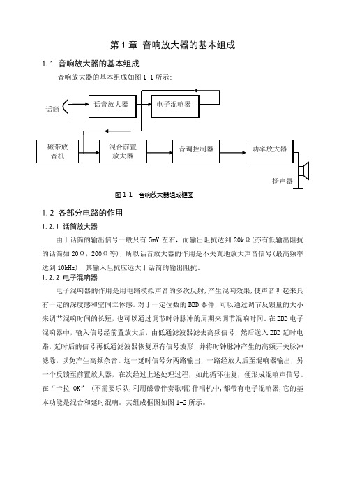
第1章音响放大器的基本组成1.1 音响放大器的基本组成音响放大器的基本组成如图1-1所示:1.2 各部分电路的作用1.2.1 话筒放大器由于话筒的输出信号一般只有5mV左右,而输出阻抗达到20kΩ(亦有低输出阻抗的话筒如20Ω,200Ω等),所以话音放大器的作用是不失真地放大声音信号(最高频率达到10kHz),其输入阻抗应远大于话筒的输出阻抗。
1.2.2 电子混响器电子混响器的作用是用电路模拟声音的多次反射,产生混响效果,使声音听起来具有一定的深度感和空间立体感。
对于一定位数的BBD器件,可以通过调节反馈量的大小来调节混响时间的长短,也可以通过调节时钟脉冲的周期来调节混响时间。
在BBD电子混响器中,输入信号经前置放大后,由低通滤波器滤去高频信号,然后送入BBD延时电路,延时后的信号再低通滤波器恢复原有信号波形,并将时钟脉冲产生的高频开关脉冲滤除,以免产生高频杂音。
这一延时信号分两路输出,一路经放大后至混响器输出,另一个反馈至前置放大器,在次经过上述处理过程,如此循环往复,便形成混响声信号。
在“卡拉OK” (不需要乐队,利用磁带伴奏歌唱)伴唱机中,都带有电子混响器,它的基本功能是混合和延时混响。
其组成框图如图1-2所示。
图1-2 电子混响器组成框图图中,集成电路BBD 称为模拟延时器,其内部有由场效应管构成的多级电子开关和高精度存储器。
在外加时钟脉冲作用下,这些电子开关不断地接通和断开,对输入信号进行取样。
保持并向后级传递,从而使BBD 的输出信号相对于输入信号延迟乐一段时间。
BBD 的级数越多,时钟脉冲的频率越高,延迟时间越长。
BBD 配有专用时钟电路,如MN3102时钟电路与MN3200系列的BBD 配套。
电子混响器的实验电路图所示(附录一),其中两级二阶低通滤波器(MFB)A 1、A 2滤去4kHz(语音)以上的高频成分,反相器A 3用于 隔离混响器的输出与输入级间的相互影响。
RP 1调节混响器的输入电压,RP 2调节 MN3207的平衡输出以减少失真,RP 3控制延时时间,RP 4控制混响器的输出电压。
2.3采样保持器

•
•
•
•
•
•
•
•
捕捉时间不影响采样精度,但对采样频率的提高有影响。如果采样/
保持器在保持状态时的输出为-FSR,而在保持状态结束时输入已变至
+FSR,则以保持状态转至跟踪状态采样/保持器所需的捕捉时间最长,
产品手册上给出的tAC就是指这种状态的值。
使用采样/保持器后,系统能对频率不高于12.44kHz
正的信号进行采样,使系统可采集的信号频率提高了
许多倍,大大改善了系统的采样速率。
由采样定理可知,一个有限带宽的模拟信
号是可以在某个采样频率下重新恢复而不丧失
任何信息的,该采样频率至少应两倍于最高信
号频率。这意味着带采样/保持器的数据采集
系统必须在速率至少为两倍的信号频率下采样、
知的捕捉时间tAC=6μs,孔径时间tAP=50ns,
ADC0804的转换时间conv=100μs(时钟频率
为640kHz),计算系统可采集的最高输入信
号频率。
• AD582
• 解:tAP与tAC和tCONV相比,可以忽略。
根据式(5—7)可知
fmax=1/2(tAC+tCONV)=1/2*(6*106+100*10-6)=4.72*103(Hz)
• •设保持电容原先的保持电压为+5V,当由保持
状态转为跟踪状态时,采样/保持器输入电压
为-5V。
• 经过一段时间跟踪,电容器电压变为-5V,然
后又转为保持状态。这时,电容器电压会逐渐
向+5V方向变动,使保持电压发生变动,从而
产生误差。
符合高精度要求的电容器
脑磁图兼容DC脑电图设备

脑磁图兼容DC脑电图设备一、技术参数及要求:1.通道:64ch放大器,放大器后期可以直接升级为96导、128导等。
2.★放大器可直接拆分为2套32导放大器进行使用。
3.可精确采集脑电图(EEG)、肌电图(EMG)、眼电图(EOG)及诱发电位。
4.电极帽:高纯度Ag/AgCl电极,导电介质为膏状不易挥发,须维持1.5-3小时稳定信号。
5.输入阻抗:10/10000 MOhm。
6.共模抑制比:≥ 110 dB。
7.采样率:≥ 4500 Hz同时采集。
8.信号噪声:2µVpp。
9.带宽:DC-900Hz。
10.高通滤波[HZ]:0.016HZ/10S AC或DC可调。
11.低通滤波[HZ]:1000/250可调。
12.★电源:可充电电池供电,避免市电干扰;电池为可更换设计,方便客户自行更换,电池连续供电时间不低于18小时。
13.数据传输介质:双轴光纤。
14.系统支持与主流TMS产品同步采集,放大器不会出现过饱和现象,需提供证明资料。
15.★系统支持与主流脑磁图设备同步采集。
16.零场光学磁力计模块,通过检测生物磁性,结合脑电分析仪用于大脑电磁协同记录。
须满足以下技术要求。
16.1.★灵敏度(宽频噪声能量谱):1-100Hz范围<15fT/√Hz。
16.2.动态范围:±5 nT。
16.3.工作环境要求:静磁场低于50nT。
16.4.探测方向:Y轴,Z轴或者YZ轴同时记录。
16.5.信号输出:模拟信号或USB数字信号。
16.6.探测器尺寸:13x19x110 mm (探头);3.1×11.0x16.5 cm (电子设备)。
16.7.信号线长度:6.5m。
16.8.功耗:5W。
16.9.包含自动控制及数据采集软件,软件需要windows 7 64-bit或以上的计算机。
17.为方便携带,放大器与电源重量不能超过2kg。
18.设备硬件及电极系统通过CE认证,电磁兼容性认证并提供证明资料。
音响放大器主要技术指标及测试方法
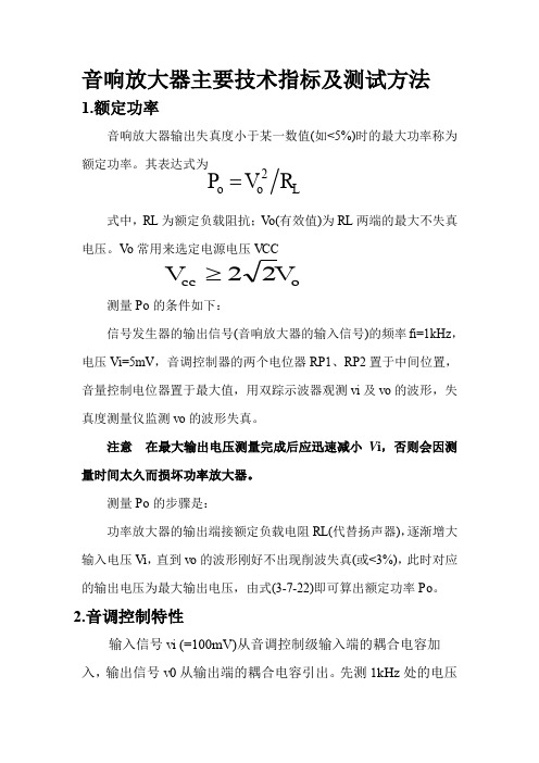
1.额定功率
音响放大器输出失真度小于某一数值(如<5%)时的最大功率称为 额定功率。其表达式为
Po Vo2 RL
式中,RL 为额定负载阻抗;Vo(有效值)为 RL 两端的最大不失真 电压。Vo 常用来选定电源电压 VCC
Vcc 2 2Vo
测量 Po 的条件如下: 信号发生器的输出信号(音响放大器的输入信号)的频率 fi=1kHz, 电压 Vi=5mV,音调控制器的两个电位器 RP1、RP2 置于中间位置, 音量控制电位器置于最大值,用双踪示波器观测 vi 及 vo 的波形,失 真度测量仪监测 vo 的波形失真。 注意 在最大输出电压测量完成后应迅速减小 Vi,否则会因测
整机电路图
R12 75k R11 C12 10k 1F 话筒
+
+9V 2 10k
+
- A1
4 11
1
+
C13 10F
+
C14 10F 电子混响器
C11
3 + 10k
10F
1 LM324 4
RP11 10k
R31 47k R22 30k
+
RP31 470k
R32 47k C32 0.01F +9V C42 +9V 9 - A3 11 4 C35 10F
3.频率响应
放大器的电压增益相对于中音频 fo(1kHz)的电压增益下降 3dB 时对应低音频截止频率 fL 和高音频截止频率 fH,称 fL ~ fH 为放大器的频率响应。 测量条件同上,调节 RP3 使输出电压约为最大输出电压的 50%。 测量步骤是: 音响放大器的输入端接 vi (等于 5mV),RP1 和 RP2 置于最左 端,使信号发生器的输出频率 fi 从 20Hz 至 50kHz 变化(保持 vi=5mV 不变),测出负载电阻 RL 上对应的输出电压 Vo,用半对 数坐标纸绘出频率响应曲线,并在曲线上标注 fL 与 fH 值。
华中科技大学《模拟电子技术基础》——CH01-1省公开课一等奖全国示范课微课金奖PPT课件
绝大部分电路使用 电压恒定,电流随负载改变
电流源
电路中恒流用
不能成为电路系统电源
18/7118
模拟电子电源表示: 电源在哪里?
图二
图一
图三
电源省略
19/71
电源是什么样:
20/71
模拟电路电源大小:
直流电压源:5V,±5V, ±12V ,±15V 直流电压源:1.8V,2.7V, 3.3V , 特点:弱电
2/71 2
1.0 引言
我们生存自然界中存在大量物理量
温度 电量
压力 重量
光亮 流量
声音 风速 XX
速度 液位 XX
位移 转速 XX
3/71 3
1.0 引言
物理量改变就是信息
IT是什么?
信息技术
问题:怎样获取这些物理量改变?
传感器
4/71 4
1.0 引言
传感器怎样反应物理量改变?
温度 重量 压力 流量 光亮 液位 速度 转速 位移 XX 电压 XX
48/7148
1.4.3 放大电路模型类型
AS
Vo VS
AVO
RL Ro RL
Ri Rs Ri
源电压放大倍数是对信号纯放大,应该尽可能确保
信号源电阻会消耗一部分信号源电压造成开环放大倍数降低 为降低开环放大倍数降低,输入电阻应尽可能大
输出电阻会消耗一部分输出电压造成开环放大倍数降低 为降低开环放大倍数降低,输入电阻应尽可能小
模拟电路电源对电路电位限制:
普通情况下,电路中各点电位不会超出电源电压
21/71
放大器
信号源
电源 放大器
负载
n模电关键 n为何要放大? n什么是放大? n对放大有什么要求? n怎样满足对放大要求? n什么器件能够进行放大? n怎样组成放大系统?
bj-au88+ 数码立体声二合一卡拉OK功率放大器 使用说明书

Thank you for purchasing our Wireless Karaoke AV Amplifire .Please read the owner's manual thoroughly prior to use.Please keep the manual for future reference.感谢您购买本公司的数码立体声二合一卡拉OK功率放大器。
为了尽快的熟悉掌握本产品的各项功能,使用前请仔细阅读本说明书。
阅读后,请注意妥善保管。
数码立体声二合一卡拉OK功率放大器WIRELESS KARAOKE AV AMPLIFIERFront PanelHOW TO CONNECT ANY TROUBLES ?65522CAUTION FOR SAFETY FUNCTION AND NAME SPECIFICATIONS CONTENTSThis "Caution for safety" shows various kinds of pictures in order to be used safely and correctly and to prevent from damaging other people, and their property. Please read with full understanding, and carefulness.CAUTION FOR SAFETYFUNCTION AND NAME12345786Music VolumeMusic Tone Control VolumesMicrophone Master Volume Microphone VolumeMicrophone InputPush switch button-"On", and Re-push it and then "Off".To adjust Music Volume.To adjust Tone of Bass, Midrange, and Treble.To adjust Sound Level of Left and Right channels.To adjust Sound Level of all Microphones.To adjust Sound Volume of MIC 1, MIC 2/A and MIC 3/W Microphones (W: Wireless Microphone) .To Input 3 Microphones (MIC 1, MIC 2 and MIC 3).Power Switch Balance VolumeDisplay1113141512Echo Tone Control Volumes To adjust Tone of Bass, Midrange, and Treble.13452LEVEL (Echo)Echo DelayTo adjust Music Interval tone Level.To adjust Volume of Microphone Echo.To adjust Delay Duration of Echo.To adjust Repeat Volume of Echo.Key Control ButtonEcho Repeat16SD CARDTo insert card memory.17USBTo insert USB memory.18: Reverse.: To play back / Recording (Push the button formore than 2 Second): Fast forwarding.REAR PANELVOD and AUX. Audio Input Terminal connectionOptical and Coaxial.Digital Audio Input To adjust volume of Input. Input LevelHDMI 1. HDMI 2HDMI Input6Connect with TV. (Video 1, Video 2) HDMI Output8High Level, Low Level (-11dB) Mic Output (Vocal output)9Connect with Power amplifier. Pre Output7MIC AMic Input 10Connect with Powered sub woofer.Sub woofer Output 11A or B: 4 Ohms - 8 Ohms, A+B: 8 Ohms - 16 Ohms. Speaker Output13It can be connected with other IR receiver.REMOTE Terminal♭: To slow interval tone. # : To fast interval tone. ♮: Back to original.19Wireless microhone indicatorIt lights up at a wireless microphone (A, B) switch ON .Power Cord Socket.Power input AC 220 - 240V / 50Hz.910To adjust Tone for Bass, Midrange and Treble.When pushing button, Input Signal is changedfrom VOD, AUX, Optical, Coaxial, HDMI 1, HDMI 2,Blue tooth, USB/SD card.Microphone Tone Control Volumes Input Select Button12Connect with antenna.Wireless ANT/ RECREMOTE CONTROLLER4HDMI Input ButtonHDMI 1, HDMI 2.1LOUD (Loudness)8: Reverse.: To play back / Recording (Push the button for more than 2 Second): Fast forwarding.2Mute Button 3Input Button6Mic VolumeTo adjust Microphone Volume.7To adjust Music Interval tone Level.♭: To slow interval tone. # : To fast interval tone. ♮: Back to original.Key Control ButtonWhen pushing button,It will be a more dynamic sound.You can select the Input Signals. VOD, AUX, Optical, Coaxial, USB, BT.RepeatDEL: deleteWIRELESS MICROPHONE5Music VolumeTo adjust Music Volume.Channel indication Battery level indicationB A How to set Channel (Frequency)1. Put a microphone to near the front panel of amplifier.2. Set a channel with pushing microphone switch button .3. Channel is set automatically.MIC A: 00 - 18 CH MIC B: 21 - 39 CH/ RECHOW TO CONNECT● The power amplifier switch is not ON.● Remote control batteries is not in.● Batteries ran down.● Echo volume is minimum.Without echo.Can not use remote control.● Adjust the Echo volume.● Turn ON the power amplifier.● Check batteries.● Change batteries to new ones.Any troubles? please check the followings. Your careless mistakes may cause troubles.Consult with your dealers in case any troubles can not be solved after checking the followings.Can not power ON .● The power cord is not connected.● Connect the power cord to AC outlet.Power ON, but no sound.No sound at beginning of the music when switched ON.● Music volume control or Mic. volume control may be set to minimum position.● Music signal choice is incorrect.● The output cords is not connected correctly.● The power amplifier switch is not ON.● Output level of audio component is set to minimum.● Microphone switch is to "OFF".● The microphone cord broken.● Microphone plug is not connected.No microphone sound but playback the music sound.● Set it to "ON".● Repair or replace it.● Connect it correctly.● Adjust it to suitable position.● Adjust for proper sound position.● Choose correct music signal input.● Connect the output cord correctly.● Turn ON the power amplifier.TroubleCauseRemedyANY TROUBLES?Wireless microphone can not switch ON.● Receiver volume is set “ Minimum ” position?● Obstacle wave is disturbing?● Turn up Receiver volume.● Set another channel.● Connect it correctly once again.● Change HDMI cord to new ones.● Is a battery included?● Batteries ran down.● Please put a battery in.● Change batteries to new ones.Noize out of microphoneNo sound and no video at a HDMI connection. ● A connection of a HDMI cord is loose.● The HDMI cord broken.SPECIFICATIONSWireless MicrophoneModulation ModeSignal ReceptionRF Frequency RangeSwitching BandwidthAvailable ChannelsMax Working DistanceRF Output PowerFrequency StabilityS/N RatioTotal Harmonic DistortionAF Freqency ResponseMIC SensitivityReceiver SensitivityPower supply, OthersPower VoltagePower consumptionDimensions (W X H X D)WeightAccessoriesOwner's manualPower CableRemote ControllerWireless MicrophoneWireless Antenapi/4 DQPSK, digitally modulating pi/4 DQPSK, digitally receiving 635-695MHz 300 KHz 38 CH (MIC-A: 0 -18 CH, MIC-B: 21 - 38CH)30m 10mW ±20ppm 96dB 0.5% (max)30Hz - 18Khz, ±2dB -51dBV -95dBm AC220V - 240V / 50Hz 500W 430 X 148 X 327 mm 13.0 Kg 111(MIC-A, MIC-B) 21● Design and specifications subject to change without notice.Max output power Total Harmonic Distortion S/N RatioSpeaker ImpedanceAudio Input VOD, AUX, Optical, Coaxial MIC InputMIC-1, MIC-2/A, MIC-3MIC Output High Level Low LevelPre-amplifier Output Sub woofer Output Frequency response Microphone MusicTone control Music Bass Music Midrange Music TrebleMicrophone Bass Microphone Midrange Microphone Treble Echo Bass Echo Midrange Echo Treble Key ControlHDMI Input (HDMI-1, HDMI-2)HDMI Output USB Input SD Card Input240W + 240W /8Ω350W + 350W /4Ω 0.08% (max)87dB4 - 8Ω (A or B)8 -16Ω (A + B)200mV 20mV 3V 100mV5V 5V20Hz ~20KHz±3dB 20Hz ~20KHz±3dB ±8dB (100Hz)±7dB ( 1KHz)±8dB (10KHz)±8dB (100Hz)±7dB ( 1KHz)±8dB (10KHz)±3dB (100Hz)±3dB ( 1KHz)±3dB (10KHz)13 steps±2.5 pitchType A x 2 pcs Type A x 1 pc1 pc 1 pc327( mm )11101077各部分的功能及名称连接方法故障分析处理安全注意事项安全注意事项是为了安全正确使用本商品、 防止给自己及他人带来财产损害。
电路分析(第3版)-胡翔骏ch05
p u1 i1 u 2 i 2 nu 2 i1 u 2 ni1 0
此式说明,从初级进入理想变压器的功率,全部传输 到次级的负载中,它本身既不消耗,也不储存能量。
10
楚雄师范学院 自兴发
§5-1
电阻为n2R。
理想变压器
2 .当理想变压器次级端接一个电阻 R 时,初级的输入
图5-2
8
楚雄师范学院 自兴发
§5-1
理想变压器
• 表征理想变压器端口特性的 VCR 方程是两个线性代数方
程,因而理想变压器是一种线性双口电阻元件。正如二端 线性电阻元件不同于实际电阻器,理想变压器这种电路元 件也不同于各种实际变压器。例如用线圈绕制的铁心变压 器对电压、电流的工作频率有一定限制,而理想变压器则 是一种理想化模型。它既可工作于交流又可工作于直流, 对电压、电流的频率和波形没有任何限制。
将跟随输入电压uin的变化,故称为电压跟随器。
运放工作在直流和低频信号的条件下,其输出电压与
差模输入电压的典型转移特性曲线uo=f(ud)如图所示。该曲 线有三个明显的特点: 1.uo和ud有不同的比例尺度:uo用V; ud用mV。
图5-8
20
楚雄师范学院 自兴发
§5-2
运算放大器的电路模型
2. 在输入信号很小(|ud|<)的区域内,曲线近似于一条
28
楚雄师范学院 自兴发
§5-2
运算放大器的电路模型
三、理想运算放大器模型 实际运放的开环电压增益非常大(A=105~108),可以近似 认为A=和=0。此时,有限增益运放模型可以进一步简化为 理想运放模型。理想运放模型的符号如图(a)所示,其转移
特性曲线如图(b)所示。
图5-11
一线通说明书
一线通(共缆)设备说明书一线通(共缆)介绍OURCOM奥康一线通(共缆)监控设备是专门针对视频监控而研发生产的,它利用可靠的有线电视网络传输技术来进行视频监控信号的传输。
OURCOM奥康一线通(共缆)监控系统具有抗干扰能力强、传输距离远、布线容易、价格低廉等许多优点。
采用一线通(共缆)监控的传输设备,可以将多路监控信号远传到几公里甚至更远,而且,传输图像的质量可以与光端机媲美,图像质量可达到4级以上,其明显的优势:1)传输距离远、传输质量高由于在OURCOM奥康一线通(共缆)发射器中采用了先进的处理中频处理、上变频技术,极好地补偿了高频同轴电缆对视频信号幅度的衰减以及不同频率间的衰减差,保持了原始图像的亮度和色彩以及实时性,在传输距离达到几公里或更远时,图像信号基本无失真。
若采用中继高频放大的方式传输距离会达到几十公里。
2)布线简单、线缆利用率高一条同轴电缆可传送十多路监控信号。
布线组合不拘一格,可以采用总线、树型、星型多种结构将多点图像、控制集成一根电缆总线双向传输。
一线通(共缆)监控传输系统充分利用线缆资源空间,使布线结构大大简化,而且大大降低了布线成本及施工费用。
利用这套系统可以体会到一百多个监控点利用几根线传输带给您的便利,同时维护量及费用也骤然缩减。
3)强抗干扰、适用广泛载波高频传输方式能有效抑制共模干扰和电磁干扰,即使在电厂、煤矿等电磁环境恶劣环境也能保证图像质量。
4)扩充简单,平滑升级总线拓扑的结构,无须单独布线,临时增加摄像点时,仅需要添加一套一线通(共缆)设备及数十米的线材,不需要重新布线,涉及到庞大的施工费用及时间花费,就近处添加到主干线上即完成。
例如,原来一个20路的监控系统,需要监时添加3个摄像点,传统的作法,起码要花费三五天重新布线套管,而且,耗时耗功,而使用一线通(共缆)设备,估计1天时间就可以完成。
一线通(共缆)原理OURCOM奥康一线通(共缆)监控设备是根据有线电视的宽频传输原理研究开发的设备。
腾华 TS-2650 功率放大器 产品使用手册说明书
功率放大器产品使用手册TS-2650Product Manual安全注意事项请详细阅读用户本手册中的操作和维护说明。
适用于全方位增强系统,会议系统和乐队的扩声,酒吧,小型舞台监视器等。
警告:该产品外壳内有非绝缘“危险”电压,会对人体产生电击危险,放大器必须需连接到接地插座。
注意:功率放大器有可能产生危险的输出电压。
为了避免触电,当放大器工作时,不要触摸扬声器任何外露的电线;不要连接或拔出扬声器的电线。
进行所有连线之前先关闭放大器电源。
外部配线与扬声器终端的连接需由合格人员操作;另外,为了安全操作和符合电气产品的要求,应在扬声器的终端铺上防护罩。
注意:此放大器的功率强大,有可能对扬声器和人类造成一定的危险,过度的操作会使扬声器遭到损坏。
经常检查扬声器的持续峰值功率的能力,虽然放大器的衰减器可以用来降低整体的增益,但输入信号的增加会导致全功率输出,这可能会损坏连接的扬声器。
注意:此设备会发生无线电频率能量,如果不按照指导进行安装和使用,可能会对无线通信造成有害干扰。
但是,我们不排除在特定安装条件下仍会产生干扰的可能性。
如果本设备对无线电或电视接收造成了有害干扰(通过关闭后再打开设备即可以确定),建议用户尝试来取以下一项或多项措施来排除此类干扰:变换接受天线的朝向或重新安装。
增大设备和接收器之间的距离。
将设备使用的电源插座与接收器所用的插座分开。
咨询经销商或向有经验的无线电或电视技术人员寻求帮助。
警告:避免电击危险,请不要打开盖子。
内部零件,用户不能维修,请联络合格的专业人士进行维修。
警告:为避免着火或电击,不要将设备暴露于雨中或潮湿环境中。
为了安全和可靠运行,前板后板的滤尘器应定期清洁。
如果滤尘器保养不好,会有安全风险。
例如,内部的高温有可能点燃粉尘和引起火灾。
任何由滤尘器保养不当而产生的问题或故障均不在保修范围内。
请只使用制造商规定的推车,架子,三角架,支架和桌子或随货一同出售的器件。
如果使用推车来搬移设备的话,请注意安全放置设备,以免倒下而造成的伤害。
LA408AB 4-CH 桥接型放大器手册说明书
Please read this manual carefully before operating your set and retain it for future reference.LA408ABOWNER’S MANUAL4-CH Bridgeable Amplifi er.mxGetting Started2Getting Started1Safety InformationPrecautions•This unit is designed for negative ground 12 V DC operation only. •Use speakers with an impedance of 2 to 8 Ω (4 to 8 Ω when used as a bridging amplifi er). •Do not connect any active speakers (with built-in amplifi ers) to the speaker terminals of the unit. Doing so may damage the active speakers. •Avoid installing the unit in areas subject to:-or hot air from the heater - rain or moisture - dust or dirt.• a considerable rise in temperature inside the car, allow the unit to cool down before use. •When installing the unit horizontally, be sure not to cover the fi ns with the fl oor carpet etc. •If this unit is placed too close to the car audio unit or antenna, interference may occur. In this case, relocate the amplifi er away from the car audio unit or antenna. •If no power is being supplied to the car audio unit, check the connections. •This power amplifier employs a protection circuit* to protect the transistors and speakers if the amplifi er malfunctions. Do not attempt to test the protection circuits by covering the heat sink or connecting improper loads. •Do not use the unit on a weak battery as its optimum performance depends on a good power supply.•For safety reasons, keep your car audio unit volume moderate so that you can still hear sounds outside your car.Fuse ReplacementIf the fuse blows, check the power connection and replace both the fuses. If the fuse blows again after replacement, there may be an internal malfunction. In such a case, consult your nearest dealer.WarningsWhen replacing the fuse, be sure to use one matching the amperage stated above the fuse holder. Never use a fuse with an amperage rating exceeding the one supplied with the unit as thiscould damage the unit.* Protection circuitThis amplifi er is provided with a protection circuit that operates in the following cases:- when the unit is overheated - when a DC current is generated- when the speaker terminals are short-circuited.The color of the POWER/PROTECT indicator will change from blue to red, and the unit will shut down. If this happens, turn off the connected equipment, take out the cassette tape or disc, and determine the cause of the malfunction. If the amplifi er has overheated, wait until the unit cools down before use.If you have any questions or problems concerning your unit that are not covered in this manual, please consult your nearest dealer.Getting Started 3Getting Started1Features•Maximum power output of 150 W per channel (4) (at 4 Ω). •This unit can be used as a bridging amplifier with a maximum output of 400 W. •Built-in HPF (High-Pass Filter), LPF (Low-Pass Filter). •Protection circuit and indicator provided. •Direct connection can be made with thespeaker output of your car audio unit if it is not equipped with the line output (High level input connection) •Hi-level Sensing Power On feature allows unit to be activated without need for REMOTE connection. •Pulse power supply* for stable and regulated output power.* Pulse power supplyThis unit has a built-in power regulator which converts the power supplied by the 12 V DC car battery into high speed pulses using asemiconductor switch. These pulses are stepped up by the built-in pulse transformer and separated into both positive and negative power supplies before being converted into direct current again. This is to regulate fl uctuating voltage from the car battery. This light weight power supply system provides a highly effi cient power supply with a low impedance output.Supplied AccessoriesHigh input cable (2)Ring rubber cushion(4)Screw (4)Fuse 30A (2)Connecting 4Connecting2Location and functionof controlsa HPF (High-Pass Filter) select switchWhen the HPF switch is set to ON, the High-pass fi lter (80 Hz) is eff ective.b LEVEL adjustment controlThe input level can be adjusted with thiscontrol. Turn it in the clockwise direction whenthe output level of the car audio unit seemslow.c HI-IN (+ L -, - R +) jacksd RCA input jackse LPF (Low-Pass Filter) select switchWhen the LPF switch is set to ON, the Low-passfi lter (80 Hz) is eff ective.f Speakers output terminalsg Fuses (30 A)h Battery terminal (B +)After completing all other amplifi erconnections, fi nally connect the battery wireterminal the amplifi er to the positive (2)battery terminal.i System remote control terminal (REM)j Ground terminal (GND)InstallationBefore Installation•Mount the unit either inside the trunk or under aseat.•Choose the mounting location carefully sothe unit will not interfere with the normalmovements of the driver and it will not beexposed to direct sunlight or hot air from theheater.•Do not install the unit under the fl oor carpet,where the heat dissipation from the unit will beconsiderably impaired.•Mount the unit as illustrated.ScrewcushionCautions•Before making any connections, disconnect theground terminal of the car battery to avoid shortcircuits.•Be sure to use speakers with an adequate powerrating. If you use small capacity speakers, theymay be damaged.•Do not connect the 3 terminal of the speakersystem to the car chassis, and do not connectthe 3 terminal of the right speaker with that ofthe left speaker.•Install the input and output cords away fromthe power supply wire as running them closetogether can generate some interference noise.•This unit is a high powered amplifi er. Therefore, itmay not perform to its full potential if used withthe speaker cords supplied with the car.•If your car is equipped with a computer systemfor navigation or some other purpose, do notremove the ground wire from the car battery. Ifyou disconnect the wire, the computer memorymay be erased. To avoid short circuits whenmaking connections, disconnect the + 12 Vpower supply wire until all the other wires havebeen connected.Connecting 5Connecting2Making the T erminal Connections1.2.3.,Note When you tighten the screw, be careful not toapply too much torque as doing so may damage the screw.Power Connection Wires (not supplied)the car audio unit to the remote terminal. •When using a car audio unit without a remote output on the amplifi er, connect the system remote control terminal (REM) to the power supply. •Use a power supply wire with a fuse attached (60 A). •Make sure that the vehicle’s battery wiresconnected to the vehicle (ground to chassis) are of a wire gauge at least equal to that of the main power wire connected from the battery to the amplifi er.Connecting 6Connecting2RCA Input ConnectionsConnect the car stereo RCA output jack and theRCA input jack of the amplifi er.4-channel output2-channel outputHigh Level Input Connection1. Connect the high input cables to the HI-IN (+ L-, - R +) jacks.2. Connect the high input cables and the speakercables.Connecting 7Connecting2Speaker ConnectionsThe unit can be set up for stereo 4-channel or 3-channel operation.4-channel speaker systemLeftLeft3-channel speaker systemLeftAppendix8Appendix3Specifi cationsMaximum output power 800 WRMS output power (4 Ω)70WX4CH(***********%)RMS output power (2 Ω)100WX4CH(***********%)Mono Bridge at 4 Ω200WX2CH(***********%)Output power circuit Class AB Operating voltage 10.5 V - 16 V Frequency response10 - 50 kHz S/N ratio > 90 dB THD (A-Weight)< 0.05 %Channel separation > 50 dB Variable input gain control 0.3 V - 9 V Hi input 0.6 V - 18 V Input impedance 22 kΩLEDPower/Protect Protection (Short, Thermal, Off set)YesDimension (W X H X D)304 X 65 X 203 mmTroubleshooting 9T roubleshooting4TroubleshootingThe following checklist will assist in the correction of most problems which you may encounter with your unit.Before going through the checklist below, refer to the connection and operating procedures.Design and specifications are subject to change without notice.。