FPGA technology for multi-axis control systems
Multi-axis NC Machining 优化方法 复杂表面处理过程参数说明书

6th International Conference on Electronics, Mechanics, Culture and Medicine (EMCM 2015) Optimization Method of Process Parameters for Multi-axis NC Machiningof Complex SurfacesMei TianCollege of Mechanical Engineering, Jilin Engineering Normal UniversityNo. 3050 Kaixuan Road Kuancheng District, 130052 Changchun China***************Keywords: Complex surface; Multi-axis; Numerical Control (NC) machining; PrecisionAbstract. In the process of actual machining, there are many factors that can affect the precision of multi-axis machining of complex surface, such as process parameters, tool path, programming errors and so on. This paper proposes a new method—adaptive error compensation algorithms by combining the adaptive control method with the programming error control. This method, based on the theory of analytic geometry, is applied to modeling for controlling the precision of the multi-axis NC machining of complex surface, and combines some examples to obtain the ratio of processing time and the machining precision before and after the improvement.IntroductionIn today's society, the application of complex surface in the fields of aviation, automobile, shipbuilding, mold, toy and shoe making industry has become more and more widely.[1] So people's requirements of the machining precision is also getting higher and higher. In the traditional processing methods, different processes need to be processed on different equipment, multi axis machining can save this step, in the process of saving time and improve processing efficiency and processing accuracy.Influencing Factors of Multi Axis NC Machining Error of Complex SurfaceMulti-axis NC Milling Error Causes. CNC machining process is actually the process of interpolation, that is, the curve of the need to be processed into a lot of small parts, and then use the basic line to fit the curve or surface to be processed. Before processing, according to the geometric information and process information on parts of the drawings to prepare the corresponding procedures. Will process the input of NC machine tool, by the numerical control device control machine tool main movement speed, start, stop, the feed movement of the direction, velocity and displacement, as well as the tool to choose the exchange and the workpiece clamping and cooling and lubricating switches etc.[2]When machining surface due to the different surface accuracy and processing will it is discretized into a series of plane micro, because processing surface on the vector method is changing, so cutter axis vector is constantly changing, resulting in the track of cutter contact points is different from the first discrete curve segment, and produce error.Error Accumulation in NC Machining Process. In complex surface machining process, the accuracy of generated influence factors and error sources there are many, such as process system accuracy of machine tools, machine tool motion accuracy, process system by vibration, heat deformation factors, CNC programming technology, types of tools, cutting tolerance and spacing, knife and retreat knife, knife, etc.And the error accumulation to a certain extent, it will seriously affect the surface quality of the parts to be processed, so, we should find ways to reduce the cumulative error, until the accuracy requirements are met.Error modeling and analysis is the main technical means to achieve this purpose.[3]Adaptive Error Compensation Method and Its AlgorithmCompensation Method. The key to realize the error compensation is the linear combination of the data parser to the interpolation data and the error data.[4] Numerical control device according to the input of the parts of the program information, between the starting point and end point curve segment is described by spatial data closely, thus forming the contour, for complex shape, if the direct generation algorithm will become very complex, and the amount of work a computer will be great.[5] The interpolation errors produced in the multi axis NC machining are nonlinear. There are many ways to reduce the error, such as the linear encryption method, the adaptive method of tool location and so on. In order to make the errors in the machining process within the allowable tolerance range, the knife site adaptive compensation method is adopted to make the cutter location close to the complex.Compensation Algorithm. Error compensation is to create a new error to offset the original error of the current problem. [6]Taking the five axis NC milling machine of A and B as an example, the rotation axis is analyzed and calculated, and the method is applied to the following compensation algorithm.In Fig. 1, the ()00,w w u p and ()11,w w u p are located adjacent to the cutter location data, corresponding to the ()00,w w u p of each linkage control axis motion position is ()00000,,,,B A Z Y X , corresponding to the ()11,w w u p movement position respectively is ()11111,,,,B A Z Y X , then each axis movement is:()()()()()()()()()()()10010010010010010≤≤⎪⎪⎪⎩⎪⎪⎪⎨⎧-+=-+=-+=-+=-+=t B B t B t B A A t A t A Z Z t Z t Z Y Y t Y t Y X X t X t X (1)When the machine tool to do interpolation movement, the locus of the tool locus p is ()t p w : []()()()()()[][]Tt t w T w p t B t A t Z t Y t X Q t p 1,,,,,1),(,⋅= (2) Programming linear ()t p wL direction vector()()0101/w w w w p p p p a --= (3)Then, the distance of any point on the ()t p w to ()t p w is ()t ε:()()()()[]{}a a p t p p t p t w w w w ⋅⋅-+-=00ε (4)()t εof t derivative, obtained the maximum error max ε. If than allowed value, you need to insert a new cutter location in the knife two sites at the midpoint, and then in accordance with the method of calculation, error checking whether within the allowed range, if it is still not in the range, and then insert the new cutter location until it reaches accuracy requirements.[7]F ig. 1 Nonlinear error sampleModeling of Multi Axis NC Machining Precision of Complex SurfaceGeometric Model of Spiral Cutting Edge of Ball end Mill.[8] The ball end milling cutter is developed on the basis of the end milling cutter, which is mainly used to process the surface of the mold cavity and the other forming surface.[9]Coordinates of orthogonal helical surface equations:⎥⎥⎥⎦⎤⎢⎢⎢⎣⎡=⎥⎥⎥⎦⎤⎢⎢⎢⎣⎡=⎥⎥⎥⎦⎤⎢⎢⎢⎣⎡=πϕϕθϕθπϕϕϕ2/sin sin cos sin 2/sin cos P R R P R R z y x r c c (5) Formula of coordinate system for spherical equation:()()⎥⎥⎥⎦⎤⎢⎢⎢⎣⎡-=⎥⎥⎥⎦⎤⎢⎢⎢⎣⎡-=⎥⎥⎥⎦⎤⎢⎢⎢⎣⎡=θϕθϕθθϕϕcos 1sin sin cos sin cos 1sin cos R R R R R R z y x r c c (6) In the formula, R is the radius of the ball of the milling cutter; θ is cutting edge point and center line and cutter axis angle; ϕ is the helix lag angle; P is a spiral surface guide; c R is the distance between the cutting edge and the tool axis.The equations (5) and (6) are obtained simultaneously.()πϕθ2cos 1P R =- (7) Because PR πβ2tan 0=, then: ()θβϕcos 1tan 0-= (8)The edge line equation of the ball end mill is obtained()()()()()⎥⎥⎥⎦⎤⎢⎢⎢⎣⎡---=⎥⎥⎥⎦⎤⎢⎢⎢⎣⎡=θθβθθβθcos 1cos 1tan sin sin cos 1tan cos sin 00R R R z y x r (9) Application ExamplesIn order to compare the changes in the size of the workpiece machining error before and after adaptive compensation, do two sets of experiments. Section of the design surface is a sine curve, tool path planning, determine the cutting parameters. In the first set of experiments using CAXAFig. 3 2D cutter head Fig. 2 Ball end milling cutterManufacturing Engineer in the automatic generation of NC code and in the second set of experiments using error compensation to rewrite the NC code, taking the mouse as an example to get the precision ratio of the optimization.Tabel 1Accuracy comparison of partsMaximum deviation +0.162/-1.040 +0.144/-0.087Minimum deviation +0.053/-0.045 +0.050/-0.029standard deviation 0.100 0.052Figure5.Tool path diagramIn this paper, the influence factors of complex surface NC machining errors are analyzed, including the influence of programming errors on machining accuracy. In addition, the characteristic of NC machining process system and the precision of the numerical control system are also important factors that affect the machining accuracy. [10]The data in the table show that the algorithm proposed in this paper is feasible and effective.References[1]Y.J. Chen and X.T. Chen: Modular Machine Tool & Automatic ManufacturingTechnique,(2013) No.3,p96. (In Chinese)[2]J.K. Yang: Management and technology of small and medium sizedenterprises,(2014)No.06,p.248.(In Chinese)[3]Q. Huang and C.J. Gao: China Mechanical Engineering, Vol. 25 (2014) No.7, p.857.[4]K. Ren, W.H. Chen, J. Pan, H.G. Chen and S.D. Lin: Journal of Mechanical Engineering, Vol.46 (2010) No.15, p.155. (In Chinese)[5] C.H. Yu: Occupation, (2013) No.26, p.248.(In Chinese)[6]J.G. Yang, Y.Q. Ren, W.B. Zhu, M.L. Huang and Z.H. Pan: Chinese Journal of MechanicalEngineering, Vol. 39 (2003) No.3, p.81. (In Chinese)[7].F. Ji, L.S. Zhou, L.L. An and C. Zhang: Journal of Chongqing University, Vol.33, p.37. (InChinese)[8] B.Yan,A.P.Xu,D.W.Zhang and T.Huang: Chinese Journal of Mechanical Engineering, (2002)No.02, p.160.(In Chinese)[9]M.Q. Sun and Z.Y. Weng: Tool technology, vol.40 (2006) No.9, p7. (In Chinese)[10]R.Q. He, S.J. Yan and Y.F. Zhou: Machine Tool & Hydraulics, (2006) No.9, p80. (In Chinese)。
博世Bosch Rexroth IndraLogic XLC PLC系统的相关信息说明书

Levante Sistemas deAutomatización y Control S.L.CatálogosLSA Control S.L. - Bosch Rexroth Sales Partner Ronda Narciso Monturiol y Estarriol, 7-9Edificio TecnoParQ Planta 1ª Derecha, Oficina 14(Parque Tecnológico de Paterna)46980 Paterna (Valencia)Telf. (+34) 960 62 43 01 *************************IndraLogic XLC –the powerful PLC system for efficient automation2Shorter time-to-market thanks to faster engineeringMarkets are changing faster than ever before. As a machine manufacturer, you want to speed up the implementation of your innovative concepts so that you can quickly exploit market opportunities. Time-to-market is more than a buzzword: Rapid engineering is one of the most critical success factors in global competition. IndraLogic XLC allows you to realize your PLC tasks more quickly, and its highly dynamic process sequences deliver a boost to your productivity.Flexiblemotion controlComprehensive programmingEfficient engineeringsercosthe automation busBest-fit controls 020406080100f Rapid realization of all PLC tasksf Ultramodern control system hardwaref Ethernet-based real-time communication with sercos f Uniform engineering environmentf Open PLC core according to IEC 61131-3 3rd generation f Motion control with axis synchronization4Ultramodern control system hardware with room for extensionsUltramodern control system hardware and superfast signal processing give you a free choice between central and distributed structures. Modular extensions allow you to tailor IndraLogic XLC particularly easily to your application.Flexiblemotion controlComprehensive programmingEfficient engineeringsercosthe automation busBest-fit controls 020406080100Best-fit controls:f Compact, controller-based hardware f Ultramodern processors f Expandable modular systemf Extensive I/O portfolio in IP20 and IP67 f Extensive range of best-fit HMI devices6sercos, the open Ethernet-based real-time standard, offers maximum productiv-ity and forward compatibility for machine manufacturers and users. It ensures the fast and transparent exchange of data in all automated applications.sercos –perfect networking of the futureFlexiblemotion controlComprehensive programmingEfficient engineeringsercosthe automation busBest-fit controls 020406080100sercos – the automation bus:f Flexible and efficient communication in all applications f Maximum performance and short cycle times f Simple configuration f Flexible I/O integrationf Large range of field devices of different manufacturersf Systems linked withdigital drives and sercos – an example of almost unlimited possibilities (Photo: Miele)e IndraControl L65: Control hardware for IndraLogic XLC systems with sercos real-time communication and Ethernet8Faster from the start –an engineering tool for all tasksDo you want to realize your PLC applications quickly? The integrated engineering tool IndraWorks will lead you safely through the entire project. However demanding your task, in IndraWorks you have all the tools you need in one place.Flexiblemotion controlComprehensive programmingEfficient engineeringsercosthe automation busBest-fit controls 020406080100Efficient engineering: f One-tool engineering f Intuitive user interfacef Modular program template (GAT compact) f Team engineeringLinking to a version control system allows several employees to work on the same project at the same time. IndraWorks prevents conflicts by automatic version management with central data storage and a simple method of tracking changes.Next-generation PLCs –as varied as your tasksUse the very latest in PLC technology with language extensions for object-oriented programming. You can program efficiently, maximize your program reliability and keep reusing the software modules you have already written.Flexiblemotion controlComprehensive programmingEfficient engineeringsercosthe automation busBest-fit controls 020406080100Comprehensive programming:f Intelligent editors for time-saving programming f Modular engineering with object orientation f High reusability of software modulesf Converter for existing IndraLogic programse Linear portals for loading and unloading machining centersf Pick & place system for coffee portioning f Bulk goods sorting system in the logistics center of a mail-order wholesalerPerfect drive integration forhigh-precision movementsIndraLogic XLC combines a high-performance PLC system with intelligent motion control functions and highly dynamic drives. This permits synchro-nized axis movements as well as flexible motion adaptation in on-going operation, boosting productivity.Flexiblemotion controlComprehensive programmingEfficient engineeringsercosthe automation busBest-fit controls 020406080100Flexible motion control:f Function module appropriate to the application f Motion control in hard real-timef Simple creation of movement profiles and cams f FlexProfile for speedy changeoversinterplay by automatically adjusting the axis movements to changed parameters.The wide range of HMI devices means that you have exactly the scope of functions that you need for your application. Choose between handheld and compact operator units, embedded PCs or high-performance PCs.In IndraWorks, you can use the WinStudio visualization toolbox to create your own individual application screens and all the user masks. Library support allows you to integrate mathematical functions, trend curves and list elements, for example. An extensive graphics library with image objects and the integration of existing. Net and ActiveX controls accelerates the engineering of your HMI solutions.To enable standardized operating interfaces to be realized, the integrated operation desktop supplies a prefabricated visualization frame with default basic functions. There are, for instance, preconfigured button fields for diagnoses, language changes and user management.Everything in sight –it’s all about the user interfaceThe operating and visualization interface is the face of, and a central sales argument for, your machine. It determines the user-friendly operation features and hence acceptance by the user. IndraLogic XLC lets you turn your requirements quickly and transparently into reality.f Extensive HMI device portfoliof HMI project planning integrated into IndraWorks engineering environmentf WinStudio visualization toolbox f O peration desktop for ready-to-use operating interfacesThe systematic way to the right solutione I/O IP20 –Inlinef Scalable I/O system forcentral or decentralizedconnectionf Maximum channel selectivityof the digital modules with2, 3 or 4-wire technologyf Cost-effective solutionswith Block I/O modulesf Wide range with analog,function, relay and powermodulesf Space-saving design andtool-less assemblyf Flexible connection throughpermanent wiring andinternal voltage supplyf Fieldbus couplers forsercos and other fieldbussystemse Control systems –IndraControl Lf Top performance inultra-compact designf Maintenance-free designwith no wearing partsf Large memory and Com-pactFlash as removablestorage mediumf sercos, PROFIBUS,PROFINET IO, EtherNet/IPand Ethernet communica-tion interfaces integratedf Local connection of InlineI/O modules withoutauxiliary couplersf Simple expansion usingfunction modules for com-munication and technologyIndraLogic XLC comprises a broad range of finely scalable components for complete system solutions. Put together a customized solution to suit your own scope and functions.e I/O IP20 –IndraControl S20f Modular I/O system for decentralized topologies f Ultrafast signal processing f System connection over real-time Ethernetf Optimized for extreme conditions of usef Particularly robust electro-mechanicsf Tool-less wiringf Simple station construction and device swape I/O IP67 –IndraControl S67f Modular, ergonomic I/O system for distributed topologiesf Extensive portfolio of I/O and technology modules and fieldbus couplersf Compact enclosure in IP67 f Ultramodern hardware design supports maximum sensor and actuator signal processing speeds f Screw assemblyf M8 and M12 signal line connectionsf Prefabricated fieldbus, power and sub-bus cablese Drive platform –IndraDrive and IndraDyn f Compact drive converters and modular inverters for all applicationsf Scalable power compo-nents with continuous power of up to 630 kW f Scalable control units for cost-effective complete solutions, maximum perfor-mance and precision for all multi-axis applicationsf Safety on Board compliant with EN ISO 13849-1, Category 3 PL d and EN 62061 SIL 2 for STO and Safe Motionf Integrated mains contactor and braking resistorf Easy to service and maintaine HMI –IndraControl Vf Economical HMI devices for all areas of application f Ergonomic manual operator panelsf Controller-based operator terminalsf Embedded PC terminals with touchscreenf Broad, scalable industrial PC portfolio, from panel PCs through control cabinet PCs with distributed display to complete PC operating unitsIndraLogic XLCtechnical specificationsIndraLogic XLC L25L45L65Fast digital outputs (function module FAST I/O)0.5 A, typically 70 μs○○○Inline (digital, analog, relay, technology)64 bytes, max. 512 I/O○○○IndraLogic XLC L25L45L65● Standard ○ Optional ▼ In preparation20IndraLogic XLC L25L45L65IndraMotion service tool●●●21 IndraWorks engineeringTechnical specificationsSystem IndraLogic XLC● Standard ○ Optional ▼ In preparation22Automatic variable declaration of system components ●Structures of axis data ●AXIS_REF (reference to axis data)●ML_AXISDATA (direct access to axis data) ●23WinStudio 1.5 k1,500 variables○WinStudio 4 k4,000 variables○WinStudio 64 k64,000 variables○WinStudio 512 k512,000 variables○VI-Composer○● Standard ○ Optional ▼ In preparationBosch Rexroth AG Postfach 13 5797803 Lohr, Germany Bgm.-Dr.-Nebel-Str. 297816 Lohr, Germany Phone +49 9352 18-0 Fax +49 9352 The data specified above only serve to describe the product.As our products are constantly being further developed, no statementsconcerning a certain condition or suitability for a certain application can be derived from our information. The information given does not release the user from the obligation of own judgment and verification. It must be remembered that our products are subject to a natural process of wear and aging.R999000061 (2012-05)© Bosch Rexroth AG 2012Subject to revisions!Find your local contact person here:/addresses。
Festo CMCA控制系统说明书

Control systems CMCASubject to change – 2015/032è Internet: /catalog/...Key features At a glanceThe control solution CMCA is suitable for Festo handling systems.It is available in two versions: Mounting plateMounting plate in a control cabinet housingThe control solution includes the multi-axis controller CMXR and the motor controller CMMP required for activation. There is also an integrated safety circuit, which together with the teach pendant CDSA represents the basic functionality.The version with the control cabinet housing also features control elements and fans in the door.The control solution CMCA is pre-programmed and already tested together with the relevant parallel kinematic system.Additional features:Terminals for control cabinet lightingPlug socket in the control cabinet for a PCTerminals for a cameraTerminals for 2 proximity sensors per axisSystem overviewConnection of the Festo compact vision systemConnection of kinematic systems or gantriesConnection of peripheral equipment or grippersAdditional emergency stop position A 24 V terminal is provided for the power supplyCommunication takes place via the integrated network switch Lighting connection: 230 V, 2 AMotors are connected directly to the motor controller CMMP-ASTerminals for two proximity sensors each are provided for axes 1 to 4It is recommended to only connect time-critical inputs/outputs to the peripheral modulesLink all other inputs/outputs decentrally via CANopenAn additional emergency stop position can be connected directly at the control cabinetInterface to higher-level safety circuit 2 channels for safety door contacts For indicating the status of the safety doors in manual mode2 channels for external emergency stop For triggering an emergency stop by means of a higher-level safety circuit 2 floating contacts for emergency stop For indicating an emergency stop at a higher-level safety circuit2 inputs for operating mode selectionThe operating mode can be selected externally instead of using the integrated key actuator2015/03 – Subject to change 3è Internet: /catalog/...Key featuresSample applicationVision systemKey features Control cabinet1Base (optional)2Left control cabinet door3Cover for control cabinet fan4Power switch5Connection for teach pendantCDSA6Control and signal elements7Emergency stop switch8Transport lugs9Cover for outlet filteraJ Lock for control cabinet doorsaA Right control cabinet door Control and signal elements1"acknw. emergency stop"illuminated push-button:confirms that the emergency stopcircuit is unlocked2"external emergency stop"indicator light:external emergency stop circuittriggered3"automatic control" indicatorlight:automatic mode active4"automatic/manual" keyactuator:switches between automatic andmanual mode5"manual control" indicator light:manual mode active6"brake release" key actuator:releases the motor brakes (onlypossible in manual mode and incombination with enablingbutton on the teach pendant)Subject to change – 2015/03 4è Internet: /catalog/...Key featuresMounting plate (the actual control system may differ from the one shown, depending on the equipment)1Terminal strips X0 (X6)2Monitoring module for mainsfailure detection (only forcharacteristic S2)3Protective contact socket type Ffor PC (230 V AC, max. 10 A)4Fuses F1 … F225Safety circuit control system6Extension for safety circuitcontrol system7Multi-axis control system8Additional peripheral modulespossible9Connection for CDSA (on the leftdoor on the control cabinetversion)aJ Ethernet switchaA Buffer module 24 V DC (only forcharacteristic S2)aB24 V DC power supply unitaC Motor controller for axis 1aD Motor controller for axis 2aE Motor controller for axis 3(option)aF Motor controller for axis 4(option)-H-NoteUp to 6 other peripheral modules canbe connected to the multi-axiscontroller CMXR (è Internet: CMXR)These can be connected to the internal power supply. If the additionalpower requirement exceeds the valueof 1.5 A, these peripheral modulesmust be supplied with 24 V externally. The plug connectors on theadditional cards must be used asterminals.Overview of interfaces1X0: Supply upstream of powerswitch2X1: Supply downstream of powerswitch3X2: 24 V DC control circuit4X3: Emergency stop5X4: External emergency stop6X6: Control and signal elements2015/03 – Subject to change5è Internet: /catalog/...Type codesCMCA—C2—B4—CC—K1—DETypeCMCA Control cabinetMulti-axis controllerC1Multi-axis controller CMXR-C1C2Multi-axis controller CMXR-C2, with integrated PLCMotor controllerB12x CMMP-AS-C5-3A, without electric front unitB22x CMMP-AS-C5-3A,1x CMMP-AS-C2-3A, for front unit (1 electric axis)B32x CMMP-AS-C5-3A,2x CMMP-AS-C2-3A, for front unit (2 electric axes)B43x CMMP-AS-C5-3A, without electric front unitB53x CMMP-AS-C5-3A,1x CMMP-AS-C2-3A, for front unit (1 electric axis)B62x CMMP-AS-C5-11A-P3, without electric front unitB72x CMMP-AS-C5-11A-P3,1x CMMP-AS-C2-3A, for front unit (1 electric axis)B82x CMMP-AS-C5-11A-P3,2x CMMP-AS-, for front unit (2 electric axes)Control systemC Mounting plateCC Control cabinet without baseCS Control cabinet with baseSafety technologyS1Integrated safety switching deviceS2Integrated safety switching device with power failure detectionDocument languageDE GermanEN EnglishES SpanishFR FrenchIT ItalianRU RussianZH Chinese6è Internet: /catalog/...Subject to change – 2015/03Technical dataControl systems CMCAMains voltage[V AC]230/400Mains frequency[Hz]50 (60)Fuse protection on mains side[A]Max. 20 (slow-blowing)Nominal operating voltage phases3-phaseElectrical connection Spring-loaded terminalProduct weightCMCA-…-C[kg]43CMCA-…-C1)[kg]87CMCA-…-CC[kg]81CMCA-…-CC1)[kg]127CMCA-…-CS[kg]91CMCA-…-CS1)[kg]1441)With packing case and accessoriesOperating and environmental conditionsType CMCA-…-C CMCA-…-CC/-CSAmbient temperature[°C]+5 … +40Storage temperature[°C]–20 … +60Degree of protection IP20IP54CE marking (see declaration of conformity)–To EU EMC Directive1)–To EU Low Voltage DirectiveRelative air humidity[%]10 … 95 (non-condensing)Certification RCM MarkNote on materials Contains PWIS (paint-wetting impairment substances)RoHS-compliant1)For information about the applicability of the component see the manufacturer’s EC declaration of conformity at: /sp è User documentation.If the component is subject to restrictions on usage in residential, office or commercial environments or small businesses, further measures to reduce the emitted interference may be necessary.Safety characteristicsSafety function to EN 61800-5-2Safe stop 1 (SS1)Performance Level (PL) to EN ISO 13849-1Safe stop 1 (SS1)/category 4, Performance Level eCE marking (see declaration of conformity)To EU EMC Directive1)To EU Low Voltage Directive1)For information about the applicability of the component see the manufacturer’s EC declaration of conformity at: /sp è User documentation.If the component is subject to restrictions on usage in residential, office or commercial environments or small businesses, further measures to reduce the emitted interference may be necessary.è Internet: /catalog/...2015/03 – Subject to change7Technical dataType B1B2L1L2L3L4L5T1T2 CMCA-…-C548518962925462.52010154Type B1B2B3D1∅D2∅H1H2H3L1L2L3With base41233426032148526002001000801850 Without base412–239329652600–1000801940Subject to change – 2015/03 8è Internet: /catalog/...Ordering data – Modular products Ordering tableConditions Code Entrycode0M Module no.576335Type Control cabinet CMCA CMCA Multi-axis controller Multi-axis controller CMXR-C1-C1Multi-axis controller CMXR-C2, with integrated PLC-C2 Motor controller2x CMMP-AS-C5-3A, without electric front unit-B12x CMMP-AS-C5-3A,1x CMMP-AS-C2-3A, for front unit (1 electric axis)-B22x CMMP-AS-C5-3A,2x CMMP-AS-C2-3A, for front unit (2 electric axes)-B33x CMMP-AS-C5-3A, without electric front unit-B43x CMMP-AS-C5-3A,1x CMMP-AS-C2-3A, for front unit (1 electric axis)-B52x CMMP-AS-C5-11A, without electric front unit-B62x CMMP-AS-C5-11A,1x CMMP-AS-C2-3A, for front unit (1 electric axis)-B72x CMMP-AS-C5-11A,2x CMMP-AS-C2-3A, for front unit (2 electric axes)-B8 Control system Mounting plate-CControl cabinet without base-CCControl cabinet with base-CS Safety technology Integrated safety switching device-S1Integrated safety switching device with power failure detection-S2 Document language German-DEEnglish-ENSpanish-ESFrench-FRItalian-ITRussian-RUChinese-ZH1K1Not with motor controller variant B1, B2, B3, B6, B7, B82K2Not with motor controller variant B4, B53K3Not with motor controller variant B3, B4, B5, B6, B7, B8Transfer order codeCMCA–––––2015/03 – Subject to change9è Internet: /catalog/...Festo - Your Partner in AutomationConnect with us/socialmedia 1Festo Inc.2Festo Pneumatic 3Festo Corporation 4Regional Service Center 5300 Explorer DriveMississauga, ON L4W 5G4CanadaAv. Ceylán 3,Col. Tequesquináhuac 54020 Tlalnepantla, Estado de México1377 Motor Parkway Suite 310Islandia, NY 117497777 Columbia Road Mason, OH 45040Festo Customer Interaction CenterTel:187****3786Fax:187****3786Email:*****************************Multinational Contact Center 01 800 337 8669***********************Festo Customer Interaction Center180****3786180****3786*****************************S u b j e c t t o c h a n g e。
Festo CPX-CEC控制块V3系列用户指南说明书
Control block CPX-CEC-...-V32d Internet: /catalogue/...Subject to change – 2023/09Control block CPX-CEC-...-V3Key featuresApplication ControllersProgramming in a global language The control blocks CPX-CEC-...-V3 are modern control systems for CPX termi-nals that enable programming with CODESYS to IEC 61131-3.CODESYS V3 provided by Festo offers a convenient user interface with the following functions:• Integrated module libraries • Library Manager for integrating further libraries • Visualisation editor• Simulation mode• Integrated project documentation • Debugging functions for fault finding •Configuration and parameterisation of the controller using the control configuration• Object-oriented programmingBasic functionsCPX-CEC-C1-V3 offersCPX-CEC-M1-V3 offersCPX-CEC-S1-V3 offersThe control blocks CPX-CEC-...-V3 offer the following basic functions:• Programming with CODESYS to IEC 61131-3• Communication via Ethernet (Modbus/TCP, EasyIP, TCP/IP)• Process visualisation using operator unit CDPX or OPC server• Communication via fieldbus in combination with a bus node in the CPX terminal• Diagnostics and quick commission-ing of CPX modules via handheld CPX-FMT • All basic functions• CANopen master for controlling up to 127 CANopen stations. Electric axes can be controlled in point-to-point mode• All basic functions• CANopen master for controlling up to 8 electric axes (recommended) in interpolated mode. Of these, up to 3 axes can be 3D-interpolated and up to 5 axes can be linearly interpolated• SoftMotion function library for coordinated multi-axis movements• All basic functions• RS232 interface for operating external devicesH- -NoteWhen using third-party devices, data communication must be programmed by the user.Bus connectionOperating modesSystem configurationThe control blocks CPX-CEC-...-V3 are remote controllers that can be connect-ed to a higher-order PLC via the bus nodes of the CPX terminal or via Ethernet, for example:• PROFINET • EtherNet/IP • EtherCAT • PROFIBUS • DeviceNet• Stand-alone• Remote controller on the fieldbus • Remote controller on EthernetCANopen connects CPX-CEC with valve terminals and electric drive controllers from Festo:• CPX, CPV• CMMP-AS, CMMS-ST, etc.• AS-Interface gatewayEthernet connects CPX-CEC with additional controllers and operator units from Festo:• CDPX• Camera SBO...-QControl block CPX-CEC-...-V3 Key featuresAdvantages for usersIncreased performance Reduced costsImproved cycle times – more connectable actuators. Compatibility with almost all control systems on the market is ensured via the CPX terminal.The extensive CODESYS function libraryprovides diagnostics and conditionmonitoring options.For standardised pre-processing: re-duces installation costs as an intelli-gent remote I/O terminal to IP65/IP67directly at the machine.The control blocks CPX-CEC-...-V3 areideally adapted to CPX and motionapplications with up to 127 axes.Simple, yet efficient: decentralised structures The only one in the world to IP65The modular I/O system with up to 512 I/Os and CAN master functionality offers complete flexibility, whether for open-loop or closed-loop control.Stand-alone for low-cost automation ofmanual workstations, for example, orremote control with pre-processing.The fully integrated automation plat-form for standard, proportional andservo-pneumatics, sensor and motioncontrol to IP65.And commissioning is really easy.Classification of CPX-CEC in the portfolio for multi-axis controllers for electric drive technologyIntegrated controller in CDPXIntegrated control blocks in CPX terminal: CPX-CECDisplay generation with integrated controller with CODESYS V3 provided by Festo, powerful processors, com-bined with widescreen technology for greater functionality, higher resolution and versatile access options.CODESYS V3 provided by Festo for thebest valve/sensor terminal on the mar-ket: CPX-CEC reduces installation costsas an intelligent remote system toIP65/IP67 directly at the machine.Ideal for CPX terminal and motionapplications with up to 127 electricdrives, PTP and SoftMotion applica-tions up to 3D plus auxiliary axes.32023/09 – Subject to change d Internet: /catalogue/...Control block CPX-CEC-...-V3 Data sheet• Industrial Ethernet • TCP/IP• EasyIP• Web interface • Email• Data transfer The CODESYS controller is a modern control system for CPX terminals that enables programming with CODESYS to IEC 61131-3.The power supply to and communica-tion with other modules takes place via the interlinking block.In addition to network connections, LEDs are also provided for the bus status, operating status of the PLC and CPX peripherals information, as are switching elements and a diagnosticinterface for CPX-FMT.ApplicationBus connection Communication protocols Operating modesThe CPX-CEC is a remote controller that can be connected to a higher-order PLC via the bus nodes of the CPX terminal or via Ethernet. At the same time, it is possible tooperate the CPX-CEC as a compactstand-alone controller directly on themachine.• Fieldbus via CPX bus nodes• Modbus/TCP• EasyIP• Stand-alone• Remote controller, fieldbus• Remote controller, EthernetSetting optionsThe CPX-CEC has the following interfaces for monitoring, programming and commissioning:• For the CPX-FMT• Ethernet interface for IT applications• Remote diagnosticsThe operating mode and fieldbusprotocol are set using the DIL switchon the CPX-CEC.The integrated web server offers aconvenient means of querying datasaved in the CPX-CEC.Features• Easy control of valve terminal configurations with MPA, VTSA • Diagnostics with flexible monitoring options for pressure, flow rate, cylinder operating time, air consumption • Activation of decentralised installa-tion systems on the basis of CPI con-trol of applications in proportionalpneumatics• AS-interface control via gateway• Connection to all fieldbuses as aremote controller and forpre-processing• Control of electric actuators asindividual axes via CANopen(CPX-CEC-C1/-M1)• Early warnings and visualisationoptions• Servo-pneumatic applications4d Internet: /catalogue/...Subject to change – 2023/09Control block CPX-CEC Data sheet1)More information: /x/topic/kbk5 2023/09 – Subject to change d Internet: /catalogue/...Control block CPX-CEC-...-V3Data sheet6d Internet: /catalogue/...Subject to change – 2023/09Control block CPX-CEC-...-V3 Data sheetConnection and display elements CPX-CEC-C1-V3, CPX-CEC-M1-V3[1] CPX-FMT connection[2] DIL switch[3] Fieldbus interface(Sub-D plug, 9-pin)[4] Status LEDs, bus-specific andproduct-specific[5] RUN/STOP rotary switch[6] Ethernet interface (RJ45 socket,8-pin)1) If a drive controller is connected to an external power supply, CAN ground (optional), pin 6, cannot be used on the CPX-CEC-C1/-M1.7 2023/09 – Subject to change d Internet: /catalogue/...Control block CPX-CEC-...-V3Data sheetConnection and display elements CPX-CEC-S1-V3[1] CPX-FMT connection[2] DIL switch[3] RS232 interface(Sub-D socket, 9-pin)[4] Status LEDs, bus-specific andproduct-specific[5] RUN/STOP rotary switch[6] Ethernet interface (RJ45 socket,8-pin)8d Internet: /catalogue/...Subject to change – 2023/09Control block CPX-CEC-...-V3 Accessories9 2023/09 – Subject to change d Internet: /catalogue/...Control block CPX-CEC-...-V3Accessories10d Internet: /catalogue/...Subject to change – 2023/09。
基于FPGA的MEMS捷联惯性导航系统设计_张春熹
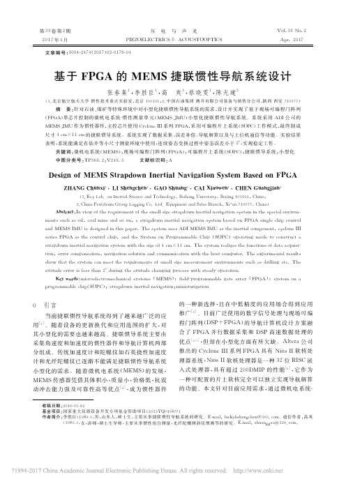
设计的捷联惯导系统包括惯性器件和导航计算 机两部分,传感器 采 用 MEMS 器 件IMU 采 集 加 速 度和角速度,输出各 自 感 应 轴 上 的 加 速 度 和 角 速 度 信息;导 航 计 算 机 主 控 芯 片 采 用 Altera公 司 的 Cy- clone III系列 FPGA,芯 片 利 用 通 用I/O 口 采 集 数 据到芯片内部,再由配置好的软核系统 Nios II处理 器进行导航 解 算,解 算 完 成 的 数 据 通 过 RS-232 串 口通信协议传给上位机显示。图1为具体的导航系 统原理图。
(1.北京航空航天大学 惯性技术重点实验室,北京 100191;2.中国石油集团 测井有限公司装备与销售分公司,陕西 西安 710077) 摘 要 :针 对 石 油 、煤 矿 等 特 殊 环 境 中 对 小 型 化 捷 联 惯 性 导 航 系 统 的 需 求 ,设 计 并 实 现 了 基 于 现 场 可 编 程 门 阵 列 (FPGA)单芯片控制的微 机 电 系 统-惯 性 测 量 单 元(MEMS_IMU)小 型 化 捷 联 惯 性 导 航 系 统。系 统 采 用 ADI公 司 的 MEMS_IMU 作为惯性器件,主控芯片使用 Cyclone III系列 FPGA,采 用 可 编 程 片 上 系 统(SOPC)工 作 模 式,最 终 制 成 尺寸4cm×11cm 的捷联惯导系统。系统实现了数据采集、误差补偿、导航解算以及与上位机通信等功能。实验结果 表 明 ,系 统 能 满 足 在 钻 井 等 小 尺 寸 测 量 环 境 中 使 用 ,连 续 姿 态 变 换 过 程 中 姿 态 误 差 小 于 2°,实 现 稳 定 工 作 。
3)分频 产 生 115 200 Hz 信 号 提 供 给 RS-232 模块,用作 RS-232协议波特率信号。
基于FPGA的机器人多路舵机控制器
第9卷 第11期 2009年6月167121819(2009)1123083204 科 学 技 术 与 工 程Science Technol ogy and Engineering Vol 19 No 111 June 2009Ζ 2009 Sci 1Tech 1Engng 1基于FPGA 的机器人多路舵机控制器王 倩 李冬雪(中国空空导弹研究院,洛阳471009)摘 要 设计了一种基于FPG A 的多舵机控制器,用于小型多关节机器人的控制中。
其优点是精度高,通道数多、硬件扩展方便,并大幅减少了软件编程量。
实验数据表明,该设计能够达到0.01°的角度分辨率。
并可在一片EP1C3T100的FPG A 上实现40路以上的舵机控制。
关键词 舵机控制 脉宽调制 现场可编程门阵列 机器人中图法分类号 T N492; 文献标志码 A2009年3月3日收到第一作者简介:王 倩(1981—),男,山东省新泰市人,工程师,硕士,研究方向:机载光电设备控制系统,E 2mail:wang_qian_mail@ 。
舵机由于结构形式紧凑,控制简单等优点,广泛应用于小型多关节机器人中,如小型人形机器人、六足仿生机器人等。
在这些应用中,需要对十几个舵机进行各自独立的控制,因此,多舵机的协调控制方法是小型多关节机器人的研究热点之一[1—3]。
本文介绍了舵机的控制原理,设计了基于FPG A (Field Pr ogra mmable Gate A rrays )的多舵机控制器,该控制器与顶层AR M 控制芯片一起构成了小型多关节机器人的硬件平台。
本文还进行了实验研究,对控制器的性能进行了测试。
1 舵机的控制原理舵机是一种集成了内部闭环电路和减速器的角位置伺服电机,一般有三根引线,分别是电源,地和控制信号。
控制信号为脉宽调制信号(P WM ),舵机的输出转角与脉冲宽度(每个周期中高电平的时间,以下简称脉宽)有固定的对应关系,只要给出一定脉宽的控制信号,舵机就会转到相应的角位置并保持该角位置不变,并且可以抵抗一定的外力。
基于FPGA的高速多通道AD采样系统的设计与实现_徐加彦
数转换芯片, 具有 8 通道同时采样,16 位输出的特
点,是一款高分辨率、双极性输入、同步采样的高性
能 模 数 转 换 芯 片 。 采 用 Altera 公 司 的EP2C35F672
可编程逻辑控制器件对 AD7606 进行时序控制。 并
在 FPGA 里设置一块双口 RAM,存储 AD7606 的数
输出条件
输出
图 2 有限状态机模型 Fig.2 Model of finite state machine
在数字电路中,状态机可用可编程逻辑控制器 件来建造,通过寄存器来储存状态变量,确定状态 转移的一块组合逻辑和确定状态机输出的另一块 组合逻辑。 2.3 时序程序的设计
有限状态机的设计对系统的高速性能、高可靠 性、稳定性都具有决定性作用。 采用状态机的形式, 在每个状态中,状态机可并行同步完成许多运算和 控制操作, 相比于 CPU 按照指令逐条运行的方式, 一 般 有 状 态 机 构 成 的 硬 件 系 统 比 对 应 的CPU 完 成 同样功 能 的 软 件 系 统 的 工 作 速 度 要 高 出 3~5 个 数 量级。 在可靠性能方面,状态机是在FPGA 通 过 纯 硬 件 电 路 构 成 , 其 运 行 不 依 赖 软 件 指 令 逐 条执行,因 此不存在 CPU 运行软件过程中的许多缺陷[3]。
基于FPGA的车辆自动驾驶控制系统设计(英文版)
Exploring the Role of Artificial Intelligence in Healthcare: Opportunitiesand ChallengesAbstractIn recent years, autonomous driving technology has received increasing attention. The use of Field Programmable Gate Arrays (FPGAs) in the design of autonomous driving control systems has become a popular research direction. In this thesis, we propose a design for a vehicle autonomous driving control system based on FPGA. The proposed system is implemented on a Zynq-7000 FPGA, which includes a dual-core ARM Cortex-A9 processor and programmable logic resources. The FPGA is used to implement real-time data processing and control algorithms, while the ARM processor handles higher-level tasks such as system management and communication with external devices. The proposed system is tested using a small-scale autonomous vehicle platform, and the experimental results demonstrate its feasibility and effectiveness.Keywords: autonomous driving, FPGA, control system, Zynq-7000IntroductionAutonomous driving technology has the potential to significantly improve the safety and efficiency of transportation systems. With recent advances in sensors, algorithms, and computing hardware, many companies and research institutions have been actively developing autonomous driving systems. One of the key challenges in autonomous driving is the design of a robust and reliable control system that can operate in real-time.Field Programmable Gate Arrays (FPGAs) are a type of reconfigurable computing device that can be programmed to perform specific tasks. FPGAs offer high computational performance, low power consumption, and flexible hardware customization, making them ideal for implementing real-time control algorithms in autonomous driving systems. Moreover, FPGAs can be integrated with other computing devices, such as microprocessors, to create hybrid systems that combine the benefits of both technologies.In this thesis, we propose a design for a vehicle autonomous driving control system based on FPGA. The proposed system is implemented on a Zynq-7000 FPGA, which includes a dual-core ARM Cortex-A9 processor and programmable logic resources. The FPGA is used to implement real-time data processing and control algorithms, while the ARM processor handles higher-level tasks such as system management and communication with external devices.System DesignThe proposed system consists of two main components: the hardware platform and the software architecture. The hardware platform is based on a Zynq-7000 FPGA, which includes a dual-core ARM Cortex-A9 processor and programmable logic resources. The FPGA is connected to various sensors and actuators, including cameras, LiDARs, and motor controllers. The software architecture is designed to implement real-time control algorithms and higher-level system functions.Figure 1 shows the block diagram of the proposed system. The FPGA is divided into two parts: the processing system (PS) and the programmable logic (PL). The PS contains the dual-core ARM Cortex-A9 processor, which is responsible for running the operating system (Linux) and high-level software modules. The PL contains the FPGA fabric, which is used to implement custom hardware modules for real-time data processing and control algorithms.The sensor data is collected by the sensor modules and sent to the PL for processing. The PL includes custom hardware modules for image processing, LiDAR data processing, and control algorithms. The processed data is sent back to the PS for higher-level control and communication with external devices. The PS also includes a CAN bus controller, which is used to communicate with the motor controllers.The software architecture is designed to support modular development and easy integration of new modules. The system is implemented using the Vivado Design Suite and Xilinx SDK, which provide tools for FPGA design and software development. The software modules are written in C/C++ and Python, and are compiled using the GNU Compiler Collection (GCC).Figure 1: Block diagram of the proposed system.Experimental ResultsThe proposed system was tested using a small-scale autonomous vehicle platform, as shown in Figure 2. The platform consists of a 1:10 scale RCcar equipped with a Zynq-7000 FPGA board, cameras, LiDARs, and motor controllers. The software modules were developed using the Vivado Design Suite and Xilinx SDK, and were tested on the platform in a simulated environment.The experimental results demonstrate that the proposed system is capable of real-time data processing and control. The image processing module was able to detect lane markings and obstacles in real-time, and the LiDAR data processing module was able to generate 3D point clouds and detect obstacles. The control algorithms were able to calculate steering and throttle commands based on thesensor data, and the motor controllers were able to execute the commands to control the RC car.To evaluate the performance of the system, we compared the execution time of the image processing module on the FPGA and on a desktop computer with a quad-core Intel Core i5 processor. The results showed that the FPGA was able to process images at a much faster rate than the desktop computer, with an average processing time of 11.4 milliseconds per frame compared to 30.3 milliseconds per frame on the desktop computer.ConclusionIn this thesis, we proposed a design for a vehicle autonomous driving control system based on FPGA. The proposed system was implemented on a Zynq-7000 FPGA, and was capable of real-time data processing and control. The experimental results demonstrated that the system was feasible and effective, and had better performance than a desktop computer for image processing tasks.Future work includes further optimization of the control algorithms and hardware modules, as well as integration with more advanced sensors and actuators. The proposed system has the potential to be applied to various autonomous driving scenarios, and could contribute to the development of safe and efficient transportation systems.。
基于FPGA的六轴机械手驱动控制系统设计与测试
基于FPGA的六轴机械手驱动控制系统设计与测试李磊; 任文杰【期刊名称】《《电气传动》》【年(卷),期】2019(049)012【总页数】6页(P52-57)【关键词】现场可编程门阵列(FPGA); 机械手; 多轴伺服控制; 模糊控制器; 比例积分控制器【作者】李磊; 任文杰【作者单位】河南农业职业学院信息工程学院河南郑州 451450【正文语种】中文【中图分类】TP241在工业4.0背景下,产业升级中工业机械手扮演着重要的角色。
目前工业机械手的多轴驱动器都是由一轴一个模组组成多轴控制,较少数使用多轴一体驱动器。
机械手的控制系统设计方案主要有:1)仅通过1个PC(personal computer)机实现控制,但无法处理复杂的作业任务,已被淘汰;2)工业计算机配置运动控制卡[1],是目前主流的方式,但是价格昂贵、控制算法不可重构;3)嵌入式处理器搭配智能伺服模块共同实现[2],但是价格高,不够成熟。
文献[3]利用FPGA实现了感应电机的神经网络控制,实现了感应电机的集成伺服控制。
利用FPGA实现多轴驱动器,以整合多轴伺服控制,包含位置、速度与电流回路等,以此实现驱动器的一体化,减少成本与体积。
本文以FPGA为基础实现六轴关节型机械手伺服驱动控制系统,并由六轴机械手验证定位精度,确定多轴一体驱动器的有效性。
相对于传统基于 DSP(digital signal processor)的控制系统,FPGA方案能够精简硬件电路设计,同时具有更好的灵活性。
1 六轴机械手控制系统组成FPGA芯片内包括1个NiosⅡ处理器的IP(intellectual property)核,1个六轴伺服控制IP核[4]。
NiosⅡ处理器IP负责点对点运动轨迹产生及动态性能响应信息收集等。
六轴伺服控制IP负责6个伺服控制模块,执行位置回路的模糊控制器、速度回路的PI(proportional integral)控制器电路、电流回路磁场导向控制器与坐标转换电路、空间向量脉宽调整电路(SVPWM)及绝对式编码器界面电路等功能,第i轴伺服控制器如图1所示。
基于FPGA的多源异构数据并行可配置采集方法
第27卷第4期计算机集成制造系统Vol.27No.4 2021年4月Computer Integrated Manufacturing Systems Apr.2021 DOI:10.13196/j.cims.2021.04.005基于FPGA的多源异构数据并行可配置采集方法李展鹏1,邹孝付",苏雍贺1,张长志彳,陶飞1(1.北京航空航天大学自动化科学与电气工程学院,北京100191;2.国网天津市电力公司电力科学研究院,天津300384)摘要:数据是支撑智能制造的关键要素,对生产各阶段数据的有效采集是实现“人一机一物一环境”制造全要素互联互通的基础。
随着制造升级发展,车间不断引入来自不同厂家,具有不同协议、不同接口的设备,使得待采集数据多源异构且采集需求不断变化。
传统数据采集设备难以并行采集多源异构数据、难以根据采集需求的动态变化对采集设备动态配置,因此提出一种基于现场可编程门阵列(FPGA)的多源异构数据并行可配置采集方法,基于FPGA硬件并行完成对多源异构数据的监测,保证数据采集实时性;研究FPGA动态重构技术并设计了数据采集可配置方法,提升数据采集灵活性;最后,设计了验证方案,验证了所提方法的有效性。
关键词:现场可编程门阵列;多源异构;数据采集;动态重构中图分类号:TP274.2文献标识码:AConfigurable acquisition method of multi-source heterogeneous data based on FPGALIZhanpeng1,ZOUXiaofu1+,SUYonghe1,ZHANG Changzhi2,TAO Fei1(1.School of Automation Science and Electrical Engineering,Beihang University,Beijing100191,China;2.State Grid Tianjin Electronic Power Research Institute,Tianjin300384,China)Abstract:Data is a key element supporting intelligent manufacturing.With the upgrading of manufacturing,the factory continuously introduces equipment from different manufacturers with different protocols and different interfaces.Data from that equipment collected has the characteristics of multi-source heterogeneity and constantly updated.Traditional data acquisition systems are customized for specific equipment,which is difficult to achieve parallel acquisition of multi-source heterogeneous data and real-time dynamic configuration.To solve these problems,a configurable acquisition method based on Field Programmable Gate Array(FPGA)was presented.Multi-source heterogeneous data were collected in parallel to ensure the real-time data acquisition.A configurable data acquisition scheme was designed to enhance the flexibility of data acquisition.A verification scheme was designed to verify the effectiveness of the proposed method.Keywords:field programmable gate array;multi-source heterogeneity;data acquisition;dynamic reconfiguration0引言随着云计算、大数据、物联网等新一代信息技术的发展以及信息化与工业化的“深度融合”,传统制造企业不断向智能制造的方向转型升级数据是智能制造的关键要素阂,只有在制造工厂底层实现对生产数据的有效感知,才能有效地完成工厂资源管理、车间计划与排产、生产过程监控等重要工收稿日期:2020-11-12;修灯日期:2020-11-25,,Received12Nov.2020;accepted25Nov.2020.基金项目:国家重点研发计划资助项目(2018YFB1500800);北京市科技重大专项资助项目(Z191100002719004);国家电网有限公司科技资助项目(SGTJDK00DYJS2000148)0Foundation items:Project supported by the National Key Research and Develapment Program,Chi-na(No.2018YFB1500800),the Beijing Municipal Science and Technology Major Project,China(No.Z191100002719004),and the Science and Technology Foundation of State Grid Corporation,China(No.SGTJDK00DYJS2000148).第4期李展鹏等:基于FPGA的多源异构数据并行可配置采集方法1009作闪。
- 1、下载文档前请自行甄别文档内容的完整性,平台不提供额外的编辑、内容补充、找答案等附加服务。
- 2、"仅部分预览"的文档,不可在线预览部分如存在完整性等问题,可反馈申请退款(可完整预览的文档不适用该条件!)。
- 3、如文档侵犯您的权益,请联系客服反馈,我们会尽快为您处理(人工客服工作时间:9:00-18:30)。
TechnicalnoteFPGAtechnologyformulti-axiscontrolsystems
ArmandoAstarloa*,JesúsLázaro,UnaiBidarte,JaimeJiménez,AitzolZuloagaUniversityoftheBasqueCountry,DepartmentofElectronicsandTelecommunications,FacultyofEngineering,Urquijos/n,E-48013Bilbao,Spain
articleinfoArticlehistory:Received24November2006Accepted1September2008
Keywords:PIDFPGADynamicreconfigurationSoCMotorcontrol
abstractTheresearchpresentedinthisarticleappliesthenewestField-Programmable-Gate-Arraystoimplementmotorcontrollerdevicesinaccordancewiththeactualcore-baseddesign.TheflexibilityoftheSystem-on-a-Programmable-Chipsinmotormulti-axiscontrolsystemsenablestheprocessingofthemostinten-sivecomputationoperationsbyhardware(PIDIPcores)andthetrajectorycomputationbysoftwareinthesamedevice.Inthosesystems,thetrajectorygenerationsoftwaremayruninpowerfulmicroproces-sorsembeddedintheFPGA.Inthispaper,wepresentahigh-performancePIDIPcorecontrollerdescribedinVHDL;thedesignflowthathasbeenfollowedinitsdesignandhowthesimulationandthePIDcon-stantstuninghasbeenapproached.Thereusabilityofthismoduleisdemonstratedwiththedesignofa4axisSoPCcontroller.Additionally,anexperimentalself-reconfigurableSoPCdesignusingRun-Time-Reconfigurationispresented.Inthiscase,thecontrolIPcorecanbereplaceddynamicallybyanothermodulewithanotherwithdifferentfeatures.Ó2008ElsevierLtd.Allrightsreserved.
1.IntroductionThemaindrawbacksofthetraditionalASICimplementationarethelackofflexibilityandthehighdevelopmentcosts.Field-Pro-grammable-Gate-Arrays(FPGAs)arehardwarein-systempro-grammabledeviceswhosefunctionisnotfixed.Specifically,themainadvantagesofalgorithmimplementationsusingFPGAsare:costefficiency,highdatathroughput,architectureefficiencyandabilitytomodifyandupdatethealgorithmevendynamically.Moreover,nowadaystheField-Programmable-Gate-Arraysarebigenoughtofitawholedigitalsysteminasingledevice.ThoseSystem-on-a-Chips(SoCs)aredesignedusingthecore-basedap-proach[1],interconnectingpre-designedhardwaremodules(IPcores)usingstandardon-chipbuses.ThisdesignflowisvalidforASICandFPGAdesign.SincethenumberanddiversityoftheavailableIPcoresforFPGAshasincreasedgreatly,theindustryisadoptingthecore-baseddesignmethodologymassivelyusingreconfigurabledeviceswhichleadstotheappearanceoftheSys-tem-on-Programmable-Chip(SoPC)platforms[2].ApartfromthefactthattheFPGAsdonotincurinnon-recurringengineeringchargesduetotheirreconfigurablenature,onemajorbenefitoftheseistheabilitytobereconfiguredduringtheexecutionoftheapplication,evenpartially.ThisfeaturecalledRun-TimeReconfig-uration(RTR)mustbeabletobeintegratedintocore-basedSoPCdesignflowshowingitsbenefitswhenappliedindividuallytoeachcore.Someofthebenefitsofcorecustomization,suchassize,powerandcomplexityreductionhavealreadybeenanalyzedby
theDepartmentofElectronicandElectricalEngineeringoftheUni-versityofStrathclyde(Glasgow).Theyfocusedtheirresearchontheapplicationofdynamicreconfigurationtoprogrammable,mul-tifunctioncores(PMCs)[3].InthiscategoryonecanfindcircuitssuchasUARTs,PCI,CRTandUSBcontrollers.AsanexampleoftheintroductionofRTRintothecores,theyobtainareareductionsofmorethan21%andasimultaneousincrementof14%inmaxi-mumoperatingspeedfortheUARTcase.WhentheRTRisappliedtoSoPCcorebaseddesigns,thespecificnameusedtoidentifythesesystemsisConfigurable-System-on-a-Programmable-Chip(CSoPC)designs[4–7].AlthoughmotorcontrolapplicationsareoneofthemostrecenttargetedfieldscoveredbySystem-on-Programmable-Chips[8],closed-loopcontrolalgorithmshavebeenstudiedandimple-mentedpreviouslyinFPGAs.Sametetal.implementthreediffer-entPIDarchitectures(parallel,serialandmixed)inaFPGA[9].Chenetal.presentin[10]afullwheelchaircontrollerimplementedonaFPGAusingaparallelPIDdesign.Zhaoetal.analyzethearea,speedandpowerconsumptiontrade-offbetweendifferentFPGAPIDimplementationsforsmall-scalerobots[11].TheSoPCsusedtoimplementmotorcontrolsystemsareveryflexibleindifferentways:thenumberandtypeofIPcoresandpro-cessors,busarchitectures,hardwareandsoftwareco-processing,etc.Thisflexibilityallowsamulti-axiscontrolsystemintegratinginasinglechip,notonlythecontrolIPcores,butalsotheremain-ingmodulesofthedigitalsystem.Theresearchworkpresentedinthisarticlecoversthethreemainadvancesinthisfield:IPcore,SoPCandCSoPC.InthefirstsectionanovelFPGAoptimizedandscalablePIDIPcoreispre-sentedtogetherwiththedesignflowthathasbeenfollowedin
0957-4158/$-seefrontmatterÓ2008ElsevierLtd.Allrightsreserved.doi:10.1016/j.mechatronics.2008.09.001
*Correspondingauthor.Tel.:+34946017304.E-mailaddress:armando.astarloa@ehu.es(A.Astarloa).