【精品】柴油机安装说明书
300KW柴油发电机组安装说明
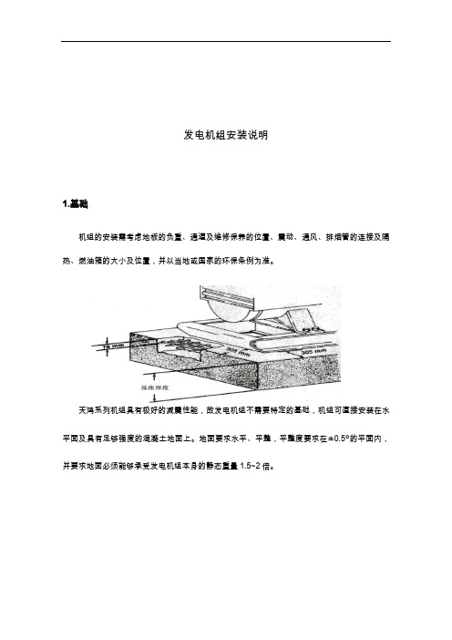
发电机组安装说明1.基础机组的安装需考虑地板的负重、通道及维修保养的位置、震动、通风、排烟管的连接及隔热、燃油箱的大小及位置,并以当地或国家的环保条例为准。
天鸿系列机组具有极好的减震性能,故发电机组不需要特定的基础,机组可直接安装在水平面及具有足够强度的混凝土地面上。
地面要求水平、平整,平整度要求在±0.5°的平面内,并要求地面必须能够承受发电机组本身的静态重量1.5~2倍。
2.机房机房必须有足够空间,以使空气自由循环,对于确保机组的正常使用性能、减少机组的功率损耗及保证机组的正常使用寿命等都是十分重要的。
机房内部不应放置其它易燃易爆物品和容易被卷入机组防护网罩甚至直接被吸入机体内部及可能影响机组的正常使用的任何物体。
为了防止热风回流,在机组冷却水箱与排风口间设有导风罩,防止热风在室内循环。
对于一般没有特殊要求的机组的安装施工,对机房的设计要求并不高,只需在保证排气背压不超出规定值的前提下,能够确保机房进风口和排风口满足技术规范的要求,并且避免暖气回流,而机房内部能够预留出足够的操作维修空间就可以了。
机房必须保证进风量,以补充消耗于发动机燃烧用的空气以及将机组运行时所散发出的大量热量通过散热器芯排出机房外,使机房内温度尽可能接近环境温度及保持机体温度于正常工作范围。
应确保排风口净面积最小不低于散热器芯有效面积的1.25倍,排风口中心位置应尽可能与机组散热器芯中心位置一致,排风口的宽高比也尽可能与散热器芯的宽高比相同。
福安市天鸿电机有限公司2017年3月31日常用300KW上柴股份(东风)系列柴油发电机组技术规格参数发电机组技术参数:机组型号:GF-S300 稳态电压调整率(%):≤±1常用功率:300Kw 电压波动率(%):≤±0.5额定功率因数:COSΦ=0.8(滞后)瞬态电压调整率(%):+20~-15额定输出电压:400V/230V 电压稳定时间(s):≤1额定电流(常用):540A 稳态频率调整率(%):≤±1额定频率:50Hz 频率波动率(%):≤±0.5额定转速:1500rpm 瞬态频率调整率(%):+10~-7启动控制方式:手动频率稳定时间(S):≤3燃油牌号:(标准)0#轻柴油(常温)燃油消耗(100%负载):207g/kW•h外形尺寸:2980×1150×1680(L×W×H mm)噪声(LP7m):100dB(A)机组重量:3300kg柴油机技术参数:品牌/产地:上柴股份(东风)冷却方式:封闭式水循环冷却型号:SC15G500D2 供油方式:直喷气缸数/敢提结构:6/L型调速方式:电子调速缸径行程:135×150 mm 进气方式:涡轮增压压缩比:16:1 过载能力:110%启动方式:DC24V电启动转速:1500rpm发电机技术参数:品牌/产地:天鸿电机(标配)/福建闽东防护等级:IP22型号:THW-300 接线方式:三相四线、Y型接法额定功率:300kW 调节方式:AVR(自动电压调节器)额定电压:400V/230V 输出频率:50Hz绝缘等级:H级输出因数:COSΦ=0.8(滞后)发电机组标准配置如下:直喷式内燃发动机(柴油);交流同步发电机(单轴承);适合环境40℃-50℃散热器水箱、皮带驱动冷却风扇、风扇安全护罩;发电输出空气开关、标配自启动控制系统;机组钢制共用底座(含:机组减振橡胶垫);干式空气过滤器,燃油过滤器,润滑油过滤器、启动马达、并配有自充电发电机;启动蓄电池及蓄电池启动连接电缆;工业用9dB消音器及连接用标准件随机资料:柴油机及发电机原厂技术文件、发电机组说明书等。
n620型柴油机说明书

N6210型柴油机使用说明书宁波中策动力机电集团有限公司2011年第一部份使用说是明书1柴油机及其附件介绍1.1基本术语1.1.1型号标注系列代号缸数缸径增压用途变型代号1.2.2自由端、输出端定义柴油机的飞轮是连接推进器等主要功率输出端,为飞轮端,与之相对应的为自由端。
1.2.3旋转方向自飞轮端面向自由端数,顺时针为右转,逆时针为左转。
1.2.4气缸编号自飞轮端面向自由端数,飞轮端为第一缸,依次类推。
1.2.5发火顺序六缸:右机:1-5-3-6-4-2八缸:右机:1-5-7-3-8-4-2-6左机:1-4-2-6-3-5左机:1-6-2-4-8-3-7-51.2.6左、右机定义自自由端向飞轮端视,油泵面在右侧为右机,在左侧为左机。
1.2柴油机的技术特点N210系列柴油机是消化吸由国外同类柴油机的先进技术基础上,采用现代先进计算机模拟技术,自主研制的新一代节能、环保型、能燃用重油的中速柴油机,是公司系列柴油机成轼进入市场后,其产品发展战略的延续。
其功率范围为396~1471KW,转速为600~1000r\min,可燃用3500S以下粘度的重油,性能指标先进,工作可靠,维修方便,外型美观,在相同的功率范围内该系列柴油机具有高度低、长度短、结构紧溱的优点。
N210柴油机为直列式、四冲程、增压中冷、直接喷射、不可逆转的柴油机,可以提供右机右转,右机左转、左机右转、左机左转。
其主要零部件有以下特点:1)机体采用曲轴悬挂式结构和零档轴承设计方式,机器振动小,曲轴饶曲小,传动精度高;2)曲轴为全平衡设计,有效减轻轴瓦的负荷,可以带前端输出;3)主轴瓦和连杆轴瓦采用最新的铜铅双层电镀合金技术,疲劳强度大大提高;4)伟分理处齿轮箱与机体铸为一体,机体采用水冷结构设计,凸轮轴操纵侧布置,机体整体铸造有气腔、水道、油道等,使得外围管路减少,减少了三漏的产生。
5)缸套上沿设计火焰环解镶圈,有效清除活塞头部积炭,减轻缸套的磨损,减少机油、燃油消耗,提高燃用重油的适用性,采用机体冷却水冷却;6)活塞顶的形式采用平顶浅W设计,适应燃油高压喷射的要求,环槽全部淬火硬提高燃重油的适应性;7)活塞环外围全部镀铬或CKS处理,提高燃重油的适应性;8)连杆采用船用三段式连杆,有效增加连杆轴颈,增加曲轴重叠度,提高曲轴强度,同时吊缸高度更低;9)气缸盖结构采用同侧进排气布置形式,采用V形盆腔,有效增加底板强度,减少热负荷;10)排气阀座强制水冷却,降低阀面温度,适应燃烧重油;11)凸轮轴采用分式结构布置,轴颈粗,刚性好,减小抽出长度;12)前端将机油、淡水冷却器、滤清器、调温阀布置一个模块里,用管路将水泵、机油泵联结;13)后侧布置气动启动马达,带有预啮合装置,启动安全可靠;14)中冷器布置在前端,设计壳体装配中冷器,支撑增压器,可根据用户要求需求安装在飞轮端;15)排气管船机采用脉冲,达到能量的良好利用,发电机组采用定压、采用独立支撑;16)燃油系统采用国外知名公司的设计,泵端压力达到150MPa,喷油器启喷压力达到38~45MPa,使燃油得到充分的雾化,油气混合均匀,提高燃油经济性;17)主要螺栓全部采用液压拉伸器紧固,螺栓受力均匀,零件的受力变形均匀;良好的设计有更高的可靠性和可维护性,众多的先进技术确保其有较长的吊缸间隔及较低的燃油和机油消耗率,N6210系列柴油机满足船舶入级建造规范和IMO组织对NOx排放的要求,适宜用于长江航运、拖轮、顶推轮、客货轮、工程船、渔船、船舶辅机,也可以用作陆用电站和其他动力装置。
12RT flex96C 柴油机说明书 01
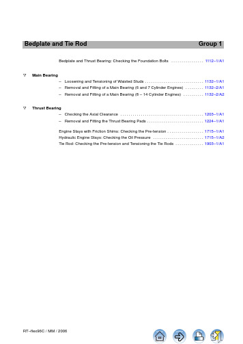
Bedplate and Tie Rod Group 1. . . . . . . . . . . . . . . .Bedplate and Thrust Bearing: Checking the Foundation Bolts1112–1/A1o Main Bearing. . . . . . . . . . . . . . . . . . . . . . . . . . . . .–Loosening and Tensioning of Waisted Studs1132–1/A1. . . . . . . . .–Removal and Fitting of a Main Bearing (6 and 7 Cylinder Engines)1132–2/A1. . . . . . . . . .–Removal and Fitting of a Main Bearing (8 – 14 Cylinder Engines)1132–2/A2o Thrust Bearing. . . . . . . . . . . . . . . . . . . . . . . . . . . . . . . . . . . . . . . . .–Checking the Axial Clearance1203–1/A1. . . . . . . . . . . . . . . . . . . . . . . . . . . .–Removal and Fitting the Thrust Bearing Pads1224–1/A1. . . . . . . . . . . . . . . . . .Engine Stays with Friction Shims: Checking the Pre-tension1715–1/A1. . . . . . . . . . . . . . . . . . . . . . . . .Hydraulic Engine Stays: Checking the Oil Pressure1715–1/A2. . . . . . . . . . . . . .Tie Rod: Checking the Pre-tension and Tensioning the Tie Rods1903–1/A1Tools:Key to Illustrations:1Feeler gauge941221Pin11Sleeve1Pre-tensioning jack941452Vent screw12Chock1HP oil pump949313Cylinder13Ship’s foundation plate 1Pressure gauge949324Piston14Nut1Pressure gauge94932a5Sealing ring15Conical socket1Hydr. distributor94934a6Nut1Plug piece94934e7Bedplate EV Relief valve1HP hose949358Foundation bolt KO Slot1HP hose94935a9Foundation fitted stud RS Round bar10Bush SAGapThe pre-tension of the foundation bolts (holding down studs) must be checked atlonger intervals e.g. during overhauls (see 0380–1).In the area of the thrust bearing the bedplate may be fastened with foundation bolts8, bushes 10 and sleeves 11 (Fig. ’A’) or with foundation fitted studs 9 (Fig. ’B’).The remaining area is fastened with foundation bolts 8 and bushes 10 (Fig. ’C’),however without sleeves 11.Remark: Pay attention to General Application Instructions 9403–4 for hydraulicpre-tensioning jacks.A BCBedplate and Thrust Bearing Checking the Foundation Bolts⇒Clean the threads of the foundation bolts and the seating surfaces. Subse-quently apply MOLYKOTE G paste to the threads.⇒Place pre-tensioning jack 94145 on foundation bolt 8 or fitted stud 9 to bechecked, and screw it completely down with vent screw 2 open until there is only little or no clearance at ’x’ (Fig. ’D’).⇒Connect the pre-tensioning jack with HP oil pump 94931 as shown in Fig. ’D’,whereby one side of hydr. distributor 94934a must be closed with plug piece 94934e.⇒Shut relief valve ’EV’ at the HP oil pump. Actuate HP oil pump till oil flowsbubble-free at vent screw 2.⇒Close vent screw 2, tension the foundation bolt with 1000 bar and keep pres-sure constant.DAttention should be paid to ensure that pin 1 always protrudes slightly compared with piston 4 on the pre-tensioning jack!Check with feeler gauge through slot ’KO’ if there is any clearance between nut 6and its seating.⇒If there is no clearance, this means that the tightening condition of the founda-tion bolt has remained unchanged since the last check. The pressure can be released to zero with relief valve ’EV’ and the pre-tensioning jack removed.Should a clearance be found, nut 6 must be tightened down onto its seating with round bar ’RS’ while the pressure is kept at 1000 bar (check with feeler gauge). Subsequently lower the pressure to zero.D2134Remark: If the foundation bolts have completely loosened and have to be ten-sioned again, then all foundation bolts have to be pre-tensioned first with 600 bar (1st step) and subsequently tensioned with 1000 bar (2nd step).CHECK⇒First screw down pre-tensioning jack 94145 as for checking the pre-tension,then turn back by ½ turn (gap ’SA’ in Fig. ’E’).⇒Connect the pre-tensioning jack with HP oil pump 94931 as shown in Fig. ’E’.⇒Shut relief valve ’EV’ at the HP oil pump. Actuate HP oil pump till oil flowsbubble-free at vent screw 2.⇒Close vent screw 2 and pump until a pressure of 1020 bar has been reached.DAttention should be paid to ensure that pin 1 always protrudes slightly compared with piston 4 on the pre-tensioning jack!⇒Turn back nut 6 by one turn, and release the pressure to ’0’.Remove the pre-tensioning jack.E213DTensioning of the foundation bolts must be carried out in two steps without exception, for both metal & synthetic chocks, i.e. tension all foundation bolts first with 600 bar (1st step), then finish tensioning with 1000 bar (2nd step).D Tensioning must be carried out as described in ’Checking the pre-tension’.DAttention should be paid to ensure that pin 1 always protrudes slightly compared with piston 4 on the pre-tensioning jack!Tools:Key to Illustrations:2Double pre-tensioning jacks 941141Waisted stud1Feeler gauge941222Main bearing cover 1Special feeler gauge 941233Nut1Depth gauge 941264Round nut 1Pressure gauge 94932a 5Piston 1Hydr. distributor 94934a 6Cylinder 1HP hose 949357Cover2HP hoses 94935a 8Tension sleeve 1Hydraulic unit949429Distance sleeve 10Main bearing girder 11Vent screwKO SlotRSRound barThe double pre-tensioning jacks 94114 must always be used for loosening as well as for tensioning the waisted studs 1 for the main bearing.Prior to screwing the nuts onto the waisted studs, threads and the nut seating sur-faces must be clean. Apply oil to the threads. Pay attention to the free movement of the nuts.Remark: Pay attention to General Application Instructions 9403–4 for hydraulicpre-tensioning jacks.⇒Screw tension sleeves 8 onto waisted studs 1 (Fig. ’B’).⇒Place distance sleeve 9.⇒Place both cylinders 6 with pistons 5 onto the distance sleeves.⇒Connect both double pre-tensioning jacks 94114 by HP hoses 94935 and94935a, hydr. distributor 94934a and pressure gauge 94932a with hydraulic unit 94942 (arrangement see Fig. ’C’).⇒Open vent screw 11.⇒Screw on round nuts 4 of the double pre-tensioning jacks till pistons 5 fullyseat on cylinders 6 (Fig. ’B’).The pistons are fully down on the cylinders when distance ’L 1’ is about 13 mm,measured from the top of the piston to the upper edge of cover 7.Check the oil level in hydraulic unit 94942.⇒Close vent screw.⇒Subsequently loosen all round nuts 4 by about ¾ to 1 turn.⇒Raise the pressure to 1020 bar at the hydraulic unit.⇒Unscrew nuts 3 by one turn with round bar ’RS’.⇒Release the pressure to zero at the hydraulic unit and then remove bothdouble pre-tensioning jacks.Main BearingLoosening and Tensioning of Waisted StudsCHECK⇒Fit the main bearing cover as described in 1132–2.⇒Tighten nuts 3 with round bar ’RS’ till firmly seated and mark these against thebearing cover = 1st step (Fig. ’A’).Determine with depth gauge 94126 distances a 1 and a 2. The difference between the two values must not be greater than 0.3 mm . If necessary adjust the bearing cover correspondingly by loosening and tensioning nuts 3 (Fig. ’C’).⇒Place both double pre-tensioning jacks 94114 onto waisted studs 1 for themain bearing as described under section 2 (Fig. ’C’).⇒Connect both double pre-tensioning jacks by HP hoses 94935 and 94935a,hydr. distributor 94934a and pressure gauge 94932a with hydraulic unit 94942 (arrangement see Fig. ’C’).⇒Open vent screw 11.⇒Screw on round nuts 4 of the double pre-tensioning jacks till piston 5 fully seaton cylinders 6 (Fig. ’B’).The pistons are fully down on the cylinders when distance ’L 1’ is about 13 mm,measured from the top of the piston to the upper edge of cover 7.Check the oil level in hydraulic unit 94942.⇒Close vent screw.⇒Actuate the hydraulic unit, adjust thepressure to 1000 bar (2nd step) and keep it constant.⇒Tighten all nuts 3 with round bar ’RS’till firmly seated.Using feeler gauge 94122 inserted in slot ’KO’, check if there is no clearance at hand between the nuts and the seating surfaces.⇒Release pressure to zero at the hy-draulic unit and then remove both double pre-tensioning jacks.CHECKATIGHTENINGANGLE1ST STEPCheck if all the nuts have been turned by about the same value, i.e. the tight-ening angle should be 130_ between the 1st and 2nd step (Fig. ’A’). If bigger differences occur the tensioning procedure must be repeated.Finally check the horizontal and vertical clearances by means of special feeler gauge 94123 (see Clearance T able 0330–1 ’Crankshaft and main bearing’).Recheck distances a 1 and a 2. If the difference exceed 0.3 mm, loosen the waisted studs, adjust the bearing cover correspondingly and repeat the tensioning proce-dure.Remark: All main bearing clearance values are valid only with tightened tie rods and waisted studs.CHECKCHECKCHECKC4 94114Tools:Key to Illustrations:1Lifting tool941161Crankshaft2Roller supports 941172Main bearing cover 1Turning-out device94118b 3Main bearing shell for narrow asymmetric bearing shell 4Locating dowel pin 1Turning-out device 94118c 5Groove for broad bearing shell 6Key1Turning-out device94118d 7Flywheelfor last bearing shell at free end 8Main bearing girder 1Lifting yoke 941199Guide shoe middle part 1Lifting eye bolt94120a 10Support2Ropes with shackle (300 mm)94120b 11Waisted stud 1Rope with shackle (500 mm)94120c 12Nut1Rope with shackle (600 mm)94120d 13Axial damper 1Rope with shackle (800 mm)94120e 14Support1Rope with shackle (1000 mm)94120f 15Intermediate wheel1Rope with shackle (1200 mm)94120g 16Spur-geared chain block 1Rope with shackle (1500 mm)94120h 17Connecting rod 1Rope with shackle (1600 mm)94120i 18Blank flange 1Rope with shackle (1700 mm)94120k 19Jack1Rope with shackle (1900 mm)94120l 20Suspension eye 1Rope with shackle (2000 mm)94120m 21Suspension eye 1Rope with shackle (2200 mm)94120n 22Strap1Rope with shackle (2800 mm)94120o 1Rope with shackle (3200 mm)94120p 2Ropes with 2 shackles (1000 mm)94120q 1Special feeler gauge 941231Support94141HO Wooden board 1Working platform 94142HZ Lifting tackle 1HP oil pump 94931H 1...Lifting tackles 1Hydr. distributor 94934a OB Oil bore1HP hose 94935RC Eye bolt M242HP hoses94935a RC 1Eye bolt M202Hydraulic jacks94936RC 2Eye bolt M20Overview1.Arrangement and characteristics of main bearings 2/22. . . . . . 2.Removal of main bearing cover No. 12/22. . . . . . . . . . . . . . . . . .3.Removal of main bearing cover No. 24/22. . . . . . . . . . . . . . . . . .4.Removal of main bearing cover No. 38/22. . . . . . . . . . . . . . . . . .5.Removal of main bearing cover No. 410/22. . . . . . . . . . . . . . . . .6.Removal of main bearing shells 12/22. . . . . . . . . . . . . . . . . . . . . .7.Fitting of main bearing shell and main bearing cover 19/22. . Remark: Pay attention to:–General Guidelines for Lifting T ools 0012–1.–Utilization of Working Platform and Ladder 3301–1.Main BearingRemoval and Fitting of a Main Bearing6 and7 Cylinder EnginesA3612Cross section of main bearing:38462⇒Turn crank 1 to exhaust side approx. 100_after T .D.C. (Fig. ’D’).⇒Remove upper part of oil baffle at the driving end.⇒Remove oil piping from thrust bearing.⇒Loosen nuts 12 for waisted studs 11 (Fig. ’A’) hydraulically (see 1132–1).⇒Screw eye bolt ’RC’ into main bearingcover (bearing cover for short) 2.⇒Fasten lifting eye bolt 94120a to thecolumn.⇒Pull rope ’a’ (94120f) through a holein intermediate wheel 15 and connect it with eye bolt ’RC’ and lifting tackle H 1.⇒Connect rope ’b’ (94120b) with eyebolt ’RC’ and lifting tackle H 2 which is fastened to the inner suspension eye of support 10.⇒Lift bearing cover 2 over the waistedstuds with ropes ’a’ and ’b’ and then swing it towards flywheel 7.⇒Detach rope ’a’.5 to sus-6 to sus-014.586/06⇒Remove upper part of oil baffle at thedriving end.⇒Turn corresponding crank to exhaustside approx. 90_after T.D.C.⇒Install working platform 94142.⇒Remove oil piping from thrust bearing.⇒Loosen nuts 12 to waisted studs 11(Fig. ’A’) hydraulically (see 1132–1).⇒Fasten roller support 94117 to guideshoe middle part 9 (see detail in Fig.’F’).⇒Screw eye bolt ’RC’ into bearing cover.⇒Connect rope ’e’ (94120k) with eye bolt’RC’ and lifting tackle H 1 via roller sup-port as shown in Fig. ’E’ and ’F’.⇒Fasten lifting tackle H 2 to the outersuspension eye of support 10.⇒Pull rope ’a’ (94120f) through a hole inintermediate wheel 15 and connect it with eye bolt ’RC’ and lifting tackle H 2.⇒Provide protection for the crank web.9411792H 1H H 1⇒Lift bearing cover with ropes ’a’ and ’e’.⇒Loosen rope ’a’ until bearing cover liesat the crank web.⇒Instead of rope ’a’ connect rope ’d’(94120c) with lifting tackle H 2 as shown in Fig. ’H’.⇒Screw two eye bolts ’RC 1’ and ’RC 2’laterally into the bearing cover.⇒Connect rope ’f’ (94120q) with eyebolts ’RC 1’ and rope ’d’.RC 2H1KRC 94120a H 3014.591/06⇒Lift the bearing cover carefully over the crank web with ropes ’d’, ’f’ and ’e’.⇒Remove ropes ’d’ and ’f’.⇒Fasten lifting eye bolt 94120a to the column as shown in Fig. ’I’ and detail concerned in Fig. ’C’.⇒Connect rope ’f’ (94120q) with eye bolts ’RC 2’ and lifting tackle H 3.The further removal of the bearing cover is car-ried out analogously as described for Fig.’K’–’M’.⇒Fasten lifting tackle ’HZ’ to strap 22.⇒Connect rope ’g’ (94120e) with eyebolts ’RC’ and lifting tackle ’HZ’.⇒Lift the bearing cover carefully overthe crank web with ropes ’e’ and ’f’ to-wards middle of cylinder (Fig. ’I’) and pull it with rope ’g’ to fuel side at the same time (Fig. ’K’).HLM014.592/06014.593/06⇒Guide the bearing cover to fuel sidewith ropes ’g’ and ’e’ until rope ’h’(94120m) can be connected with lift-ing tackle H 4 and eye bolt ’RC’.⇒Place bearing cover on working plat-form 94142.⇒Remove rope ’e’.⇒Lift the bearing cover out of the crank-case using ropes ’g’ and ’h’.⇒Turn the corresponding crank to exhaust side approx. 90_ after T .D.C. (Fig.’E’).⇒Install working platform 94142 (Fig. ’E’).⇒Loosen nuts 12 for waisted studs 11 (Fig. ’A’) hydraulically (see 1132–1).⇒Screw a roller support 94117 each onto guide shoe middle parts 9 as shown inFig. ’N’ and detail concerned in Fig. ’F’.⇒Fasten lifting eye bolt 94120a to the column (see detail concerned in Fig. ’C’).⇒Screw eye bolt ’RC’ into bearing cover.⇒Connect rope ’e’ (94120k) with eye bolt ’RC’ and lifting tackle H 1 as shown inFig. ’E’ and ’N’.⇒Connect rope ’x’ (94120n–p) with eye bolt ’RC’ and lifting tackle H 2 (ropes ’x’differ in lengths depending on the position of the guide shoes).⇒Provide protection for the crank web.NH 3RC 2H 2994120aRC94117H 194117⇒Lift the bearing cover carefully overthe crank web with ropes ’x’ and ’e’and detach rope ’x’.⇒Screw two eye bolts ’RC 2’ laterallyinto the bearing cover and connect them with rope ’f’ (94120q) and lifting tackle H 3.⇒Pull bearing cover with ropes ’e’ and’f’ towards middle of cylinder.The further removal of the bearing cover is carried out analogously as described for Fig. ’O’–’Q’.⇒Fasten lifting tackle ’HZ’ to strap 22.⇒Connect rope ’g’ (94120e) with eyebolts ’RC’ and lifting tackle ’HZ’.⇒Lift the bearing cover carefully overthe crank web with ropes ’e’ and ’f’ to-wards middle of cylinder (Fig. ’I’) and pull it with rope ’g’ (Fig. ’O’) to fuelside at the same time.⇒Guide the bearing cover to fuel sidewith ropes ’g’ and ’e’ until rope ’h’(94120m) can be connected with lift-ing tackle H 4 and eye bolt ’RC’.O014.599/06P014.600/06⇒Place bearing cover on working plat-form 94142.⇒Remove rope ’e’.⇒Lift the bearing cover out of the crank-case using ropes ’g’ and ’h’.Q014.601/06⇒Turn crank of the last cylinder to exhaust side approx. 90_ after T .D.C. (Fig. ’E’).⇒Install working platform 94142 (Fig. ’E’).⇒Loosen nuts 12 for waisted studs 11 (Fig. ’A’)hydraulically (see 1132–1).⇒Screw eye bolt ’RC’ into bearing cover.⇒Remove blank flange 18 from casing upper part.⇒Fasten lifting tackle H 2 to support 14 and connect rope ’d’ (94120c) with eye bolt ’RC’.⇒Fasten roller support 94117 to guide shoe middle part 9 (see detail concerned in Fig.’F’).⇒Connect rope ’e’ (94120k) with eye bolt ’RC’and lifting tackle H 1 via roller support 94117as shown in Fig. ’E’ and ’R’.⇒Provide protection for the crank web.RH 1RC 2⇒Screw two eye bolts ’RC 1’ and ’RC 2’ lateral-ly into the bearing cover.⇒Fasten lifting eye bolt 94120a to the column (see detail concerned in Fig. ’C’).⇒Connect rope ’d’ with eye bolt ’RC 2’ and lift-ing tackle H 2.⇒Connect rope ’f’ (94120q) with eye bolt ’RC 1’and lifting tackle H 3.⇒Lift the bearing cover carefully over the crank web with ropes ’d’, ’e’ and ’f’ towards middle of cylinder.The further removal of the bearing cover is car-ried out analogously as described for Fig.’O’–’Q’.⇒Lift the bearing cover carefully as much as possible with ropes ’d’ and ’e’ and detach rope ’d’ from eye bolt ’RC’.H 2H 2Never remove two neighbouring bearing shells at the same time.D The same lifting tackles are used for the removal of the corresponding bearing shells as for the removal of the corresponding bearing covers.DFor the removal of bearing shells No. 1 and 2 the flywheel must also be pressed up with the additional hydraulic jack 19. T o protect the flywheel tooth-ing, put a copper or aluminium plate between the hydraulic jack and the fly-wheel (Fig. ’Z’).U6.1Fitting the hydraulic jacks ⇒Turn crankshaft 1 to exhaust sideapprox. 90_ after T.D.C.⇒Put support 94141 on two main bear-ing girders 8 parallel to the engine axis.⇒Place hydraulic jacks 94936 on sup-port 94141.⇒Connect the hydraulic jacks with HPhoses 94935 and 94935a, as well as hydr. distributor 94934a to HP oil pump 94931.94141949368I - I94141949366.2Lifting the crankshaft⇒Using hydraulic jacks 94936 and liftthe crankshaft at the bearing to be re-moved by value ’x’ = 0.4–0.5 mm.Attention! Lift the crankshaft max. to the point where the neighbouring main bear-ings show vertically no clearance any more between the main bearing cover and crankshaft.Check this procedure with a dial gauge installed above the crankshaft, and verify the bearing clearance at the neighbouring main bearings using special feeler gauge 94123.W6.3Turning out the main bearing shells Bearing No. 1, see Fig. ’Z’:DThe same ropes and arrangement are used for turning out and lifting of the bearing shells, however, rope 94120g must be replaced by rope 94120h.Bearing No. 2, see Fig. ’A 1’:DThe same ropes and arrangement are used for turning out and lifting of the bearing shell, however, rope 94120i must be replaced by rope 94120l, and rope 94120g must be replaced by rope 94120h.Bearing No. 3, see Fig. ’Y’:DThe same ropes and arrangement are used for turning out and lifting of the bearing shells, however, rope 94120i must be replaced by rope 94120l.Bearing No. 4, see Fig. ’B 1’:DThe same ropes and arrangement are used for turning out and lifting of the bearing shells, however, rope 94120i must be replaced by rope 94120l, and rope 94120d must be replaced by rope 94120f.D The turning-out procedure is the same for all bearing shell as described for Fig. ’X’.DTurning-out devices 94118b, 94118c or 94118d are provided depending on the location of the bearing shell as shown in Fig. ’W’.CHECKD R I V I N G6.3.1Turning out the main bearing shell No. 3 (example)⇒Fasten turning-out device 94118c on the joint face of the bearing shell utilizingits proper screws (view III ).⇒Lead both ropes of the turning-out device along the lateral edges of the mainbearing shell 3 to the other side and connect them with lifting yoke 94119 as shown in view II .Remark: By means of a wire attached to the ropes they can be pulled below the bearing journal to the other side. This may be of help primarily for bearings No. 1, 2and 4.⇒With ropes ’x’ (94120n–p) and ’e’ (94120l) connected to lifting tackles H 2 andH 1 pull bearing shell slowly out from the bearing girder till both ends of the bearing shell are free (no meshing).⇒Remove lifting yoke 94119 and rope ’e’.X94141H 294119949369411736.4Removal of main bearing shells No. 3⇒Fasten lifting tool 94116 onto bearing shell 3 and connect it with ropes ’x’(94120n–p) and ’e’ (94120i) as shown in view II .⇒Lift the bearing shell carefully over the crank web with ropes ’x’ and ’e’.⇒Loosen and remove rope ’x’.⇒Connect lifting tackle H 3 directly to lifting tool 94116 and pull bearing shell to-gether with rope ’e’ towards middle of cylinder.⇒Fasten lifting tackle ’HZ’ to strap 22.⇒Connect rope ’g’ (94120f) with lifting tackle ’HZ’ and lifting tool, and then pullthe bearing shell together with rope ’e’ and lifting tackle H 3 to fuel side (view I-I).The further procedure is carried out analogously as shown in Fig. ’P’ and ’Q’ (Re-moval of main bearing cover).39411694116H H 1H 36.5Removal of main bearing shell No. 1⇒Fasten lifting tool 94116 onto the bearing shell 3.⇒Fasten lifting eye bolt 94120a to the column (see detail concerned in Fig. ’C’).⇒Pull rope ’a’ (94120g) through a hole in intermediate wheel 15 and connect itwith eye bolt ’RC’ and lifting tackle H1.⇒Connect rope ’b’ (94120b) with lifting tool 94116 and lifting tackle H2 which isfastened to the inner eye of support 10.⇒Lift bearing shell with ropes ’a’ and ’b’ and then swing it towards flywheel 7.⇒Detach rope ’a’.⇒Fasten lifting tackle H5 to suspension eye 20 and connect rope ’c’ (94120b)with lifting tool, and subsequently swing it towards fuel side with ropes ’b’ and’c’ as shown in view I.⇒Fasten lifting tackle ’HZ’ to suspension eye 21 and connect it to bearing shell 3and then swing the latter fully towards fuel side.⇒Remove rope ’c’.6.6Removal of main bearing shell No. 2⇒Fasten lifting tool 94116 onto the bearing shell 3.⇒Pull rope ’a’ (94120g) through a hole in intermediate wheel 15 and connect itwith lifting tool.⇒Lead rope ’e’ (94120i) over roller support 94117 and connect it with liftingtackle H 1 and lifting tool.⇒Lift the bearing shell carefully over the crank web with ropes ’a’ and ’e’.⇒Remove rope ’a’.⇒Connect lifting tackle H 3 directly to lifting tool 94116 and pull bearing shell to-gether with rope ’e’ towards middle of cylinder.⇒Fasten lifting tackle ’HZ’ to strap 22.⇒Connect rope ’g’ (94120f) with lifting tackle ’HZ’ and lifting tool, and then pullthe bearing shell together with rope ’e’ and lifting tackle H 3 to fuel side (view I-I).The further procedure is carried out analogously as shown in Fig. ’L’ and ’M’ (Re-moval of main bearing cover).A 1I - I136.7Removal of main bearing shell No. 4⇒Fasten lifting tool 94116 onto the bearing shell 3.⇒Connect rope ’d’ (94120d) with lifting tool.⇒Lead rope ’e’ (94120i) over roller support 94117 and connect it with liftingtackle H1 and lifting tool.⇒Lift the bearing shell carefully over the crank web with ropes ’e’ and ’d’.⇒Remove rope ’d’.⇒Connect lifting tackle H3 directly to lifting tool and pull bearing shell togetherwith rope ’e’ towards middle of cylinder.⇒Fasten lifting tackle ’HZ’ to strap 22.⇒Connect rope ’g’ (94120f) with lifting tackle ’HZ’ and lifting tool, and then pullthe bearing shell together with rope ’e’ and lifting tackle H3 to fuel side (viewI-I).The further procedure is carried out analogously as shown in Fig. ’P’ and ’Q’ (Re-moval of main bearing cover).B1I - IH3DPrior to fitting a bearing shell or bearing cover pay attention to ’Arrangement and characteristics of the main bearings’ on page 2.Remark: As the bearing shell and bearing cover of variant 2 are machined togeth-er, they have to be considered as a unit, and must therefore not be interchanged!In case of damage they must always be substituted as whole unit . Bearing shell and bearing cover are marked with a common serial number.D Step of key 6 in bearing shell of variant 1 must point inwards as shown in Fig.’C 1’.DArrows on broader sides (Fig. ’C 1’) ensure the proper fitting direction of asym-metric bearing shells No. 1 & 2. In addition bearing shell No. 2 is laterally marked with DRIVING END.Attention! Always fit asymmetric bearing shells No. 1 and 2 in direction of arrow as shown in Fig. ’D 1’.DBearing shells No. 3 & 4 and all bearing covers are laterally marked with DRIVING END. Therefore, they must be fitted correspondingly.C 1D 1014.684/06I - IVARIANT NUMBERBEARING NUMBER(DO NOT CORRESPOND TO OFFICIAL MAIN BEARING NUMBERING 0008–1)D R I V I N GD Bearing shell and bearing cover should be fitted into the bearing girder in their original positions.D Oil bore ’OB’ in the bearing girder must be clean and without particles of white metal.DCrankshaft journal, girder bore for main bearing and all parts to be fitted must be clean and undamaged!Cross section of main bearings (numbering):E 1F 1D R I V I N GE NDNo. 2No. 1No. 3 and 4The fitting of bearing shell and bearing cover is carried out analogously but in re-verse sequence to the removal.⇒Directly before fitting (turning in) bearing shell 3 apply a very thin layer ofMOLYKOTE paste G to the back of it.⇒The crankshaft journal and the running surface of the main bearing shell mustbe thoroughly lubricated with clean engine oil.7.1Turning in the main bearing shell(see Fig. ’G 1’ as an example for main bearing No. 3)⇒Connect ropes ’x’ and ’e’ with lifting yoke 94119.⇒Lead both ropes of turning-out device 94118c below of the crankshaft journal to the fuel side and connect them with lifting yoke 94119.DSo that bearing shell does not glide jerkily, it must be held and guided slowly into the bearing girder at the ends of the ropes.⇒Pull bearing shell to its proper position with ropes ’x’ and ’e’.⇒Release the pressure at the HP oil pump and fit bearing cover 2. The latter can be fitted by means of lifting tackles and ropes as described for the removal, but in reverse sequence.DBe careful that keys 6 mesh with the corre-sponding keyways in bearing cover 2 (Fig.’A’).⇒Tighten nuts 12 for waisted studs 11 follow-ing the instructions in 1132–1.⇒Remove all the tools from the engine and below of the flywheel.G 1The bearing clearances and the crank deflection must be measured after a new bearing shell has been fitted and the bearing cover has been tightened (see 0330–1 and 3103–1).After assembly, check if lubricating oil is supplied to the main bearing with the oil pump in operation!CHECKRemark: Should the crankshaft need to be turned before the bearing cover is fitted, then care must be taken that the bearing shell does not turn. Therefore,bearing shell 3 must be blocked with two suitable wooden boards ’HO’.H 1812HO 1113Tools:Key to Illustrations:1Lifting tool941161Crankshaft2Roller supports 941172Main bearing cover 1Turning-out device94118b 3Main bearing shell for narrow bearing shell 4Locating dowel pin 1Turning-out device 94118c 5Groove for broad bearing shell 6Key1Turning-out device94118d 7Flywheelfor bearing shell at free end 8Main bearing girder 1Lifting yoke 941199Guide shoe middle part 1Lifting eye bolt94120a 10Support2Ropes with shackle (300 mm)94120b 11Waisted stud 1Rope with shackle (500 mm)94120c 12Nut1Rope with shackle (600 mm)94120d 13Vibration damper 1Rope with shackle (800 mm)94120e 14Support1Rope with shackle (1000 mm)94120f 15Intermediate wheel1Rope with shackle (1200 mm)94120g 16Spur-geared chain block 1Rope with shackle (1500 mm)94120h 17Connecting rod 1Rope with shackle (1600 mm)94120i 18Blank flange 1Rope with shackle (1700 mm)94120k 19Jack1Rope with shackle (1900 mm)94120l 20Suspension eye 1Rope with shackle (2000 mm)94120m 21Cover1Rope with shackle (2200 mm)94120n 22Casing, upper part 1Rope with shackle (2800 mm)94120o 23Oil baffle, upper part 1Rope with shackle (3200 mm)94120p 24Suspension eye 2Ropes with 2 shackles (1000 mm)94120q 25Strap1Special feeler gauge 941231Support94141HO Wooden board 1Working platform 94142HZ Lifting tackle 1HP oil pump 94931H 1...Lifting tackles 1Hydr. distributor 94934a OB Oil bore1HP hose 94935RC Eye bolt M242HP hoses94935a RC 1Eye bolt M202Hydraulic jacks94936RC 2Eye bolt M20Overview1.Arrangement and characteristics of main bearings 2/26. . . . . .2.Removal of main bearing cover No. 13/26. . . . . . . . . . . . . . . . . .3.Removal of main bearing cover No. 24/26. . . . . . . . . . . . . . . . . .4.Removal of main bearing cover No. 38/26. . . . . . . . . . . . . . . . . .5.Removal of main bearing cover No. 49/26. . . . . . . . . . . . . . . . . . 6.Removal of main bearing cover No. 513/26. . . . . . . . . . . . . . . . .7.Removal of main bearing shells 15/26. . . . . . . . . . . . . . . . . . . . . .8.Fitting of main bearing shell and main bearing cover 23/26. . Remark: Pay attention to:–General Guidelines for Lifting T ools 0012–1.–Utilization of Working Platform and Ladder 3301–1.Main BearingRemoval and Fitting of a Main Bearing8 – 14 Cylinder Engines。
柴油发电机组安装指南
1#油机
2#油机
需封口或套波纹 软管的地方
3.日用外置补油箱的安装规范 日用外置补油箱的采用,主要适应于无人值守的野外通讯基站,满足长时间机组
运行的自动供油.从实际使用条件和环境考虑,一般通讯基站里采用无动力自动 供油系统.下面以无动力供油系统为例进行说明. * 基础的制作要求 ①油箱基础和发电机组的基础在同一水平面,或油箱基础高于机组的基础. ②紧固螺丝的安装方式等同油机的方式。 ③油箱在基础台上摆放居中,端正。用膨胀螺栓固定,固定后油箱整体保持水平, 端正。 ④摆放后油箱进、回管侧面与基础台的端部距离为 20cm;油机左右两侧和排风端 部距基础台边沿的距离各为 10cm。 ⑤基础台制作要求(筑造方式等同于机组基础台)的基础图如下:
西电柴油发电机组 安装指南
(一主一备双油机站点)
西电(汕头保税区)动设备有限公司 WESTINPOWER (SHANTOU F. T. Z.) Co. Ltd,
目录
一、安装工具
1.施工单位需要准备常规安装工具
二、安装材料
1.随机配套材料一 2.随机配套材料二
图二:(冲击钻一把,钻头若干)
图三:12 件套开口扳手一套
备注:安装队还需准备挖电缆沟用的土铲。
西电(汕头保税区)动力设备有限公司 WESTINPOWER (SHANTOU F. T. Z.) Co. Ltd,
二、 安装材料: 图 1.随机配套材料一,(除长螺丝栓外,其它为随机配套):生料带;绝缘胶带; 塑料扎线带;穿油管和线缆用的 PVC 管;能穿透房舱墙壁的螺栓及配套螺母, 垫片,螺栓长 9cm,φ6/8mm;
柴油发电机组安装指南
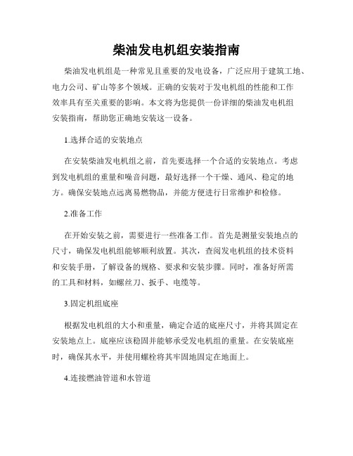
柴油发电机组安装指南柴油发电机组是一种常见且重要的发电设备,广泛应用于建筑工地、电力公司、矿山等多个领域。
正确的安装对于发电机组的性能和工作效率具有至关重要的影响。
本文将为您提供一份详细的柴油发电机组安装指南,帮助您正确地安装这一设备。
1.选择合适的安装地点在安装柴油发电机组之前,首先要选择一个合适的安装地点。
考虑到发电机组的重量和噪音问题,最好选择一个干燥、通风、稳定的地方。
确保安装地点远离易燃物品,并能方便进行日常维护和检修。
2.准备工作在开始安装之前,需要进行一些准备工作。
首先是测量安装地点的尺寸,确保发电机组能够顺利放置。
其次,查阅发电机组的技术资料和安装手册,了解设备的规格、要求和安装步骤。
同时,准备好所需的工具和材料,如螺丝刀、扳手、电缆等。
3.固定机组底座根据发电机组的大小和重量,确定合适的底座尺寸,并将其固定在安装地点上。
底座应该稳固并能够承受发电机组的重量。
在安装底座时,确保其水平,并使用螺栓将其牢固地固定在地面上。
4.连接燃油管道和水管道柴油发电机组需要连接燃油管道和水管道以供应燃油和冷却水。
首先,根据技术资料确定管道规格和类型。
然后,将管道连接到相应的接口上,并使用密封胶密封连接处,确保不会发生泄漏。
5.接地发电机组的安装必须进行接地处理,以确保人身安全和设备的正常运行。
首先,选择适当的接地装置,并将其连接到发电机组上。
接着,选择合适的接地点,确保接地电阻符合国家标准。
最后,将接地线连接到接地点上,并进行必要的测试,确保接地有效。
6.电气连接在进行电气连接之前,请务必切断电源。
将发电机组的输出线与主配电盘进行连接,根据接线图将线缆正确连接到相应位置。
确保所有连接牢固可靠,并使用绝缘胶带对接线进行绝缘处理。
完成连接后,仔细检查一遍,确保没有错误和短路等问题。
7.检查设备在安装完成后,进行设备的全面检查是非常重要的。
首先,检查燃油和水管道是否正确连接,并进行泄漏测试。
然后,检查电气连接是否牢固,各个电器元件是否正常工作。
CLARKE柴油机说明指导书

目录安装步骤及注意事项 (1)维护手册 (4)柴油机水泵调试步骤 (7)安装步骤及注意事项正确安装对于取得发动机最好性能及延长其使用寿命是至关关键。
所以,对于机器安装提出了很多关键要求,关键是针对冷却系统、排气系统、吸气系统和燃料系统。
安装时,全部安装面必需保持清洁、无杂物且要干燥。
同时也要确保保养和维修通道通畅。
在安装布局设计中,必需把发动机运转时人身安全保障放在首位进行考虑。
安装内容:1. 确保地基可靠,并按安装说明进行安装,同时完成发动机到水泵联轴器安装。
1.1驱动轴安装为了检测水泵轴和发动机轴同轴度误差和角度误差,驱动轴必需安装在调速轮驱动盘和泵轴法兰之间。
先拆掉蓄电池负极电缆线,然后再拆掉驱动轴护罩。
另外还需要一最小单位为毫米刻度尺或直尺进行安装中测量。
检测联轴器步骤以下:A)在确保驱动轴正确位置前提下,检测发动机轴和泵轴两轴线同轴度误差。
手动旋转发动机轴,需测尺寸图4,图5所表示:A点测量结果应该在下表许可误差范围内:MEASUREMENT MODELS58 + 2mm. IK6H-UF20,IK4H-LP50IK4H-NL40, 50, IK4R-NL40, 4968 + 4mm. IK6R-UF11, 15, 19 IK6H-LP30, 60IK6H-NL20, 30, 40, 50, 60IK6R-NL29, 39, 49, 5976 + 3mm.IK6H-UF60, 80IK6H-LP80IK6H-NL70, 80IK6R-NL69, 79B)B点测量结果和A点相差1mm。
C)C点测量结果应该在下表许可误差范围内:D)D点测量结果和C点相差1mm。
假如测量结果不满足要求,能够经过调整发动机左右位置和高低位置来进行调整。
注:在进行测量之前,必需确保安装在防振垫上发动机是固定不动。
测量完成后,装好防护罩及蓄电池电缆线。
驱动轴维护1)在维修驱动轴前,先拆下蓄电池负极电缆线及防护罩。
CAT 3512 TA 柴油发动机 说明书
柴油机发电机组主电源1020ekW 1275kVA 50Hz 1500rpm 11000电压Caterpillar 凭借其Power Solutions 引领发电产品市场,Power Solutions 经过精心打造,可为客户提供无以比拟的灵活性、可扩展性、可靠性及成本有效性。
所示图像可能无法反映真实套件。
特性燃油/排放策略•低油耗设计标准•根据NFPA 110发电机组加载一步式100%额定负载,达到ISO 8528-5瞬时反应标准全范围附件•品种多样的用螺栓固定的系统扩展附件,由工厂设计和测试•软包装选项,使安装简化并获得最高成本效益世界范围产品支持•Cat 代理商提供广泛的售后支持,包括维护和维修协议•Cat 代理商在200个国家内开设1800家以上代理商分店。
•Cat®S•O•S SM 计划以高成本效益检测内部发动机部件状况,即使在出现有害油液和燃烧副产品时也不例外CAT®3512TA 柴油发动机•可靠、坚固、耐用的设计•在全世界成千上万的应用中现场验证•四冲程循环柴油发动机,性能稳定、燃油经济性优异并且重量最轻CAT HV 发电机•与Cat 发动机的性能和输出特性匹配•单点检视附件连接•UL 1446认可的F 级绝缘CAT EMCP 4控制面板•简单的用户方便型接口和导航•可扩展系统,符合大范围客户需求•整体式控制系统和通信网关工厂安装的标准和选用设备技术规格CAT发电机Cat HV发电机支架尺寸 (2730)励磁............................................................................永久磁体节距...............................................................................0.6670电极数量 (4)轴承数量 (2)引线数量 (12)绝缘..........................................................F级(耐热和耐磨)-请向您的Cat代理商咨询,了解可用电压IP防护等级........................................................................IP23对中...............................................................................紧连接超速功能........................................................额定转速的125%波形偏差(线间)...............................................................2%电压调节器.......................................伏特/赫兹信号的3相传感电压调节........................................小于+/-1/2%(稳定状态)小于+/-1%(空载至满载)电话干扰系数.................................................................小于50谐波失真......................................................................小于5%CAT柴油发动机3512TA,V-12,四冲程水冷柴油发动机缸径.........................................................170.00mm(6.69in)冲程.........................................................190.00mm(7.48in)排量.........................................................51.80L(3161.03in3)压缩比.............................................................................13.5:1进气方式.......................................................................ATAAC 燃油系统.................................................................单体泵直喷调速器类型.....................................伍德沃德(Woodward)公司CAT EMCP4系列控制装置EMCP4控制装置包括:-运行/自动/停机控制-速度和电压调节-发动机盘车控制-24V直流操作-正面环境密封-文字报警/事件说明数字指示用于:-RPM-直流电压-运行时间-油压(psi、kPa或bar)-冷却液温度-电压(L-L&L-N),频率(Hz)-电流(每相电流和平均电流)-ekW,kVA,kVAR,kWh,%kW,PF 警告/停机,常见指示灯:-油压低-冷却液温度过高-超速-紧急停机-起动失败(盘车过度)-冷却液温度过低-冷却液液位过低可编程保护继电功能:-发电机相序-电压过高/过低(27/59)-频率过高/过低(81o/u)-反向功率(kW)(32)-反向无功功率(kVAr)(32RV)-过流(50/51)通信:-6个数字输入(仅限4.2)-4个继电器输出(Form A)-2个继电器输出(Form C)-2个数字输出-客户数据链路(Modbus RTU)-附属模块数据链路-串行报警器模块数据链路-紧急停机按钮兼容以下各项:-数字I/O模块-本地报警器-远程CAN报警器-远程串行报警器技术数据有关环境和海拔能力,请向您的Cat代理商咨询。
柴油发电机组安装作业指导书
柴油发电机组安装作业指导书1目的为确保柴油发电机组的施工安装符合施工图纸、施工规范、合同要求的质量标准,以期顺利完成公司承建的工程项目。
特制定本施工作业指导书,在施工操作中做到有章可循,规范施工,实现工程质量合格率达到100%的质量目标。
2范围适用于高速公路收费站、服务区等站区的配电房柴油发电机组安装,房建施工单位负责发电机组基础施工和送排风口的施工。
3职责公司从事高速公路供配电系统施工的相关人员必须严格遵守本作业指导书。
4执行依据《公路工程质量检验评定标准》第二册机电工程JTGF80/2-2004《建筑电气工程施工质量验收规范》GB50303-20025作业程序(1)依据设计图纸及招标文件要求,由业主单位组织,房建监理、房建施工单位、机电监理、机电施工单位共五方,对房建施工单位施工完成的发电机机组基础进行全面验收。
验收主要包括尺寸、预留预埋、基础强度等,验收合格方可接受施工界面进场进行施工安装作业。
(2)利用汽车吊、叉车及辅助用的原木、撬杠等将发电机组平稳可靠的放在基础上,然和根据设计图纸的位置放样定点,完成机组底座的安装位置固定。
(3)对柴油发电机房下列导电金属做等电位联结:①发电机组的底座。
②日用油箱支架。
③金属管,如水管、通风管等。
④钢结构建筑的钢柱(如有时)。
⑤钢门(窗)框、百叶窗、有色金属框架等。
⑥在墙上固定消声材料的金属固定框架。
⑦配电系统PE线。
(4)发电机的外壳、电器控制箱(屏、台)的箱体,电缆桥架、敷线钢管,固定电器支架等与PE线可靠连接。
(5)发电机房的布置按图纸进行,并做到:①蓄电池组和柴油发电机组自带油箱与机组成套安装。
②装有减振器时,所有连接件,如排烟管、油管、水管等必须采用柔性连接。
③排烟管的柔性连接严禁用作弯头和补偿管道安装误差。
④排烟管、消声器安装时,用E4303焊条焊接,焊缝高度“K”为被焊件之薄件厚度,管内介质温度t≤550℃时,支架表面除锈后,涂两遍醇酸底漆,两遍醇酸磁漆。
WP6国三柴油机说明书
潍坊潍柴道依茨柴油机有限公司
特别提示
·为使您的合法权益得到保护,严禁私自更改调整 ECU 数据。 ·ECU 数据调整更改时公司的保证就失效。 ·ECU、共轨油泵和喷油器为精密部件,用户不得拆解,否则公司保证失效。 ·喷油泵为精密部件,用户不得拆解,否则工厂保证失效。 ·拆卸喷油器时,不得碰到电磁阀。 ·增压器转子轴为精密高速旋转部件,严禁拆解和碰撞,否则工厂保证失效。 ·柴油机主轴承螺栓和连杆螺栓有严格的扭矩和转角要求,用户不得松动和拆 卸,否则工厂保证失效。 ·柴油机每次开车前,必须检查冷却液是否加满,机油油面是否合适。 ·连杆螺栓为一次性使用螺栓,不得重复使用。
图2
图3
图4
蓝擎 WP6 系列柴油机采用湿式缸套,为保证缸套在机体上安装后的密封,
在缸套上部和下部安装定位的部位分别装有两道橡胶密封圈。下密封圈安装在
机体上的密封槽内,上密封圈安装在缸套上的密封槽内,安装时必须在密封圈
上涂上较稀的润滑脂,然后分别装入缸套和机体的密封槽内(见图 4),安装
时注意将密封圈捋顺,以确保密封。缸套按内径尺寸分 A 组(绿色或标记“A” )
油机的机体分别有 7 道主轴承,第一道(从飞轮端数)装有止推片。紧固主轴
承盖用的主轴承螺栓是 M14-10.9,其预拧紧力矩为 70Nm,然后再转 90º。 拧
紧顺序见图 2,即先由中间主轴承开始,均匀向两端延伸。机体上的凸轮轴承
17
孔,只有最后一道(从飞轮端数)装钢背青铜凸轮轴轴承,该轴承上有两个孔, 在安装时其中一个孔对准机体上的油孔,另一个孔应位于上方(见图 3)。对 于增压和增压中冷柴油机,在机体右侧(面向飞轮端看),每缸安装一个冷却 活塞用的喷嘴。
康明斯柴油机KCM-IIG(A)说明书图纸资料
②低油压报警 n>350r/min 后生效。 5. 停车
① 正常停车操作只需要将电源开关拨至“关”的位置即可。 ② 非正常停车只要迅速按下“紧急停车”按钮和开关即可(如果安装此按钮,事
3
CCEC
● 警示: 仪表箱电气测控系统按船规要求为双线制,即所有电气零部件都必须有
二个以上的接线头。不能采用或更换以壳体搭铁作为负极的单接线电 器,例:马达、充电机、燃油阀等! 仪表箱内从主电源开关至各测量控制板之间均设置有过电流保险器,他 们的容量只能保证自己正常工作,所以不允许外加改装的设备从箱中取 24V 电源,否则会造成仪表工作不正常或损坏! 报警外接延伸板仅有下端 28 个端子供用户外接,其他端子是仪表内接或 远程表用的端子,不允许改接线路它用!
注:仪表的测量精度优于 2.5 级(数字表优于 0.5 级)。 2. 控制开关配置
① 电源开关—用于控制仪表箱电源的通断和正常停车。 ② 仪表主/备电源切换开关—当仪表有主/备二组电源接入时,用它进行转换。 ③ 本机/远起动选择开关—选择在机上起动或远端起动柴油机。 ④ 正常运行/越控运行选择开关—在紧急情况下把此开关拨至“越控”位置时,报
调至 50%、DROOP 调至 1-2 格间(3%Ne)。 ⑤ IDLE(怠速)和 RUN(运行)转速调整电位计均是多圈无限位的,注意要边调边
看,否则难以复位。
五、 继电器报警延伸输出接口及控制连接板
此板提供以下输出口供用户选用(参见附图) ① 远程监测仪表接口端子 8 个,用于连接 KCM-IIGR 远程仪表箱。 ② 连接 PC 计算机的 RS485 接口端子 2 个(需配用 RS485/232 转换器接至计算机,通
- 1、下载文档前请自行甄别文档内容的完整性,平台不提供额外的编辑、内容补充、找答案等附加服务。
- 2、"仅部分预览"的文档,不可在线预览部分如存在完整性等问题,可反馈申请退款(可完整预览的文档不适用该条件!)。
- 3、如文档侵犯您的权益,请联系客服反馈,我们会尽快为您处理(人工客服工作时间:9:00-18:30)。
重庆---康明斯855和K系列柴油机安装说明书重庆---康明斯PT船用柴油机安装说明书1 简介 (1)2 柴油机用途 (1)2.1 船用持续额定功率 (1)2.2 船用中等持续额定功率 (1)2.3 游览型和轻载商用船额定功率 (2)3 可调距螺旋桨 (2)4.1 柴油机底座 (2)4.2 安装位置 (3)4.3 柴油机安装角度 (4)4.4 柴油机的刚性支承 (5)4.5 柴油机的弹性支承 (7)4.6 传动轴系 (7)4.7 螺旋桨的对中 (8)5.1 皮带驱动装置 (10)5.2 前端功率输出离合器 (12)5.3 液压泵驱动装置 (14)5.4 机构式转速表传动装置 (14)6 排气系统 (14)6.1 干式排气系统 (15)6.2 湿式排气系统 (19)6.2.1 喷射水 (19)7 冷却系统 (24)7.1 基尔(Keel)冷却器 (29)7.2 基尔冷却器的定位 (30)7.3 膨胀水箱 (31)7.4 柴油机的放气口 (31)7.5 补水管路 (32)7.6 淡水冷却器冷却 (33)7.7 水加热器和舱式加热器 (37)7.8 管路布置 (37)8 空气进气系统和机舱的通风 (38)8.1 机外安装的空气滤清器管路 (39)9 燃油系统 (43)9.1 燃油箱高于曲轴中心线0-1.6m(0-5英尺) (46)9.2 燃油箱高于曲轴中心线1.6-8m(5-25英尺) (46)9.3燃油箱低于曲轴中心线1.6m(5英尺) (48)9.4 阀 (48)9.5 燃油管路 (51)9.6 双联燃油滤器 (51)10 起动和电气系统 (51)19.1 起动回路线路 (55)10.2 发电机的线路 (56)10.3 电压范围 (56)10.4 系统的线路 (56)10.5 导线线路的确定 (56)10.6 仪表控制台 (57)10.7 屏蔽接地系统 (58)10.8 无线电干扰抑制 (58)10.9 空气起动系统 (59)10.9.1 空压机 (59)10.9.2 空气管路 (59)10.9.3 空气罐尺寸 (61)10.9.4 空气起动装置油滑器 (61)10.9.5 空气起动马达 (61)11 润滑系统 (62)11.1 柴汪机曲轴箱勇气孔 (65)11.2 机油压力表 (65)11.3 机油温度表 (66)11.4 软管的排列 (66)11.5 双联滤器 (66)11.6 应急滑油系统 (67)1简介本手册被指定为采用PT燃油系统的重庆康明斯船用柴油机的安装指南。
手册共分为十一章节,其中包括重庆康明斯公司对每种柴油机系统的安装要求及建议。
首先应强调的是每个系统的安装要求,任何安装都必须符合要求,使之能与重庆康明斯的安装一致。
如果没有达到要求则会导致柴油机性能不佳,寿命缩短,维护费用以及机器损坏。
安装建议是为了帮助安装者能达到特定的系统安装要求,这些建议只是一种牧段,不带任何强制性,只要能够达到所有的安装要求即可。
如果你遇到了有关安装要求的问题或是预料到将处理的问题会涉及到安装要求,请与经资格确认的应用工程师和当地的重庆康明斯经销商联系。
2柴油机用途船用安装要求*柴油机特定额定功率的确定必须遵守应用指南。
*满负荷状态运转时,柴油机必须能够达到额定转速。
船用安装建议正确地应用康明斯船用柴油机就是要保证机器达到设计所要求的可靠性、耐久性。
*柴油机特定额定功率的确定必须遵守应用指南。
重庆康明斯公司不断地改进它的船用柴油机经满足用户在性能、可靠性、耐久性方面的要求。
如果想让柴油机如所预期的那样工作,必须根据康明斯出版的船用额定功率的应用指南来工作。
在确定的应用范围中,选出合适的柴油机额定功率以达到最优的性能是很重要的。
下列所举的是重庆康明斯柴油机船用额定功率指南。
2.1船用持续额定功率这种额定功率是用于全负荷不间断持续使用的场合。
这一额定功率是ISO3046标准额定功率和SAEJL228曲轴持续输出额定功率。
2.2船用中等持续额定功率这种额定功率用于变负荷持续使用场合,每12小时运行中全负荷限用6小时,降低功率运行时运行转速必须低于最大额定转速200r/min或在更低转速下运行。
这是ISO3046燃油截止额定功率,且用于每年工作少于3000小时的场合。
2.3游览型和轻载商用船额定功率柴油机的这一额定功率仅用于驱动个人的小型游艇以及某些商用小船。
用于变负荷场合,每8小时运行中全负荷限用1小时。
降低功率运行时运行转速必须低于最大额定转速200r/min或在更低转速下运行。
此功率为ISO燃油截止额定功率且适用于每年工作少于750小时的场合。
*满负荷状态运转时,柴油机必须能够达到额定转速。
正确使用柴油机的另一重要方面是选择正确的齿轮箱减速比以及螺旋桨的尺寸。
重庆康明斯公司使其船用柴油机满足螺旋奖的推进特性负荷要求,而该螺旋桨具有合适的尺寸,在船满载时能吸收柴油机全部的功率,因此,须选择合适的船用齿轮箱减速比以及螺旋桨的尺寸,使船满载时柴油机能达到额定转速(满载指加满燃油、水、乘客和最大装置载荷)。
为了帮助船厂以及安装者,重庆康明斯公司开发了一套软件以协助在给定的船舶和应用场合下选择船用齿轮箱减速比和螺旋桨。
如果需要任何帮助与建议,可向当地重庆康明斯经销商的应用工程师咨询。
3可调距螺旋桨如果可用调距螺旋桨,桨的最大螺距要根据满载状态来定。
从船满载状态出发,慢慢增加螺距直到柴油机燃油节流阀全开并达到额定转速,这是螺距的最大值,在任何工况下都要用这个最大螺距。
4柴油机支承和驱动系统船用安装要求*支承系统必须有如此结构,使得支承结构的变形不会引起柴油机机体的过大应力。
*柴油机的安装必须使机器上装飞轮罩那点的静态弯矩不超过此型号柴油机的最大值。
*对柴油机的位移必须有足够的限制,以防柴油机零件和邻接结构因机械接触而引起损坏,而且这种位移不超过连接系统的挠性变形极限。
*柴油机的安装要使其在正常运行条件下不出现柴油机前端向上的情况。
*对于浮于水面的船舶,柴油机的静态安装角不得大于这类柴油机所给出的最大值。
*弹性支承系统在水平与垂址方向上安装的减振器要与曲轴中心线平行。
*螺旋桨传动轴的法壮结合而对中必须在齿轮箱厂的推荐值内。
船用安装建议柴油机底座主要同两大部分组成,即纵梁及柴油机基座,基座为柴油机及传动装置后代了连接到船体架上的连接点。
这个系统要有足够的刚度以抵抗船体在何一部分产生的过大挠曲,并且在任何运行工况下都确保将柴油机固定在重量分布到整个船体。
*支承结构应有如此结构,使得支承结构的变形不会引起柴油机体的过大应力。
柴油机基座为柴油机及齿轮箱提供了连接点,应为钢焊接结构或铝结构,靠焊接或用螺栓固定在梁上。
基座应为箱式结构或采用横向撑条实现侧向支撑,这将确保结构的变形不会传到柴油机机体上,还可限制柴油机横向移动量,这种横向移动如果传到船体会引起振动。
4.2安装位置*柴油机的安装必须使机器上装飞轮罩壳处的静态弯矩值不超过此型号柴油机规定的最大值。
为了适当地支承此油机及齿轮箱的重量,所有PT柴油机,都建议采用六点支承安装系统。
重庆康明斯推荐用它提供的柴油机及齿轮箱的支承座,它的支承点位于柴油机前端,飞轮罩壳处和齿轮箱等三处的两侧。
当用六点支承安装系统时,应该用前端和齿轮的支座进行对中,对中完后再将飞轮罩壳处的支座装上去。
对弹性支承的柴油机,可以用把齿轮箱和憎轮罩壳都连接到一个减振器上的支架。
当然支架的设计要得到重庆康明斯船舶工程师的认可。
如果不能用六点安装系统,必须与当地的重庆康明斯应用工程师联系,他们会帮助你达到要求。
对于柴油机,支座必须安装在柴油机前端和齿轮箱处。
如果安装在飞轮罩壳处而不装在齿轮箱处会导致柴油机对中的止推轴承损坏,这种情况应该避免。
注:如果在船体中必须先安装齿轮箱,那么柴油机和齿轮箱必须安装在底座导轨上,且整个系统要整体安装,柴油机上的举升支架不再支承柴油机与齿轮箱的重量。
4.3柴油机安装角度*柴油机的安装必须确保其在正常运行状态下不出现前端向下的情况。
由于柴油机的后部无放气装置,因此前端向下安装就不能使柴油机在加注油、水时及正常运行时都恰当地放气。
这会导致柴油机中出现局部过热点并可能会损坏柴油机或某些零部件。
在V型传动系统中,柴油机的前端朝着船艉安装,船体滑行时典型的滑行角度为3度,当柴油机的安装角度小于3度时,如果船体滑行,柴油机就会在前端向下状态下运行。
注:如果船的滑行角在航行时大于3度,那么船的滑行角就是V型传动装置的最小安装角。
*漂浮在水面的船只中的柴油机静态安装角不得大于这类柴油机所给出的最大值。
如果安装角度大于所给值,就会导致运行状态不佳,可能损坏机器。
如果安装角太大,那么连杆就会被浸没在油底壳的机油中,这样机油中会掺有气体并因润滑不充分而缩短机器寿命,同样也会造成机油和燃油油耗高,功率降低以及排烟过浓。
如果安装角极大会使供给机油泵的机油不足,从而使柴油机的机油压力太低,造成较大的故障和柴油机损坏。
下表列出了本手册中提出的各类型柴油机的最大安装角度。
*对柴油机的位移必须有足够的限制,以防柴油机零件和邻接结构之间因机械接触而引起损坏,而且这种位移必须不超过连接系统的柔性变形补偿极限。
4.4柴油机的刚性支承柴油机的刚性支承常用黄铜或钢垫片、可浇注的填料垫块或Fabreeka垫圈和垫块,使用可浇注的填料垫块是牢固地安装柴油机的最简单最受欢迎的方法。
如果用填料垫块,就必须在支架与基座之间用支顶螺栓来完成船舶传动输出轴与螺旋桨轴之间的对中。
安装螺栓可以松松地放在此处或是放入后来在填料垫块上钻的妃中。
支顶螺栓、安装螺栓及柴油机支架底部需涂上油脂或抗粘结材料以便垫块浇注后可拿出来。
临进性挡潭堤装在基座上,大约13mm(0.5in)高。
将填料倒入并充满支架与机座之间的空间,一旦填料固化,便可拿去支顶螺栓,也可让它仍留在那里,最后拧紧安装螺栓。
如果在木质或玻璃纤维基座上用支顶螺栓,则必须在支顶螺栓下面使用钢板以防损坏基座有关填料的情况,应向制造商进一步咨询。
Fabreeka型垫圈和垫块是由用橡胶浸透的多层帆布组成,它有一点柔性,可以裣少量的不对中,并有一定程序的防冲击载荷的能力。
在Fabreeka垫块与螺帽之间要加铜板防止垫块磨损,其尺寸瑟垫块一致。
柴油机和齿轮箱、螺旋桨轴对中时也须用钢质或铜质的垫片。
机座上的横撑条和纵梁用来防止刚性支承系统中柴油机的侧向位移。
如果柴油机的前端用了功率输出离合器,则对离洽器采取支承是个好措施。
康明斯的SL214离合器必须加支承,以避免曲轴由于过度悬重而产生过大的应力。
4.5柴油机的弹性支承弹性支承使用橡胶或弹簧减振器将柴油机的振动在传到船体之前加以吸收。
这可降低船舶的噪声与振动。
市场上有许多种类的弹性支承。
选拔任何一种支承都要确保柴油机对中,并有合适的寿命。