KinectFusion-- real-time dynamic 3D surface reconstruction and interaction
Kinect技术简介
骨架追踪系统
▪ Kinect传感器 ▪ 寻找移动物体 ▪ Kinect的大脑 ▪ 模型匹配:生成骨架系统
模型匹配:生成骨架系统
▪ Kinect会评估Exemplar输 出的每一个可能的像素来 确定关节点
▪ 根据追踪到的20个关节点 来生成一幅骨架系统
骨架追踪系统
▪ Kinect传感器 ▪ 寻找移动物体 ▪ Kinect的大脑 ▪ 模型匹配:生成骨架系统
寻找移动物体
Kinect对景深图像 进行像素级评估,来辨 别人体的不同部位
Kinect采用分割策略将人体从背景环境中区分出来, 得到追踪对象背景物体剔除后的景深图像
骨架追踪系统
▪ Kinect传感器 ▪ 寻找移动物体 ▪ Kinect的大脑 ▪ 模型匹配:生成骨架系统
▪ Kinect骨架追踪系统的核心:CMOS红外传感器
▪ 该传感器通过黑白光谱的方式来感知环境: 纯黑代表无穷远,纯白代表无穷近;黑白间的
灰色地带对应物体到传感器的物理距离 它收集视野范围内的每一点,并形成一幅代表
周围环境的景深图像
▪ 传感器以每秒30帧的速度生成景深图像流,实时3D 地再现周围环境
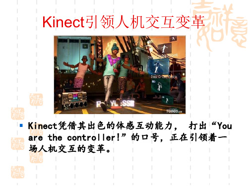
Kinect引领人机交互变革
▪ Kinect凭借其出色的体感互动能力, 打出“You are the controller!”的口号,正在引领着一 场人机交互的变革。
什么是Kinect?
Kinect是一个Xbox360外接的3D体感摄影机 (如上图)利用即时动态捕捉、影像辨识、麦克风 输入、语音辨识等功能让玩家摆脱传统游戏手柄 的束缚,通过自己的肢体控制游戏。
▪ 散斑具有高度随机性,随着距离变换图案,空间中任何 两处的散斑都是不同的图案,等于将整个空间加上了标 记,所以任何物体进入该空间、以及移动时,都可确切 纪录物体的位置。
基于Kinect的实时稳定的三维多手指跟踪算法
( S t a t e Ke y L a b o r a t o r y o f C AD & C G.Z h  ̄i a n g Un i v e r s i t y.Ha n g z h o u 3 1 0 0 5 8 )
De c . 2O1 3
基 于 Ki n e c t 的 实 时稳 定 的 三维 多手指 跟踪 算 法
晏 浩 ” , 张明敏” , 童 晶 ∞ , 潘志庚h 。
1 ’ ( 浙江大学 C AD & C G国家重点实验室 杭 州 3 1 0 0 5 8 )
。 ( 杭州师范大学数字媒体与人机交互研究中心
me t h o d b a s e d o n p i x e l c l a s s i f i c a t i o n t o g e t t h e 2 D f i n g e r t i p s .F i n a l l y , we s a mp l e o n t h e d e p t h ma p a r o u n d t h e d e t e c t e d f i n g e r t i p t o g e t t h e Z- v a l u e o f t h e f i n g e r t i p s a n d t h e n c o mb i n e t h e Ka l ma n f i l t e r a n d t h e c o n t i n u i t y b e t we e n f r a me s t o t r a c k t h e 3 D p o s i t i o n o f f i n g e r t i p s . Th e f i n g e r t i p d e t e c t i o n
教你开自己的3D照相馆 使用Xbox 360 Kinect体感扫描 开一家3D照相馆你也可以做到
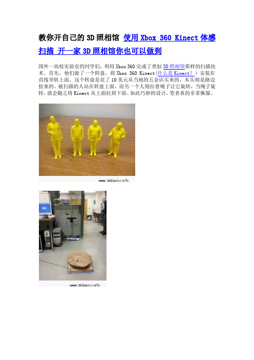
教你开自己的3D照相馆使用Xbox 360 Kinect体感扫描开一家3D照相馆你也可以做到
国外一高校实验室的同学们,利用Xbox 360完成了类似3D照相馆那样的扫描技术。
首先,他们做了一个转盘,将Xbox 360 Kinect(什么是Kinect?)安装在直线导轨上面。
这个转盘是花了10美元从当地的五金店买来的,木头则是路边捡来的。
被扫描的人站在转盘上面,而另一个人则拉着绳子让它旋转,当绳子旋转,就会随之将Kinect从上面拉到下面。
如此巧妙的设计,笔者真的非常佩服。
之后,他们使用Reconstructme软件,将数据从Kinect转换成3D模型。
再经过netfabb Studio软件简单处理就完成了。
提示:1.完成这个图形扫描需要独立显卡才能完成实时扫描计算
2.除了Xbox 360 Kinect,还可以使用ASUS Xtion做扫描
3.控制旋转速度,要慢,要顺畅
文章来源:,3D打印机智能网。
基于Kinect人体动态三维重建

基于Kinect人体动态三维重建
刘雷杰
【期刊名称】《电子产品世界》
【年(卷),期】2016(23)9
【摘要】从图像中恢复出三维物体表面模型的方法称为3D重构,是计算机图形学研究领域中一个重要的研究方向。
准确可靠的三维动态几何重建在影视制作和游戏开发中具有重要作用。
不同于静态物体表面三维重建,动态几何三维重建需要研究帧与帧之间准确的对应信息。
本文提出的方法基于单个Kinect硬件系统,利用Kinect重建出人体的静态三维模型,结合Kinect识别出的骨架进行人物的动态三维模型重建。
【总页数】4页(P35-37,41)
【作者】刘雷杰
【作者单位】天津大学电子信息工程学院天津 300010
【正文语种】中文
【相关文献】
1.基于Kinect的骨骼配准的人体三维重建 [J], 林瑞;王俊英;孙水发;董方敏
2.基于Kinect的人体实时三维重建及其应用 [J], 马旋;薛原;杨若瑜
3.基于Kinect的人体三维重建方法 [J], 李翔;李泽丰;李治江
4.基于Kinect的人体实时三维重建及其应用 [J], 农旭安;吴嘉仪;蔡晓文
5.基于Kinect的人体三维动作实时动态识别 [J], 胡新荣;王梦鸽;刘军平;彭涛
因版权原因,仅展示原文概要,查看原文内容请购买。
基于Kinect的3D人脸识别(1)

基于kinect的3D人脸识别技术摘要在2D人脸识别技术不断发展的今天,深度学习的出现让2D人脸识别技术的准确率已经达到了97.54%,2D技术的发展空间越来越小。
而随着3D技术也越来越成熟,将3D技术融合到人脸识别技术中是一种新的发展方向。
而现阶段,kinect这种体积轻巧,价格便宜,捕获3D数据效率高而且分辨率不低的设备成了许多研究人员的研究对象。
在本文中我们也利用了kinect设备完成了一个基于kinect的3D人脸识别研究的过程。
首先通过kinect设备采集了一批数据,接着实现了一种基于熵图和显著性图,利用HOG特征算子,和随机森林分类器和SVM分类器进行识别的算法系统。
通过我们的实验,利用随机森林分类器实现的分类器准确率只有73%,而利用SVM分类器达到的准确率有83.19%。
但是因为采集数据的范围小,以及算法的不完善性,我们的系统还有很大的提升空间。
关键词:kinect,RGB-D,显著性,熵图,随机森林,SVM,人脸识别AbstractWith the fast development of the face recognition based 2D data, the deep learning technology makes the accuracy of the face recognition based 2D data have reached in 97.54% and the development of the 2D technology in face recognition has reached the bottleneck. However, with the 3D technology becoming more and more mature, it is a new development direction to fuse the 3D technology into face recognitiontechnology. In the meanwhile, the Kinect which is portable, inexpensive and has high capturing rate and moderate definition becomes the research object of many researchers.In our paper, we used the Kinect equipment to finish a project which is about face recognition based 3D data. First of all, we collected enough RGB-D data using Kinect. Then we implemented the algorithm system which is based the entropy map and the visual saliency map, gets the feature vector using the HOG descriptor and using random decision forest and support vector machine to classify the data.The result of our experiment is not very well. The accuracy of the recognition with random decision forest classifier reaches only 73%. However, the accuracy of the recognition with support vector machine reaches 83.19%. Because of the small scale in the database and the imperfect algorithm, our system can still make great progress.Key words:Kinect, RGB-D, salience, entropy, RDF, SVM, face recognition1,绪论1.1研究背景随着人们对人工智能,机器学习算法的研究的不断深入,其分支领域中的计算机视觉中的人脸识别技术也得到了充分的发展和巨大的进步。
kinect fusion算法

kinect fusion算法摘要:1.函数式编程与事件绑定2.JavaScript 中的事件绑定3.事件代理和事件冒泡4.事件机制的优化5.结论正文:1.函数式编程与事件绑定在JavaScript 中,函数式编程是一种重要的编程范式,它强调无副作用的计算。
事件绑定是JavaScript 中的一种机制,用于将特定的事件与相应的处理函数关联起来。
函数式编程与事件绑定相结合,可以实现更简洁、可维护的代码。
2.JavaScript 中的事件绑定JavaScript 中的事件绑定主要通过addEventListener 方法实现。
该方法接受两个参数:一个是事件类型,例如"click"或"mouseover";另一个是处理函数,当事件发生时,该函数将被调用。
例如:```javascriptdocument.getElementById("btn").addEventListener("click", function() {console.log("按钮被点击");});```3.事件代理和事件冒泡事件代理是一种事件处理机制,它允许我们在一个父元素上处理子元素的事件。
这种机制可以提高事件处理效率,避免在每个子元素上绑定事件处理函数。
事件冒泡是指事件从触发元素开始,逐层向上级元素传播的过程。
通过事件冒泡,我们可以在父元素上处理子元素触发的事件。
例如,我们可以在父元素上使用addEventListener,通过事件代理处理子元素的点击事件:```javascriptdocument.getElementById("parent").addEventListener("click", function(e) {if (e.target.tagName === "BUTTON") {console.log("按钮被点击");}});```4.事件机制的优化在实际开发中,我们可能会遇到大量事件处理函数的情况。
基于Kinect的虚拟3D视频会议场景融合研究
势, 近年来发展迅速 , 应用广泛[ 1。 从视频会议 系统 逐渐被 普及 的时代 开始 , 产生 了基 于 专业 硬件设备 的视频 会议 系统 ( 如思科 等公 司生产 的视 频 会议设备 ) , 以及基 于 P C或 其他 非视 频会议 特 有设 备 , 以 软件 实现的视 频会议 系统( 如G o o g l e +等) 。前 者通 常视 频 效果 清晰 , 分辨率高 , 传输快 速稳定 , 但需要特 定的编码 、 解 码调制设 备 、 专有 网络 , 因而系统 实现成本较高 。后 者只需 要在 P C等 平 台上 , 通 过软件 来实 现编 、 解码 , 由公 用 网络 传输 数据 , 成本低廉 , 但 效果 视频会议效果 难以应用 于正式 场合 。 随着新型科技产 品的出现 , 网络视频 会议 的发展 出现
Abs t r a c t To bu i l d a n e w t y p e o f v i d e o c o n f e r e n c e mo d e wi t h 3 D c a me r a .t h e 3 D mo de l o f p a r t i c i p a t o r i s d i s t r a c t e d a n d f us e d i nt o v i r t u a l
CHENG Ho n g we i J I ANG Le t i a n
( El e c t r o n i c I n f o r ma t i o n a nd El e c t r i c a l En g i n e e r i n g,Sh a n g ha i J i a o t o n g Un i v e r s i t y S c h o o l ,S h a n g h a i 2 0 0 2 4 0 )
3D Mapping with an RGB-D Camera
3D Mapping with an RGB-D CameraFelix Endres,Jürgen Hess,Jürgen Sturm,Daniel Cremers,Wolfram Burgard Abstract—In this article we present a novel mapping systemthat robustly generates highly accurate3D maps using an RGB-Dcamera.Our approach does not require any further sensorsor odometry.With the availability of low-cost and light-weightRGB-D sensors such as the Microsoft Kinect,our approachapplies to small domestic robots such as vacuum cleaners aswell asflying robots such as quadrocopters.Furthermore,oursystem can also be used for free-hand reconstruction of detailed3D models.In addition to the system itself,we present athorough experimental evaluation on a publicly available bench-mark dataset.We analyze and discuss the influence of severalparameters such as the choice of the feature descriptor,thenumber of visual features,and validation methods.The results ofthe experiments demonstrate that our system can robustly dealwith challenging scenarios such as fast cameras motions andfeature-poor environments while being fast enough for onlineoperation.Our system is fully available as open-source and hasalready been widely adopted by the robotics community.Index Terms—RGB-D,Localization,Mapping,SLAM,Open-Source.I.I NTRODUCTIONT HE problem of simultaneous localization and mapping(SLAM)is one of the most actively studied problems inthe robotics community in the last decade.The availability of amap of the robot’s workspace is an important requirement forthe autonomous execution of several tasks including localiza-tion,planning,and navigation.Especially for mobile robotsworking in complex,dynamic environments,e.g.,fulfillingtransportation tasks on factoryfloors or in a hospital,it isimportant that they can quickly generate(and maintain)a3Dmap of their workspace using only onboard sensors.Manipulation robots,for example,require a detailed modelof their workspace for collision-free motion planning andaerial vehicles need detailed maps for localization and navi-gation.While previously many3D mapping approaches relied on expensive and heavy laser scanners,the commercial launch of RGB-D cameras based on structured light provided an attractive,powerful alternative.In this work,we describe one of thefirst RGB-D SLAM sys-tems that took advantage of the dense color and depth images provided by RGB-D pared to previous work,we introduce several extensions that aim at further increasing the robustness and accuracy.In particular,we propose the use of an environment measurement model(EMM)to validate the transformations estimated by feature correspondences and the iterative closest point(ICP)algorithm.In extensive experi-ments we show that our RGB-D SLAM system allows us to F.Endres,J.Hess,and W.Burgard are with the Department of Computer Science,University of Freiburg,Germany.J.Sturm and D.Cremers are with the Department of Computer Science,Technische Universität München, Germany.This work has partly been supported by the European Commission under the contract number FP7-ICT-248258-First-MM.Fig.1.Top:Occupancy voxel map of the PR2robot.V oxel resolution is 5mm.Occupied voxels are represented with color for easier viewing.Bottom row:A sample of the RGB input images.accurately track the robot pose over long trajectories and under challenging circumstances.To allow other researchers to use our software,reproduce the results,and improve on them,we released the presented system under an open-source license. The code and detailed installation instructions are available online[1].II.R ELATED W ORKWheeled robots often rely on2D laser range scanners, which commonly provide very accurate geometric measure-ments of the environment at high frequencies.To compute the relative motion between observations,most state-of-the-art SLAM(and also localization-only)systems use variants of the iterative-closest-point(ICP)algorithm[2],[3],[4].A variant particularly suited for man-made environments uses thepoint-to-line metric [5].Recent approaches demonstrate that the robot pose can be estimated at millimeter accuracy [6]using two laser range scanners and ICP.Disadvantages of ICP include the dependency on a good initial guess to avoid getting stuck in a local minimum and the lack of a measure of the overall quality of the match.Approaches that use planar localization and a movable laser range scanner,e.g.,on a mobile base with a pan-tilt unit or at the tip of a manipulator,allow for precise localization of a 2D sensor in 3D.In combination with an inertial measurement unit (IMU),this can also be used to create a map with a quadrocopter [7].Visual SLAM approaches [8],[9],[10],also referred to as “structure and motion estimation”[11],[12]compute the robot’s motion and the map using cameras as sensors.Stereo cameras are commonly used to gain sparse distance information from the disparity in textured areas of the re-spective images.In contrast to laser-based SLAM,Visual SLAM systems typically extract sparse keypoints from the camera images.Visual feature points have the advantage of being more distinctive than typical geometric structures,which simplifies data association.Popular general purpose keypoint detectors and descriptors include SIFT [13],SURF [14],and ORB [15].Descriptors can easily be combined with different keypoint detectors.In our experiments,we use the detector originally proposed for the descriptor.For SURF,the detection time strongly dominates the runtime,therefore we further analyzed the descriptor in combination with the keypoint detector proposed by Shi and Tomasi [16],which is much faster (though at the price of lower repeatability)than the detector proposed in [14].We compare the performance of the above descriptors in our SLAM system in Section IV-B.Recently introduced RGB-D cameras such as the Microsoft Kinect or the Asus Xtion Pro Live offer a valuable alternative to laser scanners,as they provide dense,high frequency depth information at a low price,size and weight.The depth sensor projects structured light in the infrared spectrum,which is perceived by an infrared camera with a small baseline.As structured light sensors are sensitive to illumination,they are generally not applicable in direct sunlight.Time-of-flight cam-eras are less sensitive to sunlight,but have lower resolutions,are more noisy,more difficult to calibrate,and much more expensive.The first scientifically published RGB-D SLAM system was proposed by Henry et al.[17]who use visual features in combination with GICP [18]to create and optimize a pose graph.Unfortunately neither the software nor the data used for evaluation have been made publicly available,so that a direct comparison cannot be carried out.KinectFusion [19]is an impressive approach for surface reconstruction based on a voxel grid containing the truncated signed distance [20]to the surface.Each measurement is di-rectly fused into the voxel representation.This reduces drift as compared to the frame-to-frame comparisons we employ,yet lacks the capability to recover from accumulating drift by loop closures.Real time performance is achieved,but requires high performance graphics hardware.The size of the voxel grid has cubic influence on the memory usage,so that KinectFusion only applies to small workspaces.Kintinuous [21]overcomesFig.2.Even under challenging conditions,a robot’s trajectory can be accurately reconstructed for long trajectories using our approach.The vertical deviations are within 20cm.(Sequence shown:“fr2/pioneer slam”)this limitation by virtually moving the voxel grid with the current camera pose.The parts that are shifted out of the reconstruction volume are triangulated.However,so far,the system cannot deal with loop closures and therefore may drift indefinitely.Our experiments show comparable quality in the trajectory estimation.Zeng et al.[22]show that the memory requirements of the voxel grid can be greatly reduced using an octree to store the distance values.Hu et al.[23]recently proposed a SLAM system that switches between bundle adjustment with and without available depth,which makes it more robust to lack of depth information,e.g.,due to distance limitations and sunlight.Our system has been one of the first SLAM systems specifically designed for Kinect-style sensors.In contrast to other RGB-D SLAM systems,we extensively evaluated the overall system [24],[25],and freely provide an open-source implementation to stimulate scientific comparison and progress.While many of the discussed approaches bear the potential to perform well,they are difficult to compare,be-cause the evaluation data is not available.Therefore,we ad-vocate the use of publicly available benchmarks and developed the TUM RGB-D benchmark [26]which provides several sequences with varying difficulty.It contains synchronized ground truth data for the sensor trajectory of each sequence,captured with a high precision motion capturing system.Each sequence consists of approx.500to 5,000RGB-D frames.III.A PPROACHA.System Architecture OverviewIn general,a graph-based SLAM system can be broken up into three modules [27],[28]:Frontend,backend and final map representation.The frontend processes the sensor data to extract geometric relationships,e.g.,between the robot andIEEE TRANSACTIONS3Feature Extraction Descriptors, 3D PositionsColorDescriptorStorageFig.3.Schematic overview of our approach.We extract visual features that we associate to3D points.Subsequently,we mutually register pairs of image frames and build a pose graph,that is optimized using g2o.Finally,we generate a textured voxel occupancy map using the OctoMapping approach.landmarks at different points in time.The frontend is specific to the sensor type used.Except for sensors that measure the motion itself as,e.g.,wheel encoders or IMUs,the robot’s motion needs to be computed from a sequence of observations. Depending on the sensor type there are different methods that can be applied to compute the motion in between two observations.In the case of an RGB-D camera the input is an RGB image I RGB and a depth image I D.We determine landmarks by extracting a high-dimensional descriptor vector d∈R64from I RGB and store them together with y∈R3, their location relative to the observation pose x∈R6.To deal with the inherent uncertainty introduced,e.g.,by sensor noise,the backend of the SLAM system constructs a graph that represents the geometric relations and their uncertainties.Optimization of this graph structure can be used to obtain a maximum likelihood solution for the represented robot trajectory.With the known trajectory we can project the sensor data into a common coordinate frame.However,in most applications a task-specific map representation is required,as using sensor data directly would be highly inefficient.We therefore create a three-dimensional probabilistic occupancy map from the RGB-D data,which can be efficiently used for navigation and manipulation tasks.A schematic representation of the presented system is shown in Figure3.The following sections describe the illustrated parts of the system.B.Egomotion EstimationThe frontend of our SLAM system uses the sensor input in form of landmark positions Y=y1,...,y n to compute geometric relations z ij which allow us to estimate the motion of the robot between state x i and x j.Visual features ease the data association for the landmarks by providing a measure for similarity.To match a pair of the keypoint descriptors (d i,d j)one computes their distance in the descriptor space. For SIFT and SURF the proposed distance is Euclidean. However,Arandjelovi´c and Zisserman[29]propose to use the Hellinger kernel to compare SIFT features.They report substantial performance improvements for object recognition. We implemented both distance measures and briefly discuss the impact on accuracy in Section IV-B.For ORB the Ham-ming distance is used.By itself,however,the distance is not a criterion for association as the distance of matching descriptors can vary greatly.Due to the high dimensionality of the feature space it is generally not feasible to learn a mapping for a rejection threshold.As proposed by Lowe,we resort to the ratio between the nearest neighbor and the second nearest neighbor in feature space.Under the assumption that a keypoint only matches to exactly one other keypoint in another image,the second nearest neighbor should be much further away.Thus,a threshold on the ratio between the distances of nearest and second nearest neighbor can be used effectively to control the ratio between false negatives and false positives.To be robust against false positive matches, we employ RANSAC[30]when estimating the transforma-tion between two frames,which proves to be very effective against individual mismatches.We quickly initialize a trans-formation estimate from three feature correspondences.The transformation is verified by computing the inliers using a thresholdθbased on the Mahalanobis distance between the corresponding features.For increased robustness in case of largely missing depth values,we also include features without depth reading into the verification.Particularly in case of few possible matches or many similar features,it is crucial to exploit the possible feature matches.We therefore threshold the matches at a permissive ratio.It has been highly beneficial to recursively reestimate the transformation with reducing thresholdθfor the inlier determination,as proposed by Chum et al.[31].Combined with a threshold for the minimum number of matching features for a valid estimate,this approach works well in many scenarios.For larger man-made environments the method is limited in its effectiveness,as these usually contain repetitive structures, e.g.,the same type of chair,window or repetitive wallpapers. Given enough similar features through such identical instances the corresponding feature matches between two images result in the estimation of a bogus transformation.The threshold on the minimum number of matches helps against random similarities and repetition of objects with few features but our experiments show that setting the threshold high enough to exclude estimates from systematic misassociations comes with a performance penalty in scenarios without the mentioned ambiguities.The alternative validation method proposed in Section III-C is therefore a highly beneficial extension.We use a least squares estimation method[32]in each20144fromstronglythetheEuclideanhas[17]insparseg2ooptimizeand thepreviously determined inliers.However,in our experiments,this additional optimization step shows only a slight improve-ment of the overall trajectory estimates.We also investigatedincluding the landmarks in the global graph optimization asit has been applied by other researchers.Contrary to ourexpectations we could only achieve minor improvements.Asthe number of landmarks is much higher than the number ofposes,the optimization runtime increases substantially.C.Environment Measurement ModelGiven a high percentage of inliers,the discussed methodsfor egomotion estimation can be assumed successful.However,a low percentage does not necessarily indicate an unsuccessfultransformation estimate and could be a consequence of lowoverlap between the frames or few visual features,e.g.,dueto motion blur,occlusions or lack of texture.Hence,both ICPand RANSAC using feature correspondences lack a reliablefailure detection.We therefore developed a method to verify a transformationestimate,independent of the estimation method used.Ourmethod exploits the availability of structured dense depth data,in particular the contained dense free-space information.Wepropose the use of a beam-based environment measurementmodel(EMM).An EMM can be used to penalize pose esti-mates under which the sensor measurements are improbablegiven the physical properties of the sensing process.In ourcase,we employ a beam model,to penalize transformationsfor which observed points of one depth image should havebeen occluded by a point of the other depth image.EMMs have been extensively researched in the context of2D Monte Carlo Localization and SLAM methods[33],wherethey are used to determine the likelihood of particles on thebasis of the current observation.Beam-based models havebeen mostly used for2D rangefinders such as laser rangescanners,where the range readings are evaluated using raycasting in the map.While this is typically done in a2Doccupancy grid map,a recent adaptation of such a beam-basedmodel for localization in3D voxel maps has been proposedby Oßwald et al.[34].Unfortunately,the EMM cannot betrivially adapted for our purpose.First,due to the size of theinput data,it is computationally expensive to compute evena partial3D voxel map in every time step.Second,sincea beam model only provides a probability density for eachbeam[33],we still need tofind a way to decide whetherto accept the transformation based on the observation.Theresulting probability density value obtained for each beam doesFig.4.Two cameras and their observations aligned by the estimatedtransformation T AB.In the projection from camera A to camera B,the dataassociation of y i and y j is counted as an inlier.The projection of y q cannotbe seen from Camera B,as it is occluded by y k.We assume each pointoccludes an area of one pixel.Projecting the points observed from cameraA to camera B,the association between y i and y j is counted as inlier.Incontrast,y p is counted as outlier,as it falls in the free space between cameraA and observation y q.The last observation,y k is outside of thefield of viewof camera A and therefore ignored.Hence,thefinal result of the EMM is2inliers,1outlier and1occluded.not constitute an absolute quality measure.Neither does theproduct of the densities of the individual beams.The value for,e.g.,a perfect match will differ depending on the range value.In Monte Carlo methods,the probability density is used asa likelihood value that determines the particle weight.In theresampling step,this weight is used as a comparative measureof quality between the particles.This is not applicable in ourcontext as we do not perform a comparison between severaltransformation candidates for one measurement.We thus need to compute an absolute quality measure.Wepropose to use a procedure analogous to statistical hypothesistesting.In our case the null hypothesis being tested is theassumption that after applying the transformation estimate,spatially corresponding depth measurements stem from thesame underlying surface location.To compute the spatial correspondences for an alignmentof two depth images I D and I D,we project the points y iof I D into I D to obtain the points y i(denoted without theprime).The image raster allows for a quick association to acorresponding depth reading y j.Since y j is given with respectto the sensor pose it implicitly represents a beam,as it containsinformation about free space,i.e.,the space between the originand the measurement.Points that do not project into the imagearea of I D or onto a pixel without valid depth reading areignored.For the considered points we model the measurement noiseaccording to the equations for the covariances given byKhoshelham and Elberink[35],from which we constructthe covariance matrixΣj for each point y j.The sensornoise for the points in the second depth image is representedaccordingly.To transform a covariance matrix of a point to thecoordinate frame of the other sensor pose,we rotate it usingR,the rotation matrix of the estimated transformation,i.e.,Σi =R T Σ i R .The probability for the observation y i given an observation y j from a second frame can be computed asp (y i |y j )=ηp (y i ,y j ),with η=p (y j )−1(1)Since the observations are independent given the true obstacle location z we can rewrite the right-hand side top (y i |y j )=ηp (y i ,y j |z )p (z )d z ,(2)=η p (y i |z )p (y j |z )p (z )d z ,(3)=η N (y i ;z ,Σi )N (y j ;z ,Σj )p (z )d z .(4)Exploiting the symmetry of Gaussians we can write=η N (z ;y i ,Σi )N (z ;y j ,Σj )p (z )d z(5)The product of the two normal distributions contained in the integral can be rewritten [36]so that we obtainp (y i |y j )=ηN (y i ;y j ,Σij )N (z ;y c ,ˆΣij )p (z )d z ,(6)where y c =(Σ−1i +Σ−1j )−1(Σ−1i y i +Σ−1j y j )−1,(7)Σij =Σi +Σj and ˆΣij =(Σ−1i +Σ−1j)−1(8)The first term in the integral in (6)is constant with respect toz ,which allows us to move it out of the integralp (y i |y j )=ηN (y i ;y j ,Σij )N (z ;y c ,ˆΣij )p (z )d z .(9)Since we have no prior knowledge about p (z )we assume it tobe a uniform distribution.As it is constant,the value of p (z )thus becomes independent of z and we can move it out of the integral.We will see below that the posterior distribution remains a proper distribution despite the choice of an improper prior [37].The remaining integral only contains the normal distribution over z and,by the definition of a probability density function,reduces to one,leaving onlyp (y i |y j )=ηN (y i ;y j ,Σij )p (z ).(10)Informally speaking,having no prior knowledge about the true obstacle also means we have no prior knowledge about the measurement.This can be shown by expanding the normal-ization factorη=p (y j )−1= p (y j |z )d z −1(11)= N (y j ;z ,Σj )p (z )d z −1(12)and using the same reasoning as above,we obtain p (y j )−1= p (z )N (z ;y j ,Σj )d z−1(13)=p (z )−1(14)Combining (14)and (10),we get the final resultp (y i |y j )=N (y i ;y j ,Σij )(15)We can combine the above three-dimensional distributionsof all data associations to a 3N -dimensional normal distribu-tion,where N is the number of data associations.Assuming independent measurements yieldsp (∆Y )=N (∆Y |0,Σ)∈R 3N ,(16)where ∆Y =(...,∆yij ,...) is a column vector contain-ing the N individual terms ∆y ij =y i −y j and Σcontains the corresponding covariance matrices Σij on the (block-)diagonal.Note that the above formulation contains no additional term for short readings as given in [33]since we expect a static environment during mapping and want to penalize this kind of range reading,as it is our main indication for misalignment.In contrast,range readings that are projected behind the corresponding depth value,are common,e.g.,when looking behind an obstacle from a different perspective.“Occluded outliers”,the points projected far behind the associated beam (e.g.,further than three standard deviations)are therefore ignored.However,we do want to use the positive information of “occluded inliers”,points projected closely behind the associated beam,which in practice confirm the transformation estimate.Care has to be taken when examining the statistical properties,as this effectively doubles the inliers.Figure 4illustrates the different cases of associated observations.A standard hypothesis test could then be used for rejecting a transformation estimate at a certain confidence level,by testing the p-value of the Mahalanobis distance for ∆Y for a χ23N distribution (a chi-square distribution with 3N degrees of freedom).In practice,however,this test is very sensitive to small errors in the transformation estimate and therefore hardly useful.Even under small misalignments,the outliers at depth jumps will be highly improbable under the given model and will lead to rejection.We therefore apply a measure that varies more smoothly with the error of the transformation.Analogously to robust statistics such as the median and the median absolute deviation,we use the hypothesis test on the distributions of the individual observations (15)and compute the fraction of outliers as a criterion to reject a transformation.Assuming a perfect alignment and independent measurements,the fraction of inliers within,e.g.,three standard deviations can be computed from the cumulative density function of the nor-mal distribution.The fraction of inliers is independent of the absolute value of the outliers and thus smoothly degenerates for increasing errors in the transformation while retaining an intuitive statistical meaning.In our experiments (Section IV-D)we show that applying a threshold on this fraction allows to effectively reduce highly erroneous transformation estimates that would greatly diminish the overall quality of the map.D.Visual Odometry and Loop Closure SearchApplying an egomotion estimation procedure,such as the one described in Section III-B,between consecutive frames provides visual odometry information.However,the indi-vidual estimations are noisy,particularly in situations with few features or when most features are far away,or even out of bining several motion estimates,by addi-tionally estimating the transformation to frames other thanFig.5.Pose graph for the sequence“fr1/floor”.Top:Transformation estimation to consecutive predecessors and randomly sampled frames.Bottom: Additional exploitation of previously found matches using the geodesic neighborhood.In both runs,the same overall number of candidate frames for frame-to-frame matching were processed.On the challenging“Robot SLAM”dataset,the average error is reduced by26%.the direct predecessor substantially increases accuracy and reduces the drift.Successful transformation estimates to much earlier frames,i.e.,loop closures,may drastically reduce the accumulating error.Naturally,this increases the computational expense linearly with the number of estimates.For multi-core processors,this is mitigated to a certain degree,since the individual frame-to-frame estimates are independent and can therefore be parallelized.However,a comparison of a new frame to all predecessor frames is not feasible and the possibility of estimating a valid transformation is strongly limited by the overlap of thefield of view,the repeatability of the keypoint detector and the robustness of the keypoint descriptor.Therefore,we require a more efficient strategy for selecting candidate frames for which to estimate the transformation. Recognition of images in large sets of images has been inves-tigated mostly in the context of image retrieval systems[38] but also for large scale SLAM[39].While these methods may be required for datasets spanning hundreds of kilome-ters,they require an offline training step to build efficient data structures.Due to the sensor limitations,we focus on indoor applications and proposed an efficient,straightforward to implement algorithm to suggest candidates for frame-to-frame matching[25].We employ a strategy with three different types of candidates.Firstly,we apply the egomotion estimation to n immediate predecessors.To efficiently reduce the drift, we secondly search for loop closures in the geodesic(graph-) neighborhood of the previous frame.We compute a minimal spanning tree of limited depth from the pose graph,with the sequential predecessor as root node.We then remove the n immediate predecessors from the tree to avoid duplication and randomly draw k frames from the tree with a bias towards earlier frames.We therefore guide the search for potentially successful estimates by those previously found.In particular, when the robot revisits a place,once a loop closures is found this procedure exploits the knowledge about the loop by preferring candidates near the loop closure in the sampling. Tofind large loop closures we randomly sample l frames from a set of designated keyframes.A frame is added to the set of keyframes,when it cannot be matched to the previous keyframe.In this way,the number of frames for sampling is greatly reduced,while thefield of view of the frames in between keyframes always overlaps with at least one keyframe.Figure5shows a comparison between a pose graph con-structed without and with sampling of the geodesic neighbor-hood.The extension of found loop closures is clearly visible. The top graph has been created by matching n=3immediate predecessors and k=6randomly sampled keyframes.The bottom graph has been created with n=2,k=5and l=2sampled frames from the geodesic neighborhood.Table I exemplary states the parameterization for a subset of our experiments.The choice of these parameters is crucial for the performance of the system.For short,feature-rich sequences low values can be set,as done for"fr1/desk".For longer sequences the values need to be increased.E.Graph OptimizationThe pairwise transformation estimates between sensor poses,as computed by the SLAM frontend,form the edges of a pose graph.Due to estimation errors,the edges form no globally consistent trajectory.To compute a globally consistent trajectory we optimize the pose graph using the g2o frame-work[40],which performs a minimization of a non-linear error function that can be represented as a graph.More precisely, we minimize an error function of the formF(X)=i,j ∈Ce(x i,x j,z ij) Ωij e(x i,x j,z ij)(17)tofind the optimal trajectory X∗=argmin X F(X).Here, X=(x 1,...,x n) is a vector of sensor poses.Further-more,the terms z ij andΩij represent respectively the mean and the information matrix of a constraint relating the poses x i and x j,i.e.,the pairwise transformation computed by the frontend.Finally,e(x i,x j,z ij)is a vector error function that measures how well the poses x i and x j satisfy the constraint z ij.It is0when x i and x j perfectly match the constraint, i.e.,the difference of the poses exactly matches the estimated transformation.Global optimization is especially beneficial in case of large loop closures,i.e.,when revisiting known parts of the map, since the loop closing edges in the graph diminish the accumu-lated error.Unfortunately,large errors in the motion estimation step can impede the accuracy of large parts of the graph.This is primarily a problem in areas of systematic misassociation of features, e.g.,due to repeated occurrences of objects. For challenging data where several bogus transformations are found,the trajectory estimate obtained after graph optimization may be highly distorted.The validation method proposed in Section III-C substantially improves the rate of faulty trans-formation estimates.However,the validity of transformations。
一种基于Kinect的实时虚拟人动画生成方法
一种基于Kinect的实时虚拟人动画生成方法杨道谈【摘要】针对传统的虚拟人动画生成存在的实时性差、逼真度低、动画生成复杂、成本高等问题,提出了一种基于Kinect体感捕捉设备的实时虚拟人动画生成方法.利用正向运动学方法建立具有拓扑骨架结构的虚拟人模型,将Kinect读取到的用户骨骼信息代入正向运动学方程进行求解,并重定向到虚拟人模型,驱动模型做出真实的一致性运动.为了消除虚拟人运动中的悬浮、穿透和部分关节点丢失现象,提出了平移补偿和关节点丢失保持机制.实验结果表明,该方法能实时逼真的驱动虚拟人运动并生成动画,且该方法易于实现、实用性强.【期刊名称】《电子科技》【年(卷),期】2015(028)007【总页数】4页(P149-152)【关键词】虚拟人;Kinect;运动重定向;正向运动学【作者】杨道谈【作者单位】杭州电子科技大学图形图像研究所,浙江杭州310018【正文语种】中文【中图分类】TP391.41所谓运动重定向是对运动数据的重用方式之一,其可提供动画制作中后期调整的可能性以及解决无法模拟但是又需要逼真效果的高难度动作问题。
运动重定位技术[1]解决的核心问题是,如何在将原始模型的运动轨迹信息映射到目标模型上的同时,保持动作的逼真性和一致同步性。
国内外的专家学者对虚拟人动画技术进行了大量研究,Waters 等人对虚拟人的建模和特定动作进行了的研究,提出了用虚拟网格来模拟虚拟人从而实现重定向[2]。
Badler 等人则利用参数化的关键帧技术在进行运动底层控制同时,提出了将虚拟人骨骼化以便减少计算复杂的方法[3]。
Hodgins 则研究跳水、跳马等体育动作的动态仿真技术[4]。
Gleicher 等人提出将B 样条曲线引入关节点运动方程求解中,从而在时空约束条件下得出全局最优解以提高目标模型的运动逼真性[5]。
Rama 等采用图像处理中的边缘检测算法来检测原始模型视频运动中的重大变化[6],同时利用约束下的逆向运动学(IK)求解方程,以防止目标模型的失真。
基于Unity3D与Kinect的体感交互技术应用研究
基于Unity3D与Kinect的体感交互技术应用研究基于Unity3D与Kinect的体感交互技术应用研究近年来,人机交互技术在游戏、教育和医疗等领域中的应用逐渐受到关注。
随着虚拟现实技术的不断发展和普及,基于体感交互的技术也逐渐成为一种热门形式。
本文将探讨基于Unity3D与Kinect的体感交互技术应用研究。
一、引言体感交互是一种通过人体的动作和动态姿态来与计算机进行交互的技术。
它不仅可以提供更加自然和直观的交互方式,还可以增强用户的沉浸感和参与感。
其中,Unity3D是一款跨平台的游戏引擎,广泛应用于游戏开发、可视化设计等领域;而Kinect是微软研发的一种基于深度摄像头和红外线投射器的体感设备,能够实时捕捉和识别人体骨骼和动作。
二、Unity3D与Kinect的结合Unity3D与Kinect的结合可以实现更加真实和直观的人机交互体验。
通过Kinect设备,Unity3D可以实时捕捉用户的动作和姿态,并将其转化为游戏或应用中的控制命令。
同时,Unity3D还可以利用Kinect的深度信息和图像识别技术,实现更加精准的交互响应和环境感知。
三、体感交互技术在游戏领域中的应用基于Unity3D与Kinect的体感交互技术在游戏领域中有着广泛的应用。
例如,可以借助Kinect设备实时捕捉玩家的动作,然后在Unity3D中进行运算和渲染,实现真实的游戏角色动作。
通过体感交互技术,游戏可以更加刺激和有趣,玩家可以通过身体的运动参与游戏,极大地增强了游戏的娱乐性和沉浸感。
四、体感交互技术在教育领域中的应用基于Unity3D与Kinect的体感交互技术在教育领域中也有着潜在的应用价值。
例如,可以开发一款体感交互的虚拟实验室,让学生通过身体的动作和操作来进行实验操作,从而增加学习的趣味性和参与度。
此外,还可以开发一款体感交互的教育游戏,通过身体的运动和操作来进行学习和知识的巩固,激发学生的学习积极性。
五、体感交互技术在医疗领域中的应用体感交互技术在医疗领域中也有着广阔的应用前景。
- 1、下载文档前请自行甄别文档内容的完整性,平台不提供额外的编辑、内容补充、找答案等附加服务。
- 2、"仅部分预览"的文档,不可在线预览部分如存在完整性等问题,可反馈申请退款(可完整预览的文档不适用该条件!)。
- 3、如文档侵犯您的权益,请联系客服反馈,我们会尽快为您处理(人工客服工作时间:9:00-18:30)。
Copyright is held by the author / owner(s).
SIGGRAPH 2011, Vancouver, British Columbia, Canada, August 7 – 11, 2011.
ISBN 978-1-4503-0921-9/11/0008
KinectFusion:Real-TimeDynamic3DSurfaceReconstructionandInteraction
ShahramIzadi1,RichardA.Newcombe1,2,DavidKim1,OtmarHilliges1,DavidMolyneaux1,
SteveHodges1,PushmeetKohli1,JamieShotton1,AndrewJ.Davison2,AndrewFitzgibbon
1
1MicrosoftResearch∗,2ImperialCollegeLondon†
Figure1:Weintroduceanewsystemforacquiringhigh-quality,geometricallyprecise3Dmodelsofanentireroomrapidlyusingasingle
movingKinectcamera.Thesystemgenerateshigh-qualitymodelsfromnoisyKinectdatainreal-time.Anentireroomorsmallerobjectscan
bereconstructedinseconds(topsequences).Wedemonstrateanumberofcompellingnewinteractivepossibilitiessuchasmulti-touchonany
arbitrarilyshapedsurface(bottomleftsequence);real-timerigidbodyphysicssimulatedonadynamicreconstructedmodel(bottommiddle
sequence);andrapidsegmentationandtrackingofobjectswithinthemodel(bottomrightsequence).
1Introduction
WepresentKinectFusion,asystemthattakeslivedepthdatafrom
amovingKinectcameraandinreal-timecreateshigh-quality,ge-
ometricallyaccurate,3Dmodels.Oursystemallowsauserhold-
ingaKinectcameratomovequicklywithinanyindoorspace,and
rapidlyscanandcreateafused3Dmodelofthewholeroomand
itscontentswithinseconds.Evensmallmotions,causedforexam-
plebycamerashake,leadtonewviewpointsofthesceneandthus
refinementsofthe3Dmodel,similartotheeffectofimagesuper-
resolution.Asthecameraismovedclosertoobjectsinthescene
moredetailcanbeaddedtotheacquired3Dmodel.
Toachievethis,oursystemcontinuallytracksthe6DOFposeofthe
cameraandrapidlybuildsarepresentationofthegeometryofarbi-
trarysurfaces.NovelGPU-basedimplementationsforbothcamera
trackingandsurfacereconstructionallowustorunatinteractive
real-timeratesthathavenotpreviouslybeendemonstrated.We
definenewinstantiationsoftwowellknowngraphicsalgorithms
designedspecificallyforparallelizableGPGPUhardware.
2KinectFusion
ThemainsystempipelinefirsttakesthelivedepthmapfromKinect
andconvertsfromimagecoordinatesinto3Dpointsandnormals
inthecoordinatespaceofthecamera.Nextthetrackingphase
computesarigid6DOFtransformthatcloselyalignsthecurrent
orientedpointswiththepreviousframes,usinganovelGPUim-
plementationoftheICPalgorithm[BeslandMcKay1992].This
definesarelativerigidtransformfromthepreviouscameraposeto
thecurrent.Thesetransformsareincrementallyappliedtoaglobal
transformthatdefinestheglobalposeofthecamera.Giventhe
∗
{shahrami,b-davidk,otmarh,a-davmo,shodges,pkohli,jamiesho,awf}
@microsoft.com
†
{rnewcombe,ajd}@doc.ic.ac.uk
globalposeofthecamera,pointsandnormalsareconvertedinto
globalcoordinates,andasingleconsistent3Dmodelisupdated.
Insteadofsimplyfusingpointclouds,wereconstructsurfacesbased
onanovelGPU-basedimplementationofvolumetrictruncated
signeddistancefunctions[CurlessandLevoy1996].Voxelswithin
thevolumeareupdatedbasedonourgloballyconvertedmeasure-
ments.Eachvoxelstoresarunningaverageofitsdistancetothe
assumedpositionofaphysicalsurface.FinallyweuseGPUaccel-
eratedraycastingtorenderaviewofthevolumeandthe3Dsurfaces
itcontainsgiventhecurrentglobalposeofthecamera.Theview
ofthevolumeequatestoasyntheticdepthmap,whichcanbeused
asalessnoisymoregloballyconsistentbaseorreferenceframe
forthenextiterationofICPtracking.Thisallowsustotrackby
comparingthecurrentlivedepthmapwithourlessnoisyraycasted
viewofthemodel,asopposedtousingonlythelivedepthmaps
frame-to-frame.
Thesystemcanreconstructascenewithinsecondsandenablesin-
teractivepossibilitiesincluding:extendingmulti-touchinteractions
toanyarbitrarilyshapedreconstructedsurface;advancedfeatures
foraugmentedreality;real-timephysicsthataresimulatedliveon
thedynamicmodel;andnovelmethodsforsegmentationandtrack-
ingofscannedobjects.WealsopresentextensionstoourGPU-
basedtrackingalgorithmtodistinguishscenemotionfromcamera
motionthusdealingwithdynamicscenes,inparticularoneswhere
usersareinteracting.SeeFigure1andaccompanyingvideofor
examples.
References
BESL,P.,ANDMCKAY,N.1992.Amethodforregistrationof3D
shapes.239–256.
CURLESS,B.,ANDLEVOY,M.1996.Avolumetricmethodfor
buildingcomplexmodelsfromrangeimages.InACMTransac-
tionsonGraphics(SIGGRAPH).