[VIP专享]兰州交通大学电子元器件市场调研
吉林大学仪器科学与电气工程学院_企业报告(业主版)

1.3.1 规模结构 近 1 年吉林大学仪器科学与电气工程学院的项目规模主要分布于小于 10 万区间,占项目总数的 54.3%。 500 万以上大额项目 0 个。 近 1 年(2022-09~2023-08):
本报告于 2023 年 08 月 23 日 生成
2/22
1.4 行业分布
企业基本信息
单位名称: 营业范围:
吉林大学仪器科学与电气工程学院
一、采购需求
1.1 总体指标
近 1 年(2022-09~2023-08):
项目数(个)
92
同比增长:155.6%
项目总金额(万元)
(不含费率与未公示金额)
¥1211.85
同比增长:108.3%
平均金额(万元)
¥13.17
同比增长:-18.5%
吉林省晟富瑞鑫科 技有限公司
7.0
TOP8
[BA202201739] 电 机 配 套 器 件 备 案公示公告
吉林省晟富瑞鑫科 技有限公司
7.0
TOP9
[BA202300211] 光 学 组 件 备 案 公 示公告
北京波威科技有限 公司
5.2
2022-12-06 2022-12-03 2023-04-04
中标单位
中标金额(万元) 公告时间
TOP2
[BA202201100]CMOS 探 测 器 备 案公示公告
开普勒(宁波)光电 技术有限公司
15.0
TOP3
[BA202300390]JF-YD-3104 力 传 感器
朝阳区明悦教学仪 器销售部
15.0
TOP4
[BA202300876]SQUID 磁传感器 备案公示公告
基于Proteus的单片机虚拟仿真实验案例设计

基于Proteus的单片机虚拟仿真实验案例设计谭筠梅;李玉龙;王履程【摘要】A new experimental teaching method based on the actual engineering case-driven teaching is put forward,and an experiment case of the overweight system of the SCM truck based on Proteus simulation is designed.This case brings together all the knowledge points of the SCM experimental course and emphasizes the cultivation of the students'ability of the software and hardware system integration and engineering practical ability.The students'interest in learning has been greatly improved,and the good experimental teaching effect has been achieved.%提出采用实际工程案例驱动教学的实验教学新方法.设计了基于Proteus仿真的单片机货车超重监控系统的实验案例,案例汇聚了单片机实验课程的各个知识点,着重培养学生软硬件系统集成能力和工程实践能力,大大地提高了学生的学习兴趣,取得了良好的实验教学效果.【期刊名称】《实验技术与管理》【年(卷),期】2018(035)005【总页数】4页(P122-125)【关键词】单片机;Proteus;实验案例;实践教学【作者】谭筠梅;李玉龙;王履程【作者单位】兰州交通大学国家级计算机实验教学示范中心,甘肃兰州 730070;兰州交通大学国家级计算机实验教学示范中心,甘肃兰州 730070;兰州交通大学电子与信息工程学院,甘肃兰州 730070【正文语种】中文【中图分类】TP391.9;G642单片机嵌入式系统类课程是各电类专业普遍开设的计算机硬件类课程。
有机半导体NTCDA的合成及结构表征

应芳香环内c—H键的振动模式;1579.47cm~, 1512.69cm-。,1487.74cm~,1437.63cm。1处的峰位 均为芳香环骨架的特征振动吸收模式;1579. 47cm。1特征峰的出现说明分子中芳香环的共轭作 用很强,即整个环上的电子轨道相互作用后呈订键 的性质。根据上述分析,样品具有环状酸酐的性质, 而且分子中含有芳香环。
1.2 NTCDA的提纯
1.2.1萃取提纯 利用萘四甲酸易溶于甲醇而萘二甲酸不溶于甲
醇的特性,可以萃取分离提纯NTcDA。萃取分离是 利用溶剂把固体中的杂质分离出来从而实现物质提 纯的方法。分离萃取器提纯原理如图2所示。提取 前,将滤纸卷成筒状,其直径略小于提取筒的内径, 一端用线扎紧或将滤纸卷成一段封口的杯状即底端 要封好。将要提纯的样品装入纸筒,放入萃取室中。 烧杯中加入有机溶剂和1~2粒沸石,I●l▲ 虮∞o.N,
jl。。。.。.
10 9 8 7 6 5 4 3 2 1 —0 ppm
Fig.4 Nuclear magnetic resonance spectmm of NTCDA
图4 NTcDA核磁共振谱
F培.5 M01ecule stnlcture of NTCDA 图5 NTcDA的分子结构
第13卷第6期 2007年12月
功能材料与器件学报 JOURNAL 0F FUNC7n0NAL MATERIALS AND DEVICES
文章编号:1007—4252(2007)06一0630—05
V01.13.No_6 Dec..2007
有机半导体NTCDA的合成及结构表征
李建丰,孙硕,董茂军,胥超,肖剑,张福甲
O引言
有机半导体是一类新型半导体材料,有机半导 体材料相对于无机半导体材料,具有价廉质轻、溶解 性好、可通过分子剪裁调控光电性能、在材料制备和 薄膜制备上具有灵活多变的技术特点可实现非晶态 柔性衬底的大面积化,进而有望大大降低半导体电 子元器件的制造成本。这些特性使有机半导体材料
L4960单片开关电源设计
设计斩波式变换器。
关键词:开关电源;DC/DC变换器;单片开关集成稳压器;IA960
中图分类号:TP368.1
文献标识码:B
文章编号:1004—373X(2007)12—029—03
A Design of L4960 Single Chip Switching Power Supply
ZHENG Yaotian (Hanshan Teachers College,Chaozhou,521041,China)
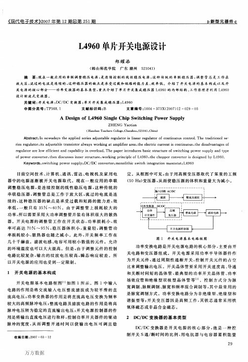
源,其电源效率可达90%以上。由于他把开关电源所需 要的基准电压源ቤተ መጻሕፍቲ ባይዱ锯齿波发生器、脉宽调制器、功率输出级 (即开关功率管)和各种保护电路全部集成在同一芯片中, 实现了单片集成化。
单片开关式集成稳压器的主要生产厂家是意一法半导 体有限公司。该公司于20世纪80年代中期首先推出了 第一代产品有:IA960,L4962,1.296,L4964。在20世纪90 年代又开发出的第二代产品包括:L4970/I。4970A,1.4972/ 4972A/4972AD,IA974/4974A,IA975/4975A,L4977/ 4977A。上述产品中以1.4970和IA970A的输出功率为最 大,最大输出电流为10 A,输出功率可达400 W。
L4960单片开关电源设计
郑耀添
(韩山师范学院广东潮州
521041)
摘 要:现在一般应用的串联调整稳压电源,是连续控制的线性稳压电源,这种传统的串联稳压器,调整管总是工作在
放大区,流过的电流是连续的,这种稳压器的缺点是承受过载和短路的能力差、效率低。介绍了开关电源的基本构成以及开 关电源的核心部分——功率变换器的基本类型,重点介绍了单片开关集成稳压器L4960的内部结构、工作原理并利用1.4960
电子通信中常见干扰因素及控制措施

^mmmm2021年第05期(总第221期)电子通信中常见干扰因素及控制措施招继恩(杰创智能科技股份有限公司,广东广州510663)摘要:随着社会发展和经济水平的提升,人们的生活逐渐实现了现代化、智能化,尤其电子通信技术的应用完全改变了传 统信息传递的方式,电子通信主要是指建立在网络技术基础上进行信息传递和交换的技术。
随着我国进入新时代,经济 实现了稳定增长,各行各业对于电子通信的依赖程度和应用范围不断提升。
随着大量现代化科学技术的应用,电子通信 也受到了一些干扰因素的影响,电子通信所产生干扰的因素和控制措施也就成为了目前业内所重点研究的课题。
文章 首先介绍电子通信的概念,再阐述电子通信抗干扰的重要性,最后,结合电子通信干扰控制要素谈一谈电子通信干扰的 有效控制措施。
关键词:电子通信;常见干扰因素;控制分析中图分类号:TN975 文献标识码:A文章编号:2096-9759(2021)05-0078-04〇引言电子通信技术的快速发展使得人们的生活方式和生产方 式产生了翻天覆地的变化,尤其在国民经济发展和社会建设 当中起到了至关重要的作用,甚至在军事领域,对于电子通 讯的应用也改变了现代战争的模式,但由于电子通信技术具 有一定的特殊性,这也就意味着电子通信容易受到一些因素 的干扰影响,需要采取一定的抗干扰措施,提高电子通信的质量。
1关于电子通信电子通信主要是指依靠网络来实现信息传递和交换的技 术,目前较为具有代表性的是无线局域网,其能够实现信息的 快速传递和实时传递。
随着互联网技术覆盖范围的不断扩大, 电子通信技术的应用也越加广泛,且逐渐成为了人们生产生 活当中不可缺少的重要组成部分。
收稿日期=2021-03-12作者简介:招继恩(1977-),男,广东广州人,本科,杰创智能科技股份有限公司技术总工,主要从事信息化和通信技术研宄。
3结语本文通过设计一种实时检测方法,针对铁路信号智能电源屏电路故障问题加以解决。
【2018-2019】西南交通大学 电子市场调查报告 (3000字)word版本 (12页)
【2018-2019】西南交通大学 电子市场调查报告 (3000字)word版本 本文部分内容来自网络整理,本司不为其真实性负责,如有异议或侵权请及时联系,本司将立即删除! == 本文为word格式,下载后可方便编辑和修改! ==
西南交通大学 电子市场调查报告 (3000字) 西 南 交 通 大 学 电 气 工 程 学 院 子调 路 实 与 计 算 机 践 报 告 201X年 5 月 电 电 查 实践地点: 1. 成都市城隍庙电子电器市场。 2. 成都市磨子桥电脑一条街。 3. 电气学院计算机中心。
实践内容: 1. 了解电阻器、电容器、电感器、继电器、开关按钮、电压表、电流表、万用表等电子元器件的型号、规格、性能、用途、形状、价格。
2. 了解二极管、三极管、场效应管、晶闸管、晶体管、集成电路等电子元件的型号、规格、性能、用途、形状、价格。
3. 了解计算机硬件的组成 (硬盘、内存、显卡、显示器、键盘、光区、鼠标等),了解计算机的型号、不同用途的计算机的配置和价格等。
电 阻 器 电阻(Resistor)是所有电子电路中使用最多的元件。电阻的主要物理特征是变电能为热能,也可说它是一个耗能元件,电流经过它就产生热能。电阻在电路中通常起分压分流的作用,对信号来说,交流与直流信号都可以通过电阻。 电阻器的分类方法比较多,但一般可以按照三种方式分类:
a.按阻值特性:固定电阻、可调电阻、特种电阻(敏感电阻: 热敏、光敏、压敏、湿敏气敏力敏等。).不能调节的,我们称之为固定电阻,而可以调节的,我们称之为可调电阻.常见的例如收音机音量调节的,主要应用于电压分配的,我们称之为电位器. b.按制造材料:碳膜电阻、金属膜电阻、线绕电阻等. C.按安装方式: 插件电阻、贴片电阻. 根据不同种类电阻器,据调查情况列表如下: 【2018-2019】西南交通大学 电子市场调查报告 (3000字)word版本 另有型号规格价格表如下: 电容器 电容器(capacitor)。电子设备中充当整流器的平滑滤波、电源和退耦、交流信号的旁路、交直流电路的交流耦合等的电子元件称为电容器。电容是电子设备中大量使用的电子元件之一,广泛应用于隔直,耦合,旁路,滤波,调谐回路, 能量转换,控制电路等方面。 电容器的分类
Experimental investigation and numerical simulation for weakening the thermal fluctuations Tjunction
Experimental investigation and numerical simulation for weakening the thermal fluctuations in aT-junctionK.Gao a ,P.Wang b ,T.Lu a ,⇑,T.Song caCollege of Mechanical and Electrical Engineering,Beijing University of Chemical Technology,Beijing 100029,China bSchool of Energy and Power Engineering,Dalian University of Technology,Dalian 116024,China cChina Nuclear Power Technology Research Institute Co.,Ltd,Shenzhen 518124,Chinaa r t i c l e i n f o Article history:Received 25August 2014Received in revised form 17November 2014Accepted 4January 2015Available online 17January 2015Keywords:Experimental investigation Numerical simulation Tee junctionThermal fluctuationa b s t r a c tIn this work,the mixing processes of hot and cold fluids with and without a distributor are predicted by experiments and numerical simulations using large-eddy simulation (LES)on FLUENT platform.Temperatures at different positions of the internal wall and mixing conditions caused by T-junctions at different times are obtained,then the simulated normalized mean and root-mean square (RMS)temperature,velocity vector and temperature contour for the two structures,namely with and without a distributor,are compared.The results show that,compared with the a T-junction without a distributor,the mixing region of hot and cold water in the T-junction with distributor moves to the middle of the pipe,and the inclusion of the distributor reduces the temperature fluctuations of internal wall noticeably and makes the mixing of hot and cold water more efficient.Ó2015Elsevier Ltd.All rights reserved.1.IntroductionTee junction is a familiar structure that is universally used in pipeline systems of power plants,nuclear power plants and chemi-cal plants,it is often applied to mix hot and cold fluid of main and branch pipes.The fluctuations of fluid temperature are transported to the solid walls by heat convection and conduction.This can cause cyclical thermal stresses and subsequent thermal fatigue cracking of the piping (Lee et al.,2009).So far,leakage accidents took place in several light water and sodium cooled reactors due to thermal fati-gue.In 1998,a crack was discovered at a mixing tee in which cold water from a branch pipe flowed into the main pipe in the residual heat removal (RHR)system in a reactor in Civaux,France.Metallur-gical studies concluded that the crack was caused by a high degree of cycle thermal fatigue (Eric Blondet,2002).In 1990,sodium leak-age happened in the French reactor Superphenix (Ricard and Sperandio,1996).It has been established that mixing hot and cold sodium can induce temperature fluctuations and result in thermal fatigue (IAEA,2002).Therefore,it is significant to study how to weaken thermal fatigue of the piping wall to ensure the integrity and safety of the piping system in a nuclear power plant.In the analysis of thermal fatigue,temperature fluctuation is a very important evaluation parameter.A reliable lifetime assess-ment of these components is difficult because usually only thenominal temperature differences between the hot and cold fluids are known,whereas the instantaneous temperatures and heat fluxes at the surface are unknown (Paffumi et al.,2013).Kamaya and Nakamura (2011)used the transient temperature obtained by simulation to assess the distribution of thermal stress and fati-gue when cold fluid flowed into the main pipe from a branch pipe.Numerical simulation of flow in the tee has been carried out Simoneau et al.(2010)to get temperature and its fluctuation curves,and the numerical results were in good agreement with the experimental data.Through the analysis on thermal fatigue stress,it draw the conclusion that the enhanced heat transfer coef-ficient and the temperature difference between hot and cold fluids were primary factors of thermal fatigue failure of tees.Many numerical simulations and experiments have been carried out to evaluate the flow and heat transfer in a mixing tee junction (Metzner and Wilke,2005;Hu and Kazimi,2006;Hosseini et al.,2008;Durve et al.,2010;Frank et al.,2010;Jayaraju et al.,2010;Galpin and Simoneau,2011;Aulery et al.,2012;Cao et al.,2012).Turbulent models such as Reynolds-averaged Navier–Stokes (RANS),Unsteady Reynolds averaged Navier Stokes (URANS),Scale-Adaptive Simulation (SAS),Reynolds stress model (RSM),detached eddy simulations (DES),and LES have all been used in industrial applications.As one of the choices of turbulent model for predicting the mixing flow in tee junctions,the RSM can bemused to describe the momentum conservation of the mixing (Durve et al.,2010;Frank et al.,2010).Turbulent mixing phenomena in a T-junction have been numerically investigated using the k $x/10.1016/j.anucene.2015.01.0010306-4549/Ó2015Elsevier Ltd.All rights reserved.Corresponding author.based baseline Reynolds stress model(BSL RSM)(Frank et al.,2010) for two different cases.Durve et al.(2010)applied the RSM to pre-dict the velocityfield of three non-isothermal parallel jetsflowing in an experiment setup used to simulate theflow occurring at the core outlet region of a fast breeder reactor(FBR),with a Reynolds number of1.5Â104.Theflow in tube of different Reynolds numbers (Re)andflow velocity ratio were studied experimentally with three-dimensional scanning using particle image velocimetry(3D-SPIV) (Brücker,1997).Large-eddy simulation(LES)is an alternative turbulence model with different subgridscale models often employed to predict velocity and temperaturefluctuations.Indeed many numerical studies have shown the capability of LES to model thermalfluctu-ations in turbulent mixing.LES was performed(Lee et al.,2009)to analyze temperaturefluctuation in the tee junction and the simu-lated results were in good agreement with the experimental data. Thermal striping phenomena in the tee junction had been numer-ically investigated using LES(Hu and Kazimi,2006)for two differ-ent mixing cases,and the simulated normalized mean and root-mean square(RMS)was consistent with experimental results. LES in a mixing tee were carried out(Galpin and Simoneau, 2011)in order to evaluate the sensitivity of numerical results to the subgrid scale model by comparing the experimental results, and to investigate the possibility of reducing thefluid computa-tional domain at the inlet.Another simulation that mixing of a hot and a coldfluid stream in a vertical tee junction with an upstream elbow main pipe was carried out with LES(Lu et al., 2013).And the numerical results show that the normalized RMS temperature and velocity decrease with the increases of the elbow curvature ratio and dimensionless distance.In the meantime,many scholars have studied how to weaken the thermalfluctuation.Experiments and simulation were con-ducted(Wu et al.,2003)on a tee junction geometry with a sleeve tube in it.Theflow is divided into three types of jets by theflow velocity ratio in main and branch pipes.Through the analysis of flowfield and velocityfield of various jets types,it indicate that the addition of sleeve tube relieve the thermal shock caused by the coldfluid injection rge-eddy simulation have been used(Lu et al.,2010)to evaluate the thermal striping phe-nomena in tee junctions with periodic porous media,the temper-ature and velocityfield inside the tubes are obtained.The research revealed that the addition of a porous reduces the tem-perature and velocityfluctuations in the mixing tube.As mentioned above,experiments and numerical simulations for both tee junction geometry with a sleeve tube in it(Wu et al., 2003)and for a mixing tee with periodic porous media in it(Lu et al.,2010)have been carried out.The results of previous researches provide a good reference value for this work that anal-yses the role of distributor in weakening the thermalfluctuation of internal piping wall,and this structure has not been studied to date,to the best of our knowledge.In this work,mixing processes have been studied by the experiment and numerically predicted with LES.Then the simulated normalized mean and root-mean square(RMS)temperature,velocity vector and temperature con-tour of the two tees are compared.2.Experiment systemThe Experimentflowchart is presented in Fig.1.The experimen-tal system consists of four main components,a cold water supply line,a hot water supply line,a test section,and a data acquisition unit.The experiment device is shown in Fig.2.Experimentfluid was adjusted to the desired temperature by the heater and chiller, and then was pumped to the test section.After mixing thefluid is returned to the heater for recycling,some of the excessfluid is dis-charged through the overflow pipe.During the mixing of thefluids, the temperature of the mixingfluid is collected and recorded by the thermocouple probe installed on the tube wall.The experiment requires two different structures of the test sec-tion,Fig.3is the T-junction section without the branch liquid dis-tributor and Fig.4is that with the branch liquid distributor.The addition of this structure has two main functions:(1)changing the mixing position of hot and coldfluids:moving the mixing zone to the middle of the tube,and away from the main pipe wall;(2) increasing the intensity of mixing process:adding the fence near the outlet of distributor enhanced the mixed disturbance and the exacerbatedfluid mixing of the inner tube.For the convenience of observing and adjusting the mixing process,the test section is a round pipe made of plexiglass,and other pipes are made of steel. Fig.5is the physical model of the branch liquid distributor.The test conditions in the present experiment are shown in Table1.We collected the instantaneous temperature data of every measurement points by the data collector.The distribution of sam-pling points are shown in Fig.6,there are total eight thermocou-ples in the circumferential direction at each plane.In the T-junction section without the branch liquid distributor,the number of the collected plane is6(x/d m=1,2,3,4,6,8).That is to say there are48thermocouples in the structure without distributor.And in the T-junction section with the branch liquid distributor,the num-ber of the collected plane is5(x/d m=2,3,4,6,8),which means there are40thermocouples in the structure that with the distrib-utor.In both structures,the distance between measuring point the thermocouple probe and the inner wall is30mm.Since the collect-ing frequency of the collector is limited,we use1Hz as the collect-ing frequency after theflowfield is stable,and the total number of collection is800s.Table1shows the specific parameters of the test conditions.NomenclatureT time(s)Pr Prandtl numberLs mixing length of subgrid grid(m)T temperature(K)G acceleration of gravity(m/s2)K von Karman numberCs Smagorinsky numberS ij subgrid strain rate tensorM R momentum ratio of main pipe and branch pipe TÃnormalized mean temperaturesTÃrms normalized RMS temperaturesR d diameter ratioR v velocity ratiox,y,z axial coordinate(m)Greek symbolsqfluid density(kg/m3)b coefficient of thermal expansionl viscosity(Pa s)ltturbulent viscosity(Pa s)k thermal conductivity(w/(m k))C P heat capacity(J/(kg°C))K.Gao et al./Annals of Nuclear Energy78(2015)180–187181182K.Gao et al./Annals of Nuclear Energy78(2015)180–1871\4\11-thermometers 2\5\10-pressure gauge 3\9-flow meter 6-c ooler 7-heater8-overflow 12-test sec tion 13-thermoc ouple data c ollec torFig.1.Experimentflow chart.Fig.5.Physical model of the branch liquid distributor(a)the whole graph(b)theprofile map.Fig.2.Experiment device of thermalfluctuation.Fig.3.Schematic diagram of the T-junction section without the branch liquid distributor.Fig.4.Schematic diagram of the T-junction section with the branch liquid distributor.3.Numerical simulationFig.7is the numerical model based on the experimental section of T junction.The size of the model,boundary conditions are con-sistent with the experiment.In which,hot water enters from the left of main pipe,and cold water enters from the branch pipe,finally the mixingfluidflow out of the right of the main pipe.Dur-ing the calculation,the steady results offlowfield and heat transfer are obtained by Reynolds stress model(RSM)firstly,and then set @q@tþ@q u i@x i¼0ð1Þ@q u i@tþ@q u i u j@x j¼À@ p@x iÀq0bðTÀT0Þgþ@@x jlþltÀÁ@ u i@x jþ@ u j@x i!ð2Þ@q T@tþ@q Tu j@x j¼@@x jkc p@T@x jÀq T00u00j!ð3ÞIn these equations,q,b,l,l t,k and c p represent the density,ther-mal expansion coefficient,molecular viscosity,turbulent viscosity, thermal conductivity and specific heat capacity,respectively.The Smagorinsky–Lilly model is used for the turbulent viscosity,which is described as:lt¼q L2s j S jð4Þj S jTable1Experimental conditions.Main pipe Branch pipeFlow rate (m3/h)Temperature(K)Flow rate(m3/h)Temperature(K)Without distributor0.645304.650.270287.65With distributor0.645304.650.266287.65Fig.6.The distribution of sampling points on the planes.Physical model of T-junction(a)without the branch liquid distributor;(b)with the branch liquid distributor.K.Gao et al./Annals of Nuclear Energy78(2015)180–187183ij ¼12@ u i@x jþ@ u j@x ið7Þwhere k is the Von Karman constant of0.42;d is the distance to the closest wall;C s is the Smagorinsky constant of0.1;V is the volume of the computational cell.4.Results and discussionThe normalized mean and root-mean square temperature are used to describe the time-averaged temperature and temperature fluctuation intensity.The normalized temperature is defined as:ü1NX Ni¼1TÃið8ÞN is the total number of sample times.TÃi¼T iÀT cT hÀT cð9Þwhere T i is the transient temperature,T c is the coldfluid inlet tem-perature and T h is hotfluid inlet temperature.The root-mean square(RMS)of the normalized temperature is defined as:TÃrms¼ffiffiffiffiffiffiffiffiffiffiffiffiffiffiffiffiffiffiffiffiffiffiffiffiffiffiffiffiffiffiffiffiffiffiffiffiffiffiffiffi1X Ni¼1TÃiÀTÃ2rð10Þ184K.Gao et al./Annals of Nuclear Energy78(2015)180–187parison of experimental and numerical resultsAs can be seen from the Fig.8,the numerical normalized mean temperature distributions at the plane x/d m=1and the plane x/ d m=2are in good qualitative agreement and in adequate quantita-tive agreement,and most of them are within the experimental deviation of±20%.Meanwhile,the lifting trends of the data are the same.In the direction of180°,the mean temperatures are both minimal.And with the angle decrease to0°,the temperatures are gradually increased.Quantitative differences between the experi-ment and numerical results are that the normalized mean temper-atures given by LES are larger than the experimental data.That is because we did not add insulation unit on tube wall in the exper-iment,leading the transfer of some heat into the air.And in the process of numerical simulation,we ignored the convective heat transfer between the wall and the air.As shown in Fig.9,although the numerical results and experi-mental results have a little difference at the plane x/dm=2around the location of225°and the plane x/dm=2around the location of 0°and315°,all of them are within the error range that can be accepted.Both the simulations and experimental results give a lar-ger mean temperature in the top half of the main pipe than in the bottom half.This verifies the validity of the LES model for predict-ing the mixing of hot and coldfluids in a tee junction.The normalized RMS temperature on the plane x/d m=1and plane x/d m=2are shown in Fig.10,respectively.Similar to the nor-malized mean temperature,the normalized RMS temperature lines agree very well with the experiment ones.Both of the maximum values appear at the bottom half of the pipe.This indicates that the maximum temperaturefluctuations of main pipe appear on the opposite of the branch pipe inlet in this condition.As shown in Fig.11,the numerical results and the experimental results have the same trend and the numerical data are agreed well with the experimental ones.By comparison with Figs.4and5,dif-ferent from the temperaturefluctuations distribution which with-out the branch liquid distributor,there are two peaks of high fluctuation located at the90°and270°directions along with the tube.This is because the direction is that of the outlet of branch liquid distributor,the coldfluidflowing out from the outlet of branch liquid distributor mixes very fast with the hotfluid,leading to dramatic changes of temperature.In summary,the LES simulation results obtained are generally in good qualitative and quantitative agreement with the experi-mental data for the case of T-junction with/without the branch liquid distributor.Based on this,we analyzed the numerical results further.And the results are reported in the section below.4.2.Numerical results with/without branch liquid distributorThe numerical data were sampled on the inner wall in the plane x/ d m=À1,À0.5,0,0.5,1,2,3,4,6and8.At the same time,the numer-ical data were sampled from points every5mm along the intersec-tional lines of planes of y/d m=0and sections of x/d m=À2,À1,0,1,2, 3,4,5and6,to get the points with the maximum normalized rootK.Gao et al./Annals of Nuclear Energy78(2015)180–187185mean square temperatures in the tee and on the top and bottom walls.Here,the temperature and velocityfields were determined with LES simulations for the case of tee junction with/without branch liquid distributor.The temperature contours and velocity vectors for the T-junction are shown in Figs.12and13,respectively.As can be seen in Fig.12,due to the large branch pipeflow velocity,hot and coldfluid mixing zone is mainly located in both upstream and downstream region of the intersections of the main pipe and the branch pipe.The vigorous mixing offluids in the tube leads to thermalfluctuation on the wall.But in the T-junction with the branch liquid distributor,the mixing region moves to the lower half and downstream region of the main pipe.This indicates that the distributor is advantageous to weaken thermalfluctuations on the wall.The same conclusion can be seen from Fig.13,the dis-tributor weaken thermalfluctuations on the wall of downstream region and the top of the main pipe.186K.Gao et al./Annals of Nuclear Energy78(2015)180–187Fig.14compares the normalized mean temperatures between two tees of different structures.As can be seen,wall temperature changes great in the direction of90°,135°,225°and270°in T-junc-tion with the distributor,because the directions are the distributor outlet directions.This indicates that the coldfluid mixes with hot fluid on the wall afterflows out of the distributor.At the same time,the temperature in the direction of180°also changes dra-matically.That is because the coldfluid moves down in the effects of gravity and buoyancy.As shown in Fig.15,for the tee with distributor,the maximum values of normalized RMS temperature are smaller than that of the tee without distributor in most directions.This indicates that the adding of the distributor can relieve thermalfluctuations on the wall to some extent.And for the T-junction with distributor,tem-perature tends to be stable after the plane of x/d m=6,which indi-cates that twofluids have made a full mixing,while for the initial tee,temperature is still in the dramatic change,and this shows that the improved structure can effectively reduce the mixing length.Fig.16shows the maximum normalized instantaneous temper-aturefluctuations in the tee and on the top and bottom walls in the plane y/d m=0.In the tee,the maximum normalized instantaneous temperaturefluctuations of the case without distributor vary from 0.45to0.8,which means that the hot and coldfluids alternate in this location.However,for the case with distributor,the tempera-turefluctuations in the tee as well as on the top and bottom walls are much smaller than those of the case without distributor.That also implies that the distributor can reduce the temperaturefluctu-ation effectively.The normalized instantaneous temperaturefluctuations cannot describe the relationship between power spectrum density(PSD) and frequency of the temperaturefluctuation.PSD against fre-quency is one of the most important parameter for thermal fatigue analysis,which can directly show how PSD is in a certain fre-quency.The PSDs of the points with maximum temperaturefluctu-ation for the cases with and without distributor against frequency were recorded by fast Fourier transform(FFT)and shown in Fig.17. The temperaturefluctuation of the case without distributor has the highest PSD,at the frequency of0.04Hz,whereas the distributor significantly reduces the PSD of the temperaturefluctuations with the frequency from0.01to0.1Hz.In addition,the PSD of temper-aturefluctuations decreases with the frequency increasing.5.ConclusionsAs thermal stratification can result in thermal fatigue in the pip-ing system of a nuclear power plant,safety and integrity evaluation of the piping system has become an important issue.In this work the temperaturefluctuation has been studied by the experiment and numerically predicted by LES for two types of vertical tee junc-tion:one with distributor in the branch pipe and another without. The numerical results of normalized mean and RMS temperatures for the two structures have been found to be in good qualitative and quantitative agreement with the experimental data,which val-idates the use of LES simulations to evaluate convective mixing in such geometries.At the same time,the simulated normalized mean and root-mean square(RMS)temperature,velocity vector and temperature contour of the two tees are compared.The numerical results show that thefluctuations of temperatures of the tee without the distrib-utor are larger than those of the tee with the distributor,which can be explained by the branch liquid distributor enhancing the mix-ing.Although both tees give the same momentum ratio between the main pipeflow and the branch pipeflow,mixing and convec-tive heat transfer are greatly enhanced by the presence of the branch liquid distributor.These all show that the structure is effec-tive for weakening the thermalfluctuation of tee piping wall when hot and coldfluids mix,and it can make the mixing more sufficient.AcknowledgementsThis work was supported by projects of the National Natural Science Foundation of China(No.51276009),Program for New Century Excellent Talents in University(No.NCET-13-0651),and the National Basic Research Program of China(No.2011CB706900). ReferencesAulery, F.,Toutant, A.,Monod,R.,Brillant,G.,Bataille, F.,2012.Numerical simulations of sodium mixing in a T-junction.Appl.Therm.Eng.37,38–43.Brücker,C.,1997.Study of the three-dimensionalflow in a T-junction using a dual-scanning method for three-dimensional scanning-particle-image velocimetry (3-D SPIV).Exp.Therm.Fluid Sci.14,35–44.Cao,Q.,Lu,D.,Lv,J.,2012.Numerical investigation on temperaturefluctuation of the parallel triple-jet.Nucl.Eng.Des.249,82–89.Durve,A.,Patwardhan,A.W.,Banarjee,I.,Padmakumar,G.,Vaidyanathan,G.,2010.Thermal striping in triple jetflow.Nucl.Eng.Des.240,3421–3434.Eric Blondet, C.F.,2002.High cycle thermal fatigue in french PWR.In:10th International Conference on Nuclear Engineering.Arlington,Virginia,USA,pp.429–436.Frank,T.,Lifante,C.,Prasser,H.M.,Menter,F.,2010.Simulation of turbulent and thermal mixing in T-junctions using URANS and scale-resolving turbulence models in ANSYS CFX.Nucl.Eng.Des.240,2313–2328.Galpin,J.,Simoneau,J.P.,rge Eddy Simulation of a thermal mixing tee in order to assess the thermal fatigue.Int.J.Heat Fluid Flow32,539–545. Hosseini,S.M.,Yuki,K.,Hashizume,H.,2008.Classification of turbulent jets in a T-junction area with a90-deg bend upstream.Int.J.Heat Mass Transfer51,2444–2454.Hu,L.-W.,Kazimi,M.S.,2006.LES benchmark study of high cycle temperature fluctuations caused by thermal striping in a mixing tee.Int.J.Heat Fluid Flow 27,54–64.IAEA,2002.Validation of Fast Reactor Thermomechanical and Thermohydraulic Codes,Vienna.Jayaraju,S.T.,Komen,E.M.J.,Baglietto,E.,2010.Suitability of wall-functions in Large Eddy Simulation for thermal fatigue in a T-junction.Nucl.Eng.Des.240,2544–2554.Kamaya,M.,Nakamura, A.,2011.Thermal stress analysis for fatigue damage evaluation at a mixing tee.Nucl.Eng.Des.241,2674–2687.Lee,J.I.,Hu,L.-W.,Saha,P.,Kazimi,M.S.,2009.Numerical analysis of thermal striping induced high cycle thermal fatigue in a mixing tee.Nucl.Eng.Des.239, 833–839.Lu,T.,Jiang,P.X.,Guo,Z.J.,Zhang,Y.W.,Li,H.,rge-eddy simulations(LES)of temperaturefluctuations in a mixing tee with/without a porous medium.Int.J.Heat Mass Transfer53,4458–4466.Lu,T.,Liu,S.M.,Attinger,D.,rge-eddy simulations of structure effects of an upstream elbow main pipe on hot and coldfluids mixing in a vertical tee junction.Ann.Nucl.Energy60,420–431.Metzner,K.J.,Wilke,U.,2005.European THERFAT project—thermal fatigue evaluation of piping system‘‘Tee’’-connections.Nucl.Eng.Des.235,473–484. Paffumi, E.,Radu,V.,Nilsson,K.F.,2013.Thermal fatigue striping damage assessment from simple screening criterion to spectrum loading approach.Int.J.Fatigue53,92–104.Ricard,J.B.,Sperandio,M.,1996.Fracture mechanics applied to superphenix reactor components.Int.J.Pressure Vessels Piping65,295–301.Simoneau,J.-P.,Champigny,J.,Gelineau,O.,2010.Applications of large eddy simulations in nuclearfield.Nucl.Eng.Des.240,429–439.Wu,H.L.,Peng,X.F.,Chen,T.K.,2003.Influence of sleeve tube on theflow and heat transfer behavior at a T-junction.Int.J.Heat Mass Transfer46,2637–2644.K.Gao et al./Annals of Nuclear Energy78(2015)180–187187。
兰州市公安局交通警察支队_企业报告(业主版)
TOP7
兰州市公安局交通警察支队交通 甘肃佳誉科技贸易 事故现场防闯入预警系统及便携 有限公司
26.4
式警示屏采购项目成交公告
TOP8
兰州市公安局交通警察支队 2023 年电动车号牌购置项目成交公告
温州圣鸽标牌有限 公司
11.9
2023-08-07 2023-03-08
TOP9
兰州市公安局交通警察支队驾驶 甘肃顺驰贸易有限 证及行驶证证夹购置项目(第二 责任公司
兰州市公安局交通警察支队文创 宣传产品定制项目成交公告
甘肃鸿腾文化传媒 有限公司
中国邮政集团有限 公司兰州市安宁区 分公司
197.0 149.2 137.1 26.1 17.6
2023-05-12 2023-05-10 2023-05-10 2023-06-07 2022-09-19
本报告于 2023 年 08 月 22 日 生成
企业基本信息
单位名称: 营业范围:
兰州市公安局交通警察支队 未公示
一、采购需求
1.1 总体指标
近 1 年(2022-09~2023-08):
项目数(个)
79
同比增长:-16.0%
项目总金额(万元)
(不含费率与未公示金额)
¥6217.08
同比增长:-44.3%
平均金额(万元)
¥86.35
同比增长:-30.4%
6.0
次)成交结果公告
2023-05-09
TOP10
兰州市公安局交警支队机动车驾 兰州正通机动车驾 驶人社会化考试场(摩托车类) 驶员考试培训中心
\
服务采购项目三次成交公示
*按近 1 年项目金额排序,最多展示前 10 记录。
2023-01-17
西安交通大学_企业报告(供应商版)
- 1、下载文档前请自行甄别文档内容的完整性,平台不提供额外的编辑、内容补充、找答案等附加服务。
- 2、"仅部分预览"的文档,不可在线预览部分如存在完整性等问题,可反馈申请退款(可完整预览的文档不适用该条件!)。
- 3、如文档侵犯您的权益,请联系客服反馈,我们会尽快为您处理(人工客服工作时间:9:00-18:30)。
电子元器件调研与系统设计报告
考勤(10)守纪(10)报告(30)作品(30)答辩(20)总成绩(100)
专 业: 电气工程及其自动化
班 级: 电气XXXX
姓 名: XXX
学 号: XXXXXXX
指导教师: XXXXX
兰州交通大学自动化与电气工程学院
2013 年7月10日
1 题目
直流稳压电源设计。
2 设计目的
1) 加强直流稳压电源的工作原理的的理解。
2) 熟练掌握变压器、稳压芯片以及二极管的应用。
3 设计任务
利用变压器、二极管、电容、7812稳压芯片和7805稳压芯片制作一个输出
+12V和+5V的直流稳压电源。
4 市场调研
1) 直流稳压电源在生活中有广泛的应用。
2) 制作直流稳压电源所需要的元器件在市场上容易采购到。
5 功能
本次设计制作的直流稳压电源可以输出+12V和+5V的直流电,在生活中可
用于手机充电器、直流电继电器等。
6 方案
6.1 技术路线
变压器、桥式整流电路、电容滤波电路和集成稳压器稳压电路组成的直流稳
压电源。
6.2 关键技术
桥式整流、电容滤波、稳压器稳压。
7 电路原理图
7.1 桥式整流电路
在稳压电源中一般用四个二极管组成桥式整流电路,整流电路的作用是将交
流电压变换成脉动的直流电压。
负载电阻两端的输出电压和输出电流的平均值分别为
U
0
=(U为变压器负载端电压)sin22120Uππ)(ttd
==0.9U (1)U2
2
π
I
0
=0.9 (2)
R
U
流过每个二极管的平均电流为I的一半即
I=0.45 (3)
R
U
整流桥电路如图1所示。
TR1
TRAN-2P2S
BR1
2W005G
TR1(P1)
R
图1 整流桥电路图
7.2电容滤波电路
在桥式整流电路中,为了减少输出电压的脉动,可以在负载电阻的两端并联
一个滤波电容C。充放电时间常数越大,电荷改变的越慢,电容上的电压变化也
越慢,即交流分量就越小。输出的直流电压受负载变化的影响比较大,即外特性
差,是电容滤波电路的一个主要缺点。在电容C选定之后,负载电阻减小时,相
当于滤波电容的放电时间常数减小,电容C放电变快,因而使负载电压波形的平
直性变差,输出直流电压降低。所以电容滤波只适用于负载电流比较小或者负载
电流基本不变的场合。
在有电容滤波的整流电路中,要对其输出直流电压进行准确的计算是很困难
的,工程上一般按经验公式进行估算
U
1
=(1.1~1.4)U
(4)
滤波电容的的放电时间常数应满足
(5)2)5~3(TRC
其中:R为整流滤波电路的负载电阻,它为电容C提供放电通路。T = 20ms是
50Hz交流电压的周期。
整流滤波电路如图2所示。
TR1
TRAN-2P2S
BR1
2W005G
TR1(P1)
C
R
图2 整流滤波电路
7.3 稳压电路
由于输入电压发生波动、负载和温度发生变化时,滤波电路输出的直流电压
会随着变化。因此,为了维持输出电压稳定不变,还需加一级稳压电路。稳压电
路的作用是当外界因素(电网电压、负载、环境温度)发生变化时,能使输出直
流电压不受影响,而维持稳定的输出。稳压电路一般采用集成稳压器和一些外围
元件所组成。采用集成稳压器设计的稳压电源具有性能稳定、结构简单等优点。
三端稳压器的典型接法如图3所示。
VI1VO
3
G
N
D
2
U1
7805
C10.33uFC20.1uFC3
10uF
图3 三端稳压器的典型接法
7.4 实验电路图
直流稳压电源电路图如图4所示。
BR1
2W005G
TR1(P1)
VI1VO
3
G
N
D
2
U1
7812
VI1VO
3
G
N
D
2
U2
7805
C12200uC2220uC310uC42200uC50.33uC60.1uTR1TRAN-2P3SC7
220u
C8
10u
图4 直流稳压电源电路图
8 元器件清单
元器件清单如表1所示。
表1 元件清单
9 电路调试
直流稳压源+5V输出调试图如图5所示。
元器件名称 规格型号数量(个)单价(元)调研地点
变压器 双15变压器110西北电子商贸城
2200u耐压50v电解电容 24西北电子商贸城
220uf 电解
电容23西北电子商贸城10uf电解电容22西北电子商贸城0.33uf瓷片电容11西北电子商贸城电容
0.1uf瓷片电容11西北电子商贸城
781213
西北电子商贸城稳压芯片
780513
西北电子商贸城
电烙铁、焊锡 1 西北电子商贸城
电线插头 1 1 西北电子商贸城
导线若干 12 西北电子商贸城
万用板 1 9.0 西北电子商贸城
图5 +5V输出调试图
直流稳压源+12V输出调试图如图6所示。
图6 +12V输出调试图
10 总结
我们所做成的直流稳压电源,总共由四部分组成:变压器、整流电路、滤波
电路和稳压电路。从理解每一个部分的作用,到初次设计电路图,然后在proteus
软件上进行仿真,最后不断的改进,最终完成了电路设计。随后又进行了元器件
的采购,市场调研,组装,调试到最后的成品。在此过程中我体会到了团队合作
的重要性,光靠一个人的努力是远远不够的,需要大家的一起努力。同时也感觉
到了一些看起来很难的东西,在理解了它的原理之后,能变得很简单,同时认识
到了理论知识的重要性。
本次市场调研让我们了解到了社会的复杂性与多样性,感觉到了心目中的理
想与社会现实之间的距离。从这一点看,市场调查使我们受益无穷,可以说,它
是我到目前为止在大学里学到的最好的一门课程。我们经常说“学以致用”,从
这次市场调查的过程来看,如果说我们以前上课所学的课程全是理论课,那么市
场调查纯粹将理论与实践相结合为一体,并且在一定程度上也将其他理论课一同
付诸于实践,真正做到了学以致用。这几天的调研让我们以一个大学生的角度去
体验社会,以社会的角度来看待大学生。对于我们学生,只有真正接触到社会这
所真正的大学后,才能够有真正的感触。社会交往、工作并不是我们凭空想象的
那么容易,它是一个极其复杂的系统。我们的天真,我们的无知在社会面前应该
收敛了。面对社会,它则告诫我们,我们还很嫩,需要的路还走很长,需要更多
的实践与考验,这样才有可能成为一名真正的合格的社会工作者。
但由于水平有限,本次课程设计中存在一些误差,还望老师批评指正。
11 作品图片
作品俯视图如图7所示。
图7 作品俯视图
作品仰视图如图8所示。
7
图8 作品仰视图
参考文献
1.封志宏. 模拟电子技术[M]. 兰州:兰州大学出版社, 2003
2.付家才. 电子实验与实践[M]. 北京:高等教育出版社, 2004