Optical Properties of Selected Elements
偏振器的物理意义及圆偏振器的Jo_省略_es矩阵_评_关于圆偏振器_一文_蔡履中
a -i b =1 , c -i d =-i , a +i b =0 , c +i d =0
(5)
由此容易解得 :
a
=
1 2
,
b
=2i
,
c
=-2i
,
d
=12
(6)
故右旋圆偏振器的 Jones 矩阵为
J R =12
1 -i
i 1
(7)
它对本征矢 E R 的本征值为 1 , 对 E L本征值为 0 .
同理可得左旋圆偏振器的 Jones 矩阵为
[ 3] 郁道 银 , 谈恒 英 .工 程光 学[ M] .北 京 :机 械工 业 出版 社 , 1999.345.
[ 4] 梁铨 廷 .物 理光 学[ M] .北 京 :机 械工 业出 版社 , 1980 . 33 0 .
[ 5] 姚启 钧 .光 学教 程[ M] .北 京 :人 民教 育出 版社 , 1981 . 32 7 .
参考文献 :
[ 1] 王敦纯 , 曹俊卿 .关于圆偏振器[ J] .大学 物理 , 2004, 23 (1):33 ~ 34 .
[ 2] Hecht E , Zajac A .Optics[ M] .Reading , M assachusetts : Addison-Wesley , 1974 .266~ 271 .
1001 1
1
结果仍是右旋圆偏振光且强度不变 ;反之 , 若以右旋
圆偏振器作用于左旋圆偏振光 , 则会得到
10 0 1
12
00 0 0 00 0 0
10 0 1
1
0
0 =0
0
0
-1
0
(12)
这进一步表明了前文所述圆偏振器意义的正确性 .
国际物理林匹克竞赛试题Exp

PLANCK’S CONSTANT IN THE LIGHT OF AN INCANDESCENT LAMPIn 1900 Planck introduced the hypothesis that light is emitted by matter in the form of quanta of energy hν. In 1905 Einstein extended this idea proposing that once emitted, the energy quantum remains intact as a quantum of light (that later received the name photon). Ordinary light is composed of an enormous number of photons on each wave front. They remain masked in the wave, just as individual atoms are in bulk matter, but h – the Planck’s constant – reveals their presence. The purpose of this experiment is to measure Planck's constant.A body not only emits, it can also absorb radiation arriving from outside.Black body is the name given to a body that can absorb all radiation incident upon it,for any wavelength. It is a full radiator. Referring to electromagnetic radiation, black bodies absorb everything, reflect nothing, and emit everything. Real bodies are not completely black; the ratio between the energy emitted by a body and the one that would be emitted by a black body at the same temperature, is called emissivity, ε, usually depending on the wavelength.Planck found that the power density radiated by a body at absolutetemperature T in the form of electromagnetic radiation of wavelength λ can be written as()1/512-=T c e c u λλλε(1)where c 1 and c 2 are constants. In this question we ask you to determine c 2 experimentally, which is proportional to h .For emission at small λ, far at left of the maxima in Figure F-1, it is permissible to drop the -1 from the denominator of Eq. (1), that reduces to/512T c ec u λλλε=(2)The basic elements of this experimental question are sketched in Fig. F-2.∙ The emitter body is the tungsten filament of an incandescent lamp A that emits a wide range of λ’s, and whose luminosity can be varied.∙ The test tube B contains a liquid filter that only transmits a thin band of the visible spectrum around a value λ0 (see Fig. F-3). More information on the filter properties will be found in page 5.∙ Finally, the transmitted radiation falls upon a photo resistor C (also known as LDR, the acronym of Light Dependent Resistor). Some properties of the LDR will be described in page 6.The LDR resistance R depends on its illumination, E, which is proportional to the filament power energy density00E u R u R E λγλγ--∝⎫⎪⇒∝⎬∝⎪⎭where the dimensionless parameter γ is a property of the LDR that will be determined in the experiment. For this setup we finally obtain a relation between the LDR resistance R and the filament temperature TT c e c R 02/3λγ= (3)that we will use in page 6. In this relation c 3 is an unknown proportionality constant. By measuring R as a function on T one can obtain c 2, the objective of this experimental question. F-3DESCRIPTION OF THE APPARATUSThe components of the apparatus are shown in Fig. F-4, which also includes some indications for its setup. Check now that all the components are available, but refrain for making any manipulation on them until reading the instructions in the next page.EQUIPMENT:1.Platform. It has a disk on the top that holds a support for the LDR, a support for the tube and a support for anelectric lamp of 12 V, 0.1 A.2.Protecting cover.3.10 turns and 1 kΩ potentiometer.4.12 V battery.5.Red and black wires with plugs at both ends to connect platform to potentiometer.6.Red and black wires with plugs at one end and sockets for the battery at the other end.7.Multimeter to work as ohmmeter.8.Multimeter to work as voltmeter.9.Multimeter to work as ammeter.10.Test tube with liquid filter.11.Stand for the test tube.12.Grey filter.13.Ruler.An abridged set of instructions for the use of multimeters, along with information on the least squares method, isSETTING UP THE EQUIPMENTFollow these instructions:∙Carefully make the electric connections as indicated in Fig. F-4, but do not plug the wires 6 to the potentiometer.∙By looking at Fig. F-5, follow the steps indicated below:F-51.Turn the potentiometer knob anticlockwise until reaching the end.2.Turn slowly the support for the test tube so that one of the lateral holes is in front of the lamp and the other infront of the LDR.3.Bring the LDR nearer to the test tube support until making a light touch with its lateral hole. It is advisable toorient the LDR surface as indicated in Fig. F-5.4.Insert the test tube into its support.5.Put the cover onto the platform to protect from the outside light. Be sure to keep the LDR in total darkness forat least 10 minutes before starting the measurements of its resistance. This is a cautionary step, as theresistance value at darkness is not reached instantaneously.Task 1Draw in Answer Sheet 1 the complete electric circuits in the boxes and between the boxes, when the circuit is fully connected. Please, take into account the indications contained in Fig. F-4 to make the drawings.Measurement of the filament temperatureThe electric resistance R B of a conducting filament can be given asSlR B ρ=(4)where ρ is the resistivity of the conductor, l is the length and S the cross section of the filament.This resistance depends on the temperature due to different causes such as:∙ Metal resistivity increases with temperature. For tungsten and for temperatures in the range 300 K to 3655 K, itcan be given by the empirical expression, valid in SI units,83.081005.3ρ⋅=T(5)∙ Thermal dilatation modifies the filament’s length and section. However, its effects on the filament resistance willbe negligible small in this experiment.From (4) and (5) and neglecting dilatations one gets83.0BR a T = (6)∙Therefore, to get T it is necessary to determine a . This can be achieved by measuring the filament resistance R B,0 atambient temperature T 0.Task 2a) Measure with the multimeter the ambient temperature T 0.b) It is not a good idea to use the ohmmeter to measure the filament resistance R B,0 at T 0 because it introduces a small unknown current that increases the filament temperature. Instead, to find R B,0 connect the battery to the potentiometer and make a sufficient number of current readings for voltages from the lowest values attainable up to 1 V. (It will prove useful to make at least 15 readings below 100 mV.) At the end, leave the potentiometer in the initial position and disconnect one of the cables from battery to potentiometer.Find R B for each pair of values of V and I , translate these values into the Table for Task 2,b) in the Answer Sheets. Indicate there the lowest voltage that you can experimentally attain. Draw a graph and represent R B in the vertical axis against I .c) After inspecting the graphics obtained at b), select an appropriate range of values to make a linear fit to the data suitable for extrapolating to the ordinate at the origin, R B,0. Write the selected values in the Table for Task 2, c) in the Answer Sheets. Finally, obtain R B,0 and ΔR B,0.d) Compute the numerical values of a and ∆a for R B,0 in Ω and T 0 in K using (6).R.S.E.F.OPTICAL PROPERTIES OF THE FILTERThe liquid filter in the test tube is an aqueous solution of copper sulphate (II) and Orange (II) aniline dye. The purpose of the salt is to absorb the infrared radiation emitted by the filament.The filter transmittance (transmitted intensity/incident intensity) is shown in Figure F-6 versus the wavelength.F-6Task 3Determine λ0 and ∆λ from Fig. F-6.Note: 2 ∆λ is the total width at half height and λ0 the wavelength at the maximum.PROPERTIES OF THE LDRThe material which composes the LDR is non conducting in darkness conditions. By illuminating it some charge carriers are activated allowing some flow of electric current through it. In terms of the resistance of the LDR one can write the following relationγ-=bE R (7)where b is a constant that depends on the composition and geometry of the LDR and γ is a dimensionless parameter that measures the variation of the resistance with the illumination E produced by the incident radiation. Theoretically, an ideal LDR would have γ = 1, however many factors intervene, so that in the real case γ < 1.It is necessary to determine γ. This is achieved by measuring a pair R and E (Fig. F-7) and then introducing between the lamp and the tube the grey filter F (Fig. F-8) whose transmittance is known to be 51.2 %, and we consider free of error. This produces an illumination E’ = 0.51E. After measuring the resistance R’ corresponding to this illumination, we have()γγ--==E b R bE R 251.0' ;From this512.0ln 'lnγ=R R(8)Do not carry out this procedure until arriving at part b) of task 4 below.Task 4a) Check that the LDR remained in complete darkness for at least 10 minutes before starting this part. Connect the battery to the potentiometer and, rotating the knob very slowly, increase the lamp voltage. Read the pairs of values of V and I for V in the range between 9.50 V and 11.50 V, and obtain the corresponding LDR resistances R . (It will be useful to make at least 12 readings). Translate all these values to a table in the Answer Sheet. To deal with the delay in the LDR response, we recommend the following procedure: Once arrived at V > 9.5 V, wait 10 min approximately before making the first reading. Then wait 5 min for the second one, and so on. Before doing any further calculation go to next step.b) Once obtained the lowest value of the resistance R , open the protecting cover, put the grey filter as indicated in F-9, cover again - as soon as possible - the platform and record the new LDR resistance R ’. Using these data in (8) compute γ and Δγ.c) Modify Eq. (3) to display a linear dependence of ln R on 0.83B R -. Write down that equation there and label it as (9).d) Using now the data from a), work out a table that will serve to plot Eq. (9).e) Make the graphics plot and, knowing that c 2 = hc /k, compute h and Δh by any method (you are allowed to use statistical functions of the calculators provided by the organization).(Speed of light, c = 2.998 ·108 m s -1 ; Boltzmann constant, k = 1.381·10-23 J K -1)TASK 1 (2.0 points )Draw the electric connections in the boxes and between boxes below.PmBPR.S.E.F.TASK 2b) (2.0TASK 2c) (2.5 points )d) (1.0 points )TASK 3 (1.0 points )TASK 4a) (2.0b) (1.5 points)c) (1.0 points )36th International Physics Olympiad. Salamanca (España) 2005Exp. Page 11 of 11R.S.E.F.TASK 4d) (3.0 points )e) (3.0 points )。
岩石矿物识别的英语

岩石矿物识别的英语Mineral identification is an important skill for geologists and rock enthusiasts. By learning to recognizethe physical and optical properties of different minerals, one can gain a deeper understanding of the Earth's composition and history. In this article, we will explorethe process of identifying rocks and minerals, includingthe tools and techniques used in the field.First and foremost, it is essential to understand the characteristics of minerals. Minerals are naturally occurring, inorganic substances with a definite chemical composition and crystalline structure. They are classified based on their chemical composition, crystal form, and physical properties such as color, luster, hardness, cleavage, and specific gravity.One of the most common methods for identifying mineralsis through visual inspection. By observing the color, luster, and crystal form of a mineral, one can often makean initial identification. However, it is important to note that some minerals may exhibit a range of colors or lusters,so additional tests may be required for accurate identification.Another important property to consider is the hardnessof a mineral. The Mohs scale of mineral hardness is awidely used tool for determining the relative hardness of different minerals. By performing a simple scratch testwith common objects of known hardness (such as a fingernail, a copper penny, or a steel nail), one can estimate the hardness of a mineral and use this information to narrow down the possibilities.Cleavage and fracture are two additional properties that can aid in mineral identification. Cleavage refers to the way a mineral breaks along planes of weakness, producing flat, shiny surfaces. Fracture, on the other hand,describes the way a mineral breaks when no cleavage is present, resulting in irregular or jagged surfaces. By carefully examining how a mineral breaks, one can gather clues about its identity.In addition to these physical properties, there are also a number of optical tests that can be used to identify minerals. For example, the use of a hand lens or amicroscope can reveal important details about a mineral's internal structure, such as the presence of twinning, zoning, or inclusions. Other optical tests, such as the examination of a mineral's reaction to ultraviolet light or its ability to transmit light, can also provide valuable information.Beyond visual and optical tests, there are several chemical tests that can be used to identify minerals. These tests may involve the use of acid to assess a mineral's reactivity, or the use of a magnet to determine if a mineral contains magnetic elements. However, it is important to exercise caution when performing chemical tests, as some minerals may react in unexpected or hazardous ways.In the field, geologists often rely on a combination of these tests to identify rocks and minerals. By carefully observing and testing a sample, they can build a comprehensive understanding of its properties and make an accurate identification. This process is crucial for interpreting the geological history of an area andunderstanding the forces that have shaped the Earth over time.In conclusion, the identification of rocks and minerals is a complex and nuanced process that requires a combination of observation, testing, and knowledge of geological principles. By honing their skills in mineral identification, geologists and rock enthusiasts can unlock valuable insights into the Earth's composition and history.矿物识别是地质学家和岩石爱好者的重要技能。
Femap产品特性详细介绍说明书

Product feature detail Geometry interfaces Femap offers seamless geometry access to an extensive range of major CAD systems,including:•ACIS import (CAD geometry is converted to a Parasolid ®software format on import)and export •Autocad DXF import •Catia v4and v5model file import •NX ®I-deas ®software import (access to IDI files generated by I-deas 9.2,v10,v11and beyond supported through I-deas Parasolid export)and universal file export through 9.0•IGES import and export of Parasolid geometry to the IGES format •NX software import for Unigraphics v11-v18and Parasolid geometry exported from all NX versions •Parasolid import and export –Femap is a native Parasolid application,and Parasolid geometry is accessed through the same Parasolid modeling kernel that any Parasolid-based CAD program uses providing full direct access to your geometry •Pro/Engineer import of model files •Solid Edge ®software import –provides direct access to Parasolid geometry in solid and sheet metal part files including assemblies •STEP import and export –AP203and AP214Class II,III,IV ,V and VI entities •Stereolithography import and export •Teamcenter ®Visualization software export –JT ™format including mesh and results data •VRML export through 2.0/97World-class finite element analysis (FEA)solution for the Windows desktopBenefitsSignificantly speed up the design process by bringing simulation closer to design and reducing time-to-marketReduce the need for costly proto-types and testing,saving time and moneyPerform failure analysis that im-proves product performance and reliability,reducing costly recallsEvaluate and optimize designs to minimize material use,investigate use of alternative materials and perform trade-off studies to evaluate differing designsStandalone engineering analysis environment that can exchange data with any CAD system and simulate using all major commercial solversFeaturesCAD-independent and can import CAD data from just about any sourceSolver-independent,supporting all of the major commercial solversScalable solution offering a range of capabilities up to specialized high-end analysis functionalityWindows-based intuitive Windows interface that is easy to use and quick to masterCost effective solution offering the best functionality-to-cost ratio in the industry SummaryFemap ®software is an advanced engineering analysis environment for simulation of complex engineering ing Femapengineers can simulate the performance of their products virtually to determine their performance and behavior,reducing the need for testing and prototypes.fact sheetSiemens PLM Software /plm/femapVelocity Seriescan be saved with resultsreports.API script available to format,annotate the myriad capabilities that collectivelyoutput formatsContactSiemens PLM SoftwareAmericas8008072200Europe44(0)1202243455Asia-Pacific852********/plm©2008Siemens Product Lifecycle Management Software Inc.All rights reserved.Siemens and the Siemens logo are registered trademarks of Siemens AG.T eam-center,NX,Solid Edge,T ecnomatix,Parasolid,Femap,I-deas,JT,Velocity Series and Geolus are trademarks or registered trademarks of Siemens Product Lifecycle Management Software Inc.or its subsidiaries in the United States and in other countries.All other logos,trademarks,registered trademarks or service marks usedherein are the property of their respective holders.3/08。
ZEMAX-Design

使用ZEMAX®於設計、優化、公差和分析Design, optimization, tolerancing and analysis using ZEMAX®摘要光學設計軟體ZEMAX®的功能討論可藉由使用ZEMAX去設計和分析一個投影系統來討論,包括使用透鏡陣列 (lenslet arrays) 來建構聚光鏡 (condenser)。
ABSTRACTA discussion of the capabilities of the optical design program ZEMAX® is followed by a discussion of using ZEMAX to design and analyze a projection system to include the condenser made using lenslet arrays.簡介ZEMAX以非序列性 (non-sequential) 分析工具來結合序列性 (sequential) 描光程式的傳統功能,且為一套能夠研究所有表面的光學設計和分析的整合性套裝軟體,並具有研究成像和非成像系統中的雜散光 (stray light) 和鬼影 (ghosting) 的能力,從簡單的繪圖 (Layout)一直到優化和公差分析皆可達成。
根據過去的經驗,對於光學系統的端對端 (end to end)分析往往是需要兩種不同的設計和分析工具。
一套序列性描光軟體,可用於設計、優化和公差分析,而一套非序列性或未受限制的 (unconstrained) 描光軟體,可用來分析雜散光、鬼影和一般的非成像系統分析,包括照明系統。
序列性描光程式這個名詞是與定義一個光學系統為一連串表面的工具有關。
所有的光線打到光學系統之後,會依序的從一個表面到另一個表面穿過這個系統。
在定義的順序上,所有的光線一定會交到所有的表面,否則光路將終止。
材料科学与工程专业英语1-19单元课后翻译答案
1.“材料科学”涉及到研究材料的结构与性能的关系。
相反,材料工程是根据材料的结构与性质的关系来涉及或操控材料的结构以求制造出一系列可预定的性质。
2.实际上,所有固体材料的重要性质可以分为六类:机械、电学、热学、磁学、光学、腐蚀性。
3.除了结构与性质,材料科学与工程还有其他两个重要的组成部分,即加工与性能。
4.工程师或科学家越熟悉材料的各种性质、结构、性能之间的关系以及材料的加工技术,根据以上的原则,他或她就会越自信与熟练地对材料进行更明智的选择。
5.只有在少数情况下,材料才具有最优或最理想的综合性质。
因此,有时候有必要为某一性质而牺牲另一性能。
6.Interdisciplinary dielectric constant Solid material(s) heat capacity Mechanical property electromagnetic radiation Material processing elastic modulus7.It was not until relativcal properties relate deformation to an applied load or force.Unit 21. 金属是电和热很好的导体,在可见光下不透明;擦亮的金属外表有金属光泽。
2. 陶瓷是典型的导热导电的绝缘体,并且比金属和聚合物具有更高的耐热温度和耐恶劣环境性能。
3. 用于高科技领域的材料有时也被称为先进材料。
4. 压电陶瓷在电场作用下膨胀和收缩;反之,当它们膨胀和收缩时,他们也能产生一个电场。
5. 随着能够观察单个原子或者分子的扫描探针显微镜的出现,操控和移动原子和分子以形成新结构成为可能,因此,我们能通过一些简单的原子水平的构建就可以设计出新的材料。
6. advanced materials ceramic materials high-performance materials clay minerals alloy implant glass fibre carbon nanotube7. Metallic materials have large numbers of nonlocalized electrons and many properties of metals are directly attributable to these electrons.8. Many of polymeric materials are organic compounds with very large molecular structures.9. Semiconductors hace electrical properties that are intermediate between the electrical conductors(viz. metals and metal alloys) and insulators(viz. ceramics and polymers). 10. Biomaterials must not produce toxic substances and must be compatible with body tissues.Unit 31.金属的行为〔性质〕不同于陶瓷的行为〔性质〕,陶瓷的行为〔性质〕不同于聚合物的行为〔性质〕。
材料科学基础英文版
材料科学基础英文版Material Science Fundamentals。
Material science is an interdisciplinary field that explores the properties of materials and their applications in various industries. It combines elements of physics, chemistry, engineering, and biology to understand the behavior of materials at the atomic and molecular levels. This English version of the material science fundamentals aims to provide a comprehensive overview of the key concepts and principles in this field.1. Introduction to Material Science。
Material science is concerned with the study of materials and their properties. It encompasses the discovery, design, and development of new materials, as well as the investigation of existing materials for specific applications. The field is essential for the advancement of technology and innovation in various industries, including aerospace, automotive, electronics, and healthcare.2. Atomic Structure and Bonding。
Photodiode(光电二极管参数计算)
UDT SENSORS, INC. « 12525 Chadron Avenue « Hawthorne, CA 90250 « T: 310-978-0516 « .: 310-644-1727 « sales@ «
Information in this Technical Note is believed to be accurate and reliable, However UDT Sensors assumes no responsibility for its use. UDT Sensors reserves the right to change specifications at anytime, in order to improve design to provide the best product possible.
1
These bands also have discrete energy levels but they are so close together that the energy of an electron in a partially filled conduction band can be increased almost continuously. The metals have high electrical conductivity, because all the electrons in the conduction band behave like free electrons and are available to conduct electricity. Conductivity of a solid = neµ where n is the number of free charge carriers, e their charge and µ their electrical mobility.
- 1、下载文档前请自行甄别文档内容的完整性,平台不提供额外的编辑、内容补充、找答案等附加服务。
- 2、"仅部分预览"的文档,不可在线预览部分如存在完整性等问题,可反馈申请退款(可完整预览的文档不适用该条件!)。
- 3、如文档侵犯您的权益,请联系客服反馈,我们会尽快为您处理(人工客服工作时间:9:00-18:30)。
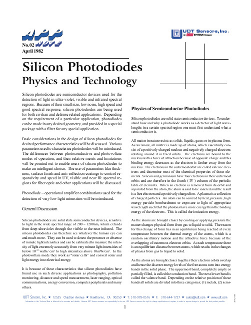
oPTical ProPerTies of selecTeD eleMenTs J. h. Weaver and h. P. r. frederikseThese tables list the index of refraction n, the extinction coeffi-cient k, and the normal incidence reflection R (φ = 0) as a function of photon energy E, which is expressed in electron volts (eV) . To convert the energy in eV to the wavelength in µm, use λ = 1 .2398/E . To compute the dielectric function ˜ε = ε1 + iε2 from the complex index of refraction ˜N = n + ik, use ε1 = n2 – k2 and ε2 = 2nk .The optical constants in these tables are abridged from three more extensive tabulations:•Optical Properties of Metals (OPM), Volumes I and II, Physics Data, Nr . 18-1 and 18-2, J . H . Weaver, C . Krafka, D . W . Lynch, and E . E . Koch, Fachinformationzentrum, Karlsruhe, Germany .•Handbook of Optical Constants (HOC), Vol . I, 1985, and Vol . II, 1991 . E . D . Palik, Ed ., Academic Press, Inc ., London .•American Institute of Physics Handbook (AIPH), 3rd Edition, D . E . Gray, Ed ., McGraw-Hill, New York, 1972 .The first two of these major sources provide detailed compari-sons of all optical data available in the literature at the time of the compilation . For critical applications the reader should refer to the original work . References for individual metals and semiconduc-tors are listed at the end of the tables . Generally, tabulated values for the optical properties are accurate to better than 10% . Data in parentheses are extrapolated or interpolated values . For most elements the spectral range covered is from the far infrared (0 .010 or 0 .10 eV) to the far ultraviolet (10, 30 or 300 eV) . The intervals between successive energies in the tables are chosen in such a way that the major spectral features are preserved .Very small values of k are expressed in exponential notation, e .g ., 1 .23E-5 means 1 .23 × 10-5 .The following table is convenient for associating the energy en-tries in these tables with the corresponding wavelengths:
λE/eVλE/eV1 mm0 .001246000 Å2 .066500 µm0 .002485000 Å2 .480100 µm0 .012404000 Å3 .10050 µm0 .024803000 Å4 .13310 µm0 .123982000 Å6 .1995 µm0 .247971000 Å12 .3981 µm1 .240400 Å30 .996
Energy (eV)nkR(φ = 0)
Aluminum1
0 .04098 .595203 .7010 .99230 .05074 .997172 .1990 .99150 .06062 .852150 .7990 .99060 .07053 .790135 .5000 .98990 .08045 .784123 .7340 .98950 .09039 .651114 .1020 .98920 .10034 .464105 .6000 .98890 .12524 .96589 .2500 .98840 .15018 .57276 .9600 .98820 .17514 .27466 .9300 .98790 .20011 .73359 .3700 .98730 .2508 .58648 .2350 .98580 .3006 .75940 .9600 .98440 .3505 .43835 .5990 .98340 .4004 .45431 .4850 .98260 .5003 .07225 .5810 .98170 .6002 .27321 .4030 .98060 .7001 .77018 .3280 .97940 .8001 .44415 .9550 .97780 .9001 .26414 .0210 .97491 .0001 .21212 .4640 .96971 .1001 .20111 .1810 .96301 .2001 .26010 .0100 .95211 .3001 .4688 .9490 .93181 .4002 .2378 .2120 .88521 .5002 .7458 .3090 .86781 .6002 .6258 .5970 .87941 .7002 .1438 .5730 .89721 .8001 .7418 .2050 .90691 .9001 .4887 .8210 .91162 .0001 .3047 .4790 .9148
Energy (eV)nkR(φ = 0)2 .2001 .0186 .8460 .92002 .4000 .8266 .2830 .92282 .6000 .6955 .8000 .92382 .8000 .5985 .3850 .92423 .0000 .5235 .0240 .92413 .2000 .4604 .7080 .92433 .4000 .4074 .4260 .92453 .6000 .3634 .1740 .92463 .8000 .3263 .9460 .92474 .0000 .2943 .7400 .92484 .2000 .2673 .5520 .92484 .4000 .2443 .3800 .92494 .6000 .2233 .2220 .92494 .8000 .2053 .0760 .92495 .0000 .1902 .9420 .92446 .0000 .1302 .3910 .92576 .5000 .1102 .1730 .92607 .0000 .0951 .9830 .92627 .5000 .0821 .8140 .92658 .0000 .0721 .6630 .92698 .5000 .0631 .5270 .92729 .0000 .0561 .4020 .92779 .5000 .0491 .2860 .928210 .0000 .0441 .1780 .928610 .5000 .0401 .0760 .929311 .0000 .0360 .9790 .929811 .5000 .0330 .8830 .928312 .0000 .0330 .7910 .922412 .5000 .0340 .7000 .911813 .0000 .0380 .6090 .896013 .5000 .0410 .5170 .878914 .0000 .0480 .4170 .848614 .2000 .0530 .3730 .8312Energy (eV)nkR(φ = 0)14 .4000 .0580 .3270 .810214 .6000 .0670 .2730 .780214 .8000 .0860 .2110 .720215 .0000 .1250 .1530 .611915 .2000 .1780 .1080 .490315 .4000 .2340 .1840 .388115 .6000 .2800 .0730 .318215 .8000 .3180 .0650 .269416 .0000 .3510 .0600 .232616 .2000 .3800 .0550 .203116 .4000 .4070 .0500 .178916 .7500 .4480 .0450 .146017 .0000 .4740 .0420 .127817 .2500 .4980 .0400 .112917 .5000 .5200 .0380 .100517 .7500 .5400 .0360 .089918 .0000 .5580 .0350 .080918 .5000 .5910 .0320 .066419 .0000 .6200 .0300 .055419 .5000 .6460 .0280 .046720 .0000 .6680 .0270 .039820 .5000 .6890 .0250 .034221 .0000 .7070 .0240 .029621 .5000 .7240 .0230 .025822 .0000 .7390 .0220 .022622 .5000 .7530 .0210 .019923 .0000 .7660 .0210 .017723 .5000 .7780 .0200 .015724 .0000 .7890 .0190 .014024 .5000 .7990 .0180 .012625 .0000 .8090 .0180 .011325 .5000 .8170 .0170 .010226 .0000 .8260 .0160 .0092