SAR雷达目标信号模拟器案例
临近空间方向-高分辨率对地观测学术年会讲课讲稿

中国空间技术研究院西安分院
5
基于移时正交波形的MIMO-SAR体制研 究
王伟
中国科学院电子学研究所
6
光学遥感运动补偿压缩成像
王泽龙频干扰抑制方法研究
赵腾飞
国防科学技术大学
8
基于光纤阵列耦合的多波束光子计数激 光三维成像雷达航空模拟器的设计与验 证
舒嵘
中国科学院上海技术物理研究 所
9
咼分辨率对地观测中的图像挖掘研究
张守娟
中国空间技术研究院西安分院
10
地球同步轨道对地遥感卫星成像质量仿 真系统
程侃
北京空间飞行器总体设计部
11
高比能量锂离子蓄电池技术研究
黄莉
上海空间电源研究所
12
卫星平台变频动力吸振技术研究
黄俊杰
上海卫星工程研究所
13
光学遥感图像舰船目标识别系统设计
苗慧
中国空间技术研究院513所
单位
1
基于半粘贴式FBG的蒙皮应变监测机理
研究
王全保
上海交通大学
2
F12纤维织物编织疏密对蒙皮焊接带粘 接性能的影响
邓云飞
中国航天科工集团第六研究院
46所
3
移动式临近空间大气密度/温度/风场激
光雷达研究
闫召爱
中国科学院空间科学与应用研 究中心
4
临近空间环流和温度的冬-夏季节转换特 征及影响因素
张玉李
19
一种适用于多通道机载SAR/GMTI的改
进DPCA算法
侯丽丽
中国科学院电子学研究所
20
光轴偏心相机内方位元素测试技术研究
马丽娜
北京空间机电研究所
21
高动态范围红外点源/成像目标模拟器技 术
【国家自然科学基金】_x波段雷达_基金支持热词逐年推荐_【万方软件创新助手】_20140729
推荐指数 2 2 1 1 1 1 1 1 1 1 1 1 1 1 1 1 1 1 1 1 1 1 1 1 1 1 1 1 1 1
2010年 序号 1 2 3 4 5 6 7 8 9 10 11 12 13 14 15 16 17 18 19 20 21 22 23 24 25 26 27 28 29 30 31 32 33 34 35 36 37 38 39 40 41 42 43 44 45 46 47 48
科研热词 推荐指数 海杂波 3 相态识别 2 高速采样 1 非参量检测器 1 降水性层状云 1 降水估测 1 阚值分割 1 逆合成孔径雷达 1 连续波雷达 1 车载x波段双线偏振多普勒天气雷达 1 谱线增强器(ale) 1 线性调频 1 纹理特征 1 瞬时极化测量 1 瞬态极化雷达 1 直接数字频率合成(dds) 1 目标检测 1 现场可编程门阵列(fpga) 1 滞后效应 1 湿地植被 1 淹没区域 1 测量 1 模糊逻辑 1 极化雷达 1 极化散射矩阵 1 极化 1 数据处理系统 1 捷变频 1 恒虚警率 1 微多普勒 1 微动 1 峰度 1 射线状噪声 1 外场实验 1 图像欺骗干扰 1 后向散射系数 1 合成孔径雷达 1 可变步长lms 1 反距离加权法 1 动目标检测 1 分时极化测量 1 分数阶fourier变换(frft) 1 分形 1 先进合成孔径雷达 1 主成分分析法 1 x波段雷达 1 swerling起伏 1 log算子 1
1 1 1 1 1 1 1 1 1 1 1 1 1 1 1 1 1 1 1 1 1 1 1 1 1 1 1 1 1 1 1 1 1 1 1 1 1 1 1 1 1 1 1 1 1 1
2008年 序号 1 2 3 4 5 6 7 8 9 10 11 12
风电场毫米波雷达技术研究及应用

风电场毫米波雷达技术研究及应用摘要:现阶段,“碳达峰,碳中和”发展战略的执行效果越发显著,再加上电力体制的改革工作持续深入,对我国风电行业的发展具有良好的推动作用。
本文以上述内容为基础,针对风电场毫米波雷达技术展开研究,分析毫米波雷达技术的关键作用,整理相关经验,给出针对性发展建议,希望能够为同领域工作者提供合理参考作用。
关键词:风电场;毫米波雷达技术;新能源开发与应用前言:风能作为重要的可再生清洁能源之一,在现代化电力系统中承载着越来越重要的电力支持任务。
其中,风场信息测量工作作为风电行业保持良好发展状态的重要内容,属于风电场内不可或缺的重要组成结构。
在风力发电机工作并获取风能的过程中,为进一步提升电能的实际生产效率,需借助传感技术,主动感知风速、风向信息,并辅助完成风机控制任务,及时校正偏航误差问题,通过这种方式准确控制风机的最终指向,达到提升发电总量的效果。
一、米波雷达测风基本原理常规情况下,风资源评估、风功率预测系统、风电场运营管理等内容均属于风力发电系统中的重要内容,因此,需要对300m范围内的所有风速风向信息进行全面探测[1]。
在传统类型的风场中,测风塔作为主要测量工具,发挥着重要作用,但是,因其建设成本相对较高,并且灵活度不足,在风场测量工作中存在较多不便,所以,需要找出一种更加便捷且准确的探测技术,完成测风任务。
基于此,以激光和声波技术为主的测风雷达设备在风力发电行业中的应用正变得越发广泛,但是,在实际使用过程中,同样存在一些问题会对探测效果造成影响,需要得到妥善处理。
本文以上述内容为背景,对现有新型测风技术及其产品进行详细说明,即毫米波测风雷达设备,该设备不仅可以在不同高度内准确测得风力信息,同时还可以保证自身在各种不良环境下保持稳定工作状态,保证最终测得数据的准确性。
在此期间,在实际使用的过程中还具有天候、雨天性能好、无噪声、低功耗等诸多使用优势,可以为相关企业和技术人员提供更为优质的辅助效果。
Sar的基础知识
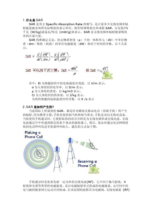
1.什么是SARSAR是英文Specific Absorption Rate的缩写,是计量多少无线电频率辐射能量被身体所实际吸收的表示单位,称作特殊吸收比率或称SAR,以瓦特/每千克 (W/kg)或毫瓦/每克 (mW/g)来表示。
SAR是无线电频率辐射能量吸收率的计量尺度。
SAR的准确定义是:给定物质密度(ρ)下的一体积单元(dV)中单位物质(dm)吸收(耗损)的单位电磁能量(dW)相对于时间的导数,以下式表示:其中:Ei为细胞组织中的电场强度有效值,以V/m表示;σ为人体组织的电导率,以S/m表示;ρ为人体组织密度,以kg/m3表示;Ci为人体组织的热容量,以J/kg表示,为组织细胞的起始温度时间导数,以K /s表示2.SAR是如何产生的?当前国际上所谈到的SAR,都是针对蜂窝式移动电话(俗称手机)所产生的辐射。
因为携带方便,手机发展的相当快和相当普及。
手机是双向无线电设备。
当你使用手机通话时,它便拾取你的语音并转化为无线电频率或无线电波。
无线电波通过空中传递到附近的某个基站的接收器上。
然后,基站再通过电话网络将你的电话呼叫发送至你要呼叫的人。
通信的方式如下图:手机通话时是依靠发射一定功率的无线电波(RF),它不同于伽马射线、X射线和光谱等类型的电磁能量,是以电磁辐射形式组成的电磁能量,由空间中的电与磁的能量相互运动共同组成,在该范围的波称其为电磁场。
无线电辐射 (RF)能量的用途广泛,电信、无线电收音机、电视广播、无线电话、寻呼机、非接触卡电话、警察和消防部门的无线电工具)、点对点联络和卫星通讯均依赖于无线电频率辐射(RF)能量。
另外的用途还包括微波炉、雷达、工业加热器、熨斗、医疗设施等。
微波频率段的无线电(RF)能量能够热水,能够快速烹调含水量大的食品;雷达依赖于无线电 (RF)跟踪汽车和飞机,并用于军事用途;工业炉和熨斗使用无线电 (RF)能量加工成形可塑材料、胶木制品、密封皮革如鞋和皮夹、加工食品;无线电 (RF)能量的医疗用途包括起搏器的监控和操作。
【国家自然科学基金】_雷达测距_基金支持热词逐年推荐_【万方软件创新助手】_20140801

科研热词 距离估计 测距 雷达 障碍检测 运动补偿 越野环境 融合算法 聚类 结构随机跳变系统 空间对准 相位差 激光雷达 激光测距雷达 激光技术 混沌激光 混沌 深度图 海面无线传感器网络 汽车防撞雷达 最佳线性无偏估计 最优滤波 时间同步 无源定位 文字间用 弹栽被动系统 干涉仪 宽带一维距离像 实时测距 多普勒 号隔开空半格 可见光图像 参数估计 单脉冲测角 协同定位 到达时间 光通信 光时域反射仪 交叉干扰 markov跳变参数系统 gdop
2012年 序号 1 2 3 4 5 6 7 8 9 10 11 12 13 14 15 16 17 18 19 20 21 22 23 24 25 26 27 28 29 30 31 32 33 34 35 36 37 38 39 40 41 42 43 44 45 46 47 48 49 50 51 52
推荐指数 2 2 1 1 1 1 1 1 1 1 1 1 1 1 1 1 1 1 1 1 1 1 1 1 1 1 1 1 1 1 1 1 1 1 1 1 1 1 1 1
2010年 序号 1 2 3 4 6 7 8 9 10 11 12 13 14 15 16 17 18 19 20 21 22 23 24 25 26 27 28 29 30 31 32 33 34
2013年 序号 1 2 3 4 5 6 7 8 9 10 11 12 13 14 15 16 17 18 19 20 21 22 23 24 25 26 27 28 29 30 31 32 33 34 35 36 37 38 39 40 41 42 43 44 45 46 47 48
2008年 序号 1 2 3 4 5 6 7 8 9 10 11 12 13
科研热词 采样比率 遗传算法 距离闪烁 聚类 相邻距离单元采样 特征提取 激光雷达 测速 机动目标 广义似然比 宽带信号 分数傅里叶变换 不可分辨目标
【国家自然科学基金】_雷达回波信号_基金支持热词逐年推荐_【万方软件创新助手】_20140801

1 1 1 1 1 1 1 1 1 1 1 1 1 1 1 1 1 1 1 1 1 1 1 1 1 1 1 1 1 1 1 1 1 1 1 1 1 1 1 1 1 1 1 1 1 1 1 1 1 1 1 1 1 1
53 54 55 56 57 58 59 60 61 62 63 64 65 66 67 68 69 70 71 72 73 74 75 76 77 78 79 80 81 82 83 84 85 86 87 88 89 90 91 92 93 94 95 96 97 98 99 100 101 102 103 104 105 106
科研热词 合成孔径雷达 目标识别 目标检测 极化散射矩阵 运动补偿 空域极化特性 特征提取 探地雷达 地面运动目标检测 高分辨距离像 频率步进雷达 通道均衡 距离模糊 超分辨 脉冲压缩 耦合 编码激励 空时自适应处理 相关性 成像 幅相误差 射频干扰 宽测绘带 合成孔径激光雷达 参数估计 前视阵雷达 分布式卫星 insar构型 高频雷达 高斯模式 频谱搜索 频率分集 面向仪器系统的外围部件互连扩展总线 非高斯 非连续谱 非相干散射 非均匀 雷达自动目标识别 雷达目标识别 雷达目标 雷达昆虫学 雷达散射截面 雷达成像 雷达回波 随机等效采样 随机相位编码 降维 锥形尺度变换(tst) 鉴别 重叠因子 遗传算法 速度加速度分辨
2009年 序号 1 2 3 4 5ห้องสมุดไป่ตู้6 7 8 9 10 11 12 13 14 15 16 17 18 19 20 21 22 23 24 25 26 27 28 29 30 31 32 33 34 35 36 37 38 39 40 41 42 43 44 45 46 47 48 49 50 51 52
大气激光雷达 1 大气后向散射系数 1 大气光学 1 大气与海洋光学 1 多目标 1 多普勒谱 1 多普勒波束锐化 1 多径模型 1 多发多收系统 1 外辐射源雷达 1 基线选择 1 地面动目标检测 1 地面动日标检测 1 土壤污染 1 回波抵消 1 合成带宽 1 合成孔径雷达/逆合成孔径雷达 1 合成孔径雷达-运动目标检测 1 双通道对消 1 参考通道 1 参数估计 1 原始数据 1 压制干扰 1 卷云 1 单距离匹配滤波 1 协同空战 1 匹配追踪算法 1 动态规划 1 前视探地雷达 1 前置放大电路 1 切趾滤波 1 分数阶傅立叶变换 1 分数傅里叶变换 1 冰川探测雷达 1 全极化一维距离像 1 光电倍增管(pmt) 1 假像 1 信杂比 1 信噪比 1 信号提取 1 信号处理 1 仿真 1 令牌环网 1 介电常数 1 互信息 1 乘积因子 1 主轐 1 中频采样 1 中气旋 1 wiguer-hough变换 1 radon变换 1 radon-wigner变换 1 radon-ambiguity变换 1 multiple-input,multiple-output(mimo)雷达 1
GSG-5 6 卫星导航信号模拟器产品介绍说明书

Basic PrincipleG SG -5/6 simulators can generate any combination of G PS, G LONASS, G alileo, BeiDou, QZSS, SBAS satellite signals un-der any condition simultaneously through a single RF out-put (type N connector). Configurations with higher channel counts generate new, modernized, signals on any of the navi-gation frequencies, including IRNSS, even those currently un-der development. Based on a test scenario that includes date, time and power levels, the generated signals correspond to any position on, or above, the earth (below the satellite orbits at approximately 20,000 km). It is easy to test dynamic condi-tions by defining a trajectory of the receiver under test. The simulator manages all the dynamics including relativistic effects.Test Solutions•Position/navigation accuracy •Dynamic range/sensitivity•Simulate movements/trajectories anyway on or above earth •Susceptibility to noise•Sensitivity to GPS impairments: loss of satellites, multi-path, atmospheric conditions, interference, jamming and spoofing •Conducted or over-the-air RF •GPS time transfer accuracy •Effect of leap second transition •Multiple constellation testing•Modernization signals/ frequencies •Hardware in the loop integrationGSG-5/6 SeriesAdvanced GNSS Simulators•Pre-defined or user-defined test scenarios•Full control over all test parameters•Front panel interface/stand-alone operation•Windows-based scenario builder software including Google Maps •Remote operation by Ethernet, GPIB, USB •Built-in or downloadable navigation files•Full control over trajectories and other dynamics •Up to 64 simultaneous signals•All GNSS constellations and frequencies•Accurate, adjustable power levels•Synchronization features to external devices or other simulatorsSimulation is simply the best way to test and verify proper operation of devices, systems and software reliant on global navigation satellite signals.Pendulum G SG -5/6 series simulators are easy-to-use, feature-rich and affordable to offer the best value compared to alternative testing tools or the limitations of testing from “live sky” signals. | *****************************•Constellations: GPS, GLONASS, Galileo, BeiDou, QZSS, IRNSS •Modulations: BPSK, QPSK, BOC (all)•SBAS: WAAS, EGNOS, GAGAN, MSAS, SAIF (included)•Spurious transmission: ≤40 dBc •Harmonics: ≤40 dBc•Output signal level: -65 to -160 dBm; 0.1 dB resolution down to -150 dBm; 0.3 dB down to -160 dBm•Power accuracy: ±1.0 dB •Pseudorange accuracy: Within any one frequency band:1 mm; Across different frequency bands: 30 cm•Inter-channel bias: Zero•Inter-channel range: >54 dB •Limits:Standard ExtendedAltitude18,240 m(60,000 feet)20,200,000 m (66,273,000 feet)Acceleration 4.0 g No limitsVelocity515 m/s (1000knots)20,000 m/s (38,874 knots)Jerk20 m/s3No limit •White noise signal level: -50 to -160 dBm; 0.1 dB resolution down to -150 dBm;0.3 dB down to -160 dBm. ±1.0 dB accuracy External Frequency Reference Input •Connector: BNC female•Frequency: 10 MHz nominal•Input signal level: 0.1 to 5Vrms•Input impedance: >1kΩFrequency Reference Output •Connector: BNC female•Frequency: 10 MHz sine•Output signal level: 1Vrms in to 50 Ω load External Trigger Input•Connector: BNC female•Level: TTL level, 1.4V nominalXPPS Output•Connector: BNC female•Rate: 1, 10, 100, 1000 PPS (configurable)•Pulse ratio: 1/10 (1 high, 9 low)•Output signal level: approx. 0V to +2.0V in 50 Ω load•Accuracy: Calibrated to ±10 nSec of RF timing mark output (option to reduce by a factor of ten with a characterization of offsets)Built-in TimebaseInternal Timebase – High Stability OCXO •Ageing per 24 h: <5x10⁻¹⁰•Ageing per year: <5x10⁻⁸•Temp. variation 0…50°C: <5x10⁻⁹•Short term stability (Adev @1s): <5x10-12 Auxiliary FunctionsInterface•GPIB (IEEE-488.2), USB 1.X or 2.X (SBTMC-488), Ethernet (100/10 Mbps)Settings•Predefined scenarios: User can change date, time, position, trajectory, number of satellites, satellite power level and atmospheric model •User defined scenarios: Unlimited •Trajectory data: NMEA format (GGA or RMC messages, or both), convert from other formats with GSG StudioView™ (see separate datasheet)General SpecificationsCertifications•Safety: Designed and tested for Measurement Category I, Pollution Degree 2, in accordance with EN/IEC 61010-1:2001 and CAN/CSA-C22.2 No. 61010-1-04 (incl. approval)•EMC: EN 61326-1:2006, increased test levels per EN 61000-6-3:2001 and EN 61000-6-2:2005 Dimensions•WxHxD: 210 x 90 x 395 mm(8.25” x 3.6” x 15.6”)•Weight: approx. 2.7 kg (approx. 5.8 lb) Optional Antenna•Frequency: 1000 to 2600 MHz •Impedance: 50 Ω•VSWR: <2:1 (typ)•Connector: SMA male•Dimensions: 15 mm diameter x 36 mm length Environmental•Class: MIL-PRF-28800F, Class 3•T emperature: 0°C to +50°C (operating); -40°C to +70°C non-condensing @ <12,000 m (storage)Humidity:•5-95 % @ 10 to 30°C•5-75 % @ 30 to 40°C•5-45 % @ 40 to 50°CPower•Line Voltage: 100-240 V AC, 50/60/400 Hz •Power Consumption: 40 W max.Simple Set-up and Operation Even the most inexperienced operator can configure scenarios on-the-fly without the need for an external PC and pre-compila-tion phase. Via the front panel, the user can swiftly modify parameters. Each unit comes with a license for GSG StudioView™ Windows software to graphically create, modify, and upload scenarios. A G oogle Maps interface makes trajectory creation easy. Trajectories can also be defined by recorded or generated NMEA formats. Connectivity Extends Ease-of-use and FlexibilityG SG simulators can be controlled via an Ethernet network connection, USB or GPIB. A built-in web interface allows complete operation of the instrument through front panel controls. It also al-lows for file transfers. Connectivity also supports the integration of G NSS simula-tion into a wide range of other applica-tions. There is an option to control signal generation in real-time through a simple command set. It can synchronize to ex-ternal systems in many other ways based on its precision timing capabilities and the ability to automatically download ephem-eris and almanac data via RINEX files. Input/OutputRF GNSS Signal Generation •Connector: Type N female•DC blocking: internal, up to 7 VDC; 470 Ωnominal load•Frequency bands:•L1/E1/B1/SAR: 1539 to 1627 MHz•L2/L2C: 1192 to 1280 MHz•L5/E5/B2: 1148 to 1236 MHz•E6/B3:1224 to 1312 MHz•Output channels:•1 (GSG-51); 4, 8, 16 (GSG-5); 32 (GSG-62),48, (GSG-63), 64 (GSG-64)•Any channel can generate anyconstellation or a derivative signal(multipath, interference, jamming)•Any set of 16 channels can generate withina frequency bandOptional FeaturesRecord and Playback (OPT-RP)This option provides the easiest way to create a complex scenario by recording satellite signals on a route. This option includes a recording receiver and software to automatically generate a simulation scenario that can be modified to ask ‘what if’ questions.•True life constellation replication •Automatic scenario generation•Ability to modify signal parameters •Compatible with any recording that includes NMEA 0183 RMC, GGA, and GSV sentences Real-time Scenario Generator (OPT-RSG) This option supports generation of 6DOF trajectory information via position, velocity, acceleration, or heading commands as the input for GPS RF generation. Vehicle attitude and attitude rate changes, as well as satellite power levels, are also controllable via real-time commands.•Control trajectories using 6DOF•Low fixed latency from command input to RF output•Hardware-in-the-loop applications •Includes sensor simulation optionRTK/DGNSS Virtual Reference Station (OPT-RTK)This option supports generation of RTCM correction data messages for testing an RTK / Differential-GNSS receiver.•Generates RTCM 3.x correction data via 1002, 1004, 1006, 1010, 1012, and 1033 messages•User settable base station location •Support for GNSS RTK receivers using serial interfacesHigh Velocity Option (OPT-HV)This option extends the limits for simulated trajectories. As of August 2014, the extended limits are no longer USA export controlled. (See Limits chart under Input/Output specifications.) Jamming Simulation (OPT-JAM)This option extends the capability of the standard interference simulation feature. Set noise or sweep types of interference and create a location-based jammer to test your system’s susceptibility.•Adjustable bandwidth and amplitude interference•Location-based jamming•Swept-frequency jammingeCall Scenarios (OPT-ECL)This option provides scenarios for testing eCall in vehicle systems per Regulation (EU) 2017/79.Sensor Simulation (OPT-SEN)This option generates sensor data in responseto a query according to the trajectory of theGPS RF simulation in real-time. See technicalnote for more details.•Simultaneously test GPS plus other sensorinputs to your nav system•Simulate data for accelerometers,gravimeters, gyroscopes and odometersOrdering InformationBase Configurations•GSG-51: Single channel GPS L1 generator(contact the factory for alternativeconstellations and upgrades to multi-channeland/or frequencies)•GSG-5: 4-channel GPS L1 simulator.Software options increase output channelsto 8 or 16, and adds GLONASS, BeiDou (B1),Galileo (E1), or QZSS constellations. Factoryupgradable to GSG-62 to add more channeland/or frequencies)•GSG-62: 32-channels and up to 2simultaneous frequency bands. Softwareoptions adds GLONASS, BeiDou, Galileo,QZSS or IRNSS constellations; and addssignals on other frequencies (P-code, L2,L2C, Galileo E5a/b, BeiDou B2)•GSG-63: 48-channels and up to 3simultaneous frequency bands. Samesoftware options as GSG-62•GSG-64: 64-channels and up to 4simultaneous frequency bands. Samesoftware options as GSG-62Included with instrument•User manual and GSG StudioView software(one license per unit) on CD•RF cable, 1.5 m•SMA to Type N adapter•USB cable•Certificate of calibration•3-year warranty1Optional Accessories•Option 01/71: Passive GNSS Antenna•Option 22/90: Rack-mount kit•Option 27H: Heavy-duty hard transport case•OM-54: User Manual (printed)•Additional StudioView licenses are availableOptional UpgradesConstellations•OPT-GLO: GLONASS Constellation•OPT-GAL: Galileo Constellation•OPT-BDS: BeiDou Constellation•OPT-QZ: QZSS Constellation•OPT-IRN: IRNSS Constellation (requires atleast GSG-62 and OPT-L5)Frequencies (requires at least GSG-62; non-GPS signals are enabled when constellationoption is installed)•Option L2: enables GPS L1P, GPS L2P, GLOL2 C/A•Option L2C: enables GPS L2C•Option L5: enables GPS L5, Galileo E5 a/b,BeiDou B2, IRNSS L5•Option L6: enables Galileo E6 b/cChannels/Simultaneous Frequencies2•Option 8: 4-channel to 8-channel upgrade•Option 16: 8-channel to 16-channel upgrade•Option 32/2: 16-channel to 32-channel, dualfrequency upgrade•Option 48/3: 32-channel to 48-channel, threefrequency upgrade•Option 64/4: 48-channel to 64-channel, fourfrequency upgradeApplication Packages (typical requirement for16 channel min)•OPT-RSG: Real-time scenario generator•OPT-HV: High velocity upgrade to extendedlimits•OPT-RP: Record and playback package•OPT-JAM: Jamming package•OPT-RTK: RTK virtual base station scenarios•OPT-SEN: Sensor simulation data via protocol(included with OPT RSG)•OPT-ECL: eCall scenariosOptional Services•Option 90/54:GSG Calibration Service•Option 95/05: Extended warranty to 5 years•GSG-INST: User Training and Installation•OPT-TIM: Timing Calibration Service1Warranty period and available services may vary dependent on country.2Option may require the unit to be returned to factory for upgrade.Models Channels # of Sim.Freq.Upgrade to nexthigher modelUpgradetypeConstellations and Signal T ypes Frequency BandsGSG-5111OPT-4Software GPS L1 C/A IncludedOthers if constellation is ordered:•GLONASS L1 C/A •QZSS L1•Galileo E1•BeiDou B11539-1627 MHz (L1)GSG-541OPT-8Software 8OPT-16Software 16OPT-32/2FactoryGSG-62322OPT-48/3Factory Same as aboveOptions if constellation andfrequency are ordered:•GPS L1P, L2P, GLONASS L2 C/A (OPT L2)•GPS L2C (OPT L2C)•GPS L5, IRNSS L5, Galileo E5a/b,BeiDou B2 (OPT L5)Same as above and 3 other ranges•1192-1280 MHz (L2)•1148-1236 MHz (L5)•1224-1312 MHz (E6/B3)GSG-63483OPT 64/4FactoryGSG-64644––Configuration SummaryOct 29, 2018 rev.2© 2018, Pendulum Instruments and OroliaSpecifications subject to change or improvement without notice.。
【国家自然科学基金】_多普勒频率_基金支持热词逐年推荐_【万方软件创新助手】_20140731

科研热词 合成孔径雷达 多普勒频率 双基地 距离-多普勒 超声电机 脉冲压缩 耦合 级数反演 空时自适应处理 电离层 激光稳频 无源定位 成像 微多普勒 多普勒效应 合成孔径激光雷达 双基机载雷达 信道估计 gps 频率转移函数 频率调制光谱术 频率误差修正 频率管理系统 非线性光学 非线性 非均匀 非参数平滑 雷达数据处理 雷达成像 选择译码转发 逆合成孔径雷达(isar) 逆合成孔径雷达 软件无线电 转角估计 距离依赖性 距离依赖 超声 谱补偿 谱分析 误码率 误差分析 螺旋波 舰船目标 自适应差分相干检测 自聚焦 脉间相位编码 脉冲重复频率 肾积水 统计特性 线性调频步进信号 线性调频信号 算法复杂度
参数估计 卫星定位系统 动物模型 动力学优化设计 劈刀 分段相关 分段匹配滤波 分数阶傅里叶变换 减阻 冷原子 内插滤波 六波混频 全相参 光学粘团 光学晶格 光学外差测量 偏头痛 俯视 俯仰振动 信道时间相关性 信道估计 信杂比 信号模拟器 侧视 伪码调相 传播模式 主旁瓣比 临界频率 上皮细胞 ukf tid pc6脉动 ofdm m序列 mimo系统 mimo信道模型 isar成像 gps g-特征函数 frft-ofdm fpga ers-2 bcl-2
107 108 109 110 111 112 113 114 115 116 117 118 119 120 121 122 123 124 125 126 127 128 129 130 131 132 133 134 135 136 137 138 139 140 141 142 143 144 145 146 147 148 149
2008年 序号 1 2 3 4 5 6 7 8 9 10 11 12 13 14 15 16 17 18 19 20 21 22 23 24 25 26 27 28 29 30 31 32 33 34 35 36 37 38 39 40 41 42 43 44 45 46 47 48 49 50 51 52
- 1、下载文档前请自行甄别文档内容的完整性,平台不提供额外的编辑、内容补充、找答案等附加服务。
- 2、"仅部分预览"的文档,不可在线预览部分如存在完整性等问题,可反馈申请退款(可完整预览的文档不适用该条件!)。
- 3、如文档侵犯您的权益,请联系客服反馈,我们会尽快为您处理(人工客服工作时间:9:00-18:30)。
SAR雷达目标信号模拟器案例
来源:北京华力创通科技股份有限公司作者:发表时间:2010-04-08 16:08:50 目前机载 SAR 雷达设备的主要测试手段是在地面采用点目标信号进行部分指标和分辨率测试。
进
一步完整的成像测试需要安装在运载飞机上进行实际飞行测试,得到最后的指标。
星载 SAR 雷达设备的主要测试手段同样是在地面点目标信号进行部分指标和分辨率测试。
通过
这种测试来估计实际的成像指标。
XXX 型 SAR 雷达目标信号模拟器可以实时模拟回放多点目标和场景目标回波。
用于机载或星载
SAR 雷达设备在地面进行完整的功能和性能指标调试和测试。
XXX 型 SAR 雷达目标回波信号模拟器基本原理是一种数字储频体制的测试信号模拟设备。
接收
来自雷达系统 TR 组件送出的脉冲发射信号,并在此基础上生成触发脉冲和回波信号;实时模拟点目
标回波信号:--能进行时间延迟、能叠加多普勒频移,能进行幅度调制;非实时模拟面目标回波信
号--可叠加地表信息、轨道特性、平台姿态特性和幅相误差、波位特性、天线性能等工程误差
XXX 型 SAR 雷达目标回波信号模拟器主要由三个功能单元组成:
射频单元
将来自雷达系统脉冲发射信号转换到中频,并将中频单元的模拟回波信号混频至射频,通过射频
电缆注入或通过天线回放给被测雷达;
数字中频单元
基于数字储频体制获取中频信号,经过数字变换成多点目标回波中频信号回放给射频单元。
或根
据被测雷达的信号特征,将已经存储的大型场景目标回波回放出去
数学仿真单元
运行 SAR 雷达场景目标模拟生成算法,生成场景(即面目标)回波数据,注入给数字中频单元
技术优势
幅相控制技术
高速 AD/DA 技术( 20M - 1.5G 采样率)
实时点目标运算,非实时面目标模拟
高速板间数据传输技术(单通道最高速率可达 6Gbps )
大容量板级数据存储技术( 20G )
应用方案
雷达系统回波模拟
精密延迟信号实现
用于宽带雷达模拟器
实时记录 SAR 发射信号
实时回放数字信号、模拟各种条件
下的回波信号
技术性能
AD/DA 指标: 1.5GSPS , 10bits
板间数据传输速度: 6 × 6Gbps
单板数据存储容量: 16GB
磁盘阵列容量: 2TB
相位精度:二次相位误差:≤ 10 °
三次相位误差:≤ 8 °
带内幅度波动:± 0.5dB
采样率: 1.2GSPS
多普勒带宽: 2000 - 3000Hz
回波宽度: 80 - 250us ,步长 5us
整体时延:τ +2us - 300us ,步长 0.5us 可调,τ为脉宽。