dsp教程
南京研旭DSP开发板综合调试软件使用教程

研旭D S P 开发板综合调试软件指导手册V 1.1南京研旭电气科技有限公司w ww .n jy xd q.co m南京研旭电气科技有限公司Copyright 2009©yanxu.All rights recerved声明南京研旭电气科技有限公司保留随时对其产品进行修改、改进和完善的权利,同时也保留在不作任何通告的情况下,终止其任何一款产品的供应和服务的权利。
用户在下订单前应获取相关信息的最新版本,并验证这些信息是当前的和完整的。
版权©2009,南京研旭电气科技有限公司w ww .n jy xd q.co m南京研旭电气科技有限公司Copyright 2009©yanxu .All rights recerved一、研旭DS P开发板综合测试软件使用说明为了广大新手在首次接触到研旭DS P 开发板能够方便简单快捷的熟悉和判断开发板的好坏,研旭公司开发出研旭D S P 开发板综合调试平台,方便大家的首次测试和熟悉D S P 开发板。
研旭D S P 开发板综合调试平台分为两部分,第一部分是基于w i n d o w s 平台的上位机软件,第二部分是D S P 开发板上的下位机软件(在出厂时已经将程序烧到开发板当中),综合调试平台可以实现开发板各个功能模块的调试。
二、研旭DS P开发板综合测试软件调试步骤第一步:用交叉串口线连接P C机到开发板上。
第二步:将开发板连接到电源适配器。
第三步:双击研旭D S P 开发板综合调试软件打开,就可以依次进行测试了。
经过上面的三步,我们可以看到研旭D S P 开发板综合测试平台的主界面:w ww .n jy xd q.co m南京研旭电气科技有限公司Copyright 2009©yanxu.All rights recerved这个界面有6个按钮,分别为L E D测试、R T C时钟测试、E E P R O M 测试、外部中断测试、T i me r 0定时器测试以及串口工具。
DSP课件第4章-数字信号处理教程(第2版)-姚天任-清华大学出版社

例4-2 求格型参数,已知 Hz 2 6z1 4z2
1.初始化
H z b0 A2 z 2 1 3z1 2z2 D2 z z2 A2 z1 z2 3z1 2
调用MATLAB函数验证 b=[1 3 -2]; k=tf2latc(b); 结果:k=[-3 -2] b=latc2tf(k); 结果: b=[1 3 -2]
4.3 线性相位FIR滤波器
4.3.1 FIR滤波器的相位响应 4.3.2 线性相位FIR滤波器的冲激响应 4.3.3 线性相位FIR滤波器的结构 4.3.4 线性相位FIR滤波器的振幅响应 4.3.5 线性相位FIR滤波器的零点分布
2. 滤波器无相位失真的条件
相延时是频率的函数。 若输入信号不同频率分量通过滤波器的相延时不
FIR滤波器的级联结构信号流图
4.2 FIR滤波器的格型结构
uvii
n n
ui1n iui1n
ivi1 n vi1n
1 1
u0
n
v0 n b0 yn uN n
xn
1i N
FIR滤波器格型结构的推导
i
前向预测 xˆn ak xn k
k 1
前向预测误差
i
ui n xn xˆn ak xn i
2
lim
z
D2
z
lim
z
z 2
3z 1
2
2
2. 迭代 i 2, 1
A1z
1
1
2 2
A2
z
2 B2
【安富莱】DSP教程-第12章StatisticsMathFunctions的使用(二)

安富莱S T M32-V5开发板数字信号处理教程文档版本:V1.0安富莱电子W W W.A R M F L Y.C O M声明本文档的版权归武汉安富莱电子有限公司所有。
任何公司或者个人未经许可,不得将本文档用于商业目的。
⏹本文档由安富莱电子原创,非我们原创的资料已经在章节的开头进行申明(特别是F F T部分)。
⏹教程中使用的D S P库是来自A R M公司。
⏹教程参考资料如下:◆C o r t e x-M4权威指南。
◆数字信号处理理论、算法与实现第二版(作者:胡广书)。
◆信号与系统第二版(作者:奥本海姆)。
◆M a t l a b的h e l p文档。
◆力科示波器基础应用系列文档。
◆百度百科,w i k i百科。
◆网络资源。
◆S T官方相关文档。
第12章StatisticsMathFunctions的使用(二)本期教程主要讲解统计函数中的标准偏差、均方根和方差的计算。
12.1 标准偏差 Standard deviation12.2 均方差RMS12.3 方差 Variance12.4总结12.1标准偏差S t a n d a r d d e v i a t i o n这部分函数用于计算标准偏差,公式描述如下:Result = sqrt((sumOfSquares - sum2 / blockSize) / (blockSize - 1))其中:sumOfSquares = pSrc[0] * pSrc[0] + pSrc[1] * pSrc[1] + ... + pSrc[blockSize-1] *pSrc[blockSize-1]sum = pSrc[0] + pSrc[1] + pSrc[2] + ... + pSrc[blockSize-1]12.1.1a r m_s t d_f32此函数的使用比较简单,函数定义如下:void arm_std_f32(float32_t * pSrc, uint32_t blockSize, float32_t * pResult)参数定义:[in] *pSrc points to the input vector[in] blockSize length of the input vector[out] *pResult standard deviation value returned here12.1.2a r m_s t d_q31此函数的使用比较简单,函数定义如下:void arm_std_q31(q31_t * pSrc, uint32_t blockSize, q31_t * pResult)参数定义:[in] *pSrc points to the input vector[in] blockSize length of the input vector[out] *pResult standard deviation value returned here注意事项:输入参数是1.31格式的,相乘后输出就是1.31*1.31 = 2.62格式,这种情况下,函数内部使用的64位累加器很容易溢出,并且这个函数不支持饱和运算,这个函数的使用还有一些问题,有待后面解决。
DSP入门培训PPT资料18页
三、DSP中C表达式与基本语句
1、if语句 (1)整型变量与零值比较
应当将整型变量用“==”或“!=”直接与0比较。假设整型变量的名字为value, 它与零值比较的标准if 语句如下:
if (value == 0) if (value != 0) 不可模仿布尔变量的风格而写成 if (value) // 会让人误解value是布尔变量 if (!value)
三、DSP中C语言的关键字
意义 声明自动变量,缺省时编译器一般默认为auto 声明整型变量 声明双精度变量 声明长整型变量 声明字符型变量 声明浮点型变量 声明短整型变量 声明有符号类型变量 声明无符号类型变量 声明结构体变量 声明联合数据类型 声明枚举类型 声明静态变量 用于开关语句 开关语句分支 开关语句中的“其他”分支 跳出当前循环 声明寄存器变量 用以给数据类型取别名(当然还有其他作用)
优秀PPT下载:1ppt/xiazai/ PPT教程: 1ppt/powerpoint/
{ Word教程: 1ppt/word/
资料下载:1ppt/ziliao/ PPT课件下载:1ppt/kejian/
Excel教程:1ppt/excel/
范文下载:1ppt/fanwen/
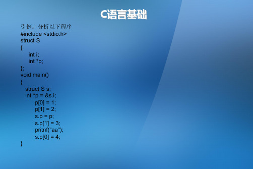
int i;
int *p;
if ((x>=-EPSINON) && (x<=EPSINON)) 其中EPSINON是允许的误差(即精度)。
三、表达式与基本语句
2、循环语句的效率 C++/C循环语句中,for语句使用频率最高,while语句其次,do语句很少用。
提高循环体效率的基本办法是降低循环体的复杂性。
例子: for (row=0; row<100; row++) {
DSP28335教程14 共14页

Single 5V power supply required (not included)
Available through TI authorized distributors and on the TI web
Part Numbers:
TMDSCNCD2808 TMDSCNCD28044 TMDSCNCD28335
F2808 controlCARD On-board digital multi-meter
and active load for transient response tuning C2000 Applications Software CD with example code and full hardware details Digital Power Supply Workshop teaching material and lab software Code Composer Studio v3.3 with code size limit of 32KB 9V DC power supply
Development Support
Module 13 TMS320C28x™ MCU Workshop
T TO
Technical Training Organization
Copyright © 2009 Texas Instruments. All rights reserved.
Learning Objectives
tiworkshop/survey/downloadsort.asp
Login Name: c28xmdw Password: ttoc28
C28x Signal Processing Libraries
【STM32H7的DSP教程】第31章STM32H7实数浮点FFT(支持单精度和双精度)
【STM32H7的DSP教程】第31章STM32H7实数浮点FFT(⽀持单精度和双精度)第31章 STM32H7实数浮点FFT(⽀持单精度和双精度)本章主要讲解实数浮点FTT,⽀持单精度和双精度。
31.1 初学者重要提⽰31.2 实数浮点FFT 说明31.3 单精度函数arm_rfft_fast_f32的使⽤(含幅频和相频)31.4 双精度函数arm_rfft_fast_f64的使⽤(含幅频和相频)31.5 实验例程说明(MDK)31.6 实验例程说明(IAR)31.7 总结31.1 初学者重要提⽰1. 与上⼀章节的复数FFT相⽐,实数FFT仅需⽤户输⼊实部即可。
输出结果根据FFT的对称性,也仅输出⼀半的频谱。
31.2 实数浮点FFT说明CMSIS DSP库⾥⾯包含⼀个专门⽤于计算实数序列的FFT库,很多情况下,⽤户只需要计算实数序列即可。
计算同样点数FFT的实数序列要⽐计算同样点数的虚数序列有速度上的优势。
快速的rfft算法是基于混合基cfft算法实现的。
⼀个N点的实数序列FFT正变换采⽤下⾯的步骤实现:由上⾯的框图可以看出,实数序列的FFT是先计算N/2个实数的CFFT,然后再重塑数据进⾏处理从⽽获得半个FFT频谱即可(利⽤了FFT变换后频谱的对称性)。
⼀个N点的实数序列FFT逆变换采⽤下⾯的步骤实现:实数FFT⽀持浮点,Q31和Q15三种数据类型。
31.3 单精度函数arm_rfft_fast_f32的使⽤(含幅频和相频)31.3.1 函数说明函数原型:void arm_rfft_fast_f32(const arm_rfft_fast_instance_f32 * S,float32_t * p,float32_t * pOut,uint8_t ifftFlag)函数描述:这个函数⽤于单精度浮点实数FFT。
函数参数:第1个参数是封装好的浮点FFT例化,需要⽤户先调⽤函数arm_rfft_fast_init_f32初始化,然后供此函数arm_rfft_fast_f32调⽤。
DSP入门系列--全程详解串行SPI方式bootloader

图四 AT25F1024 内部结构 表三 AT25F1024 指令格式
当从 A T25F1024 读取一个字节时,首先将/ CS 片选信号置低,然后读指令 (READ) 和要读的地址经由 SI 管脚传入,在指定地址的数据(D7 - D0) 经由 SO 管脚传出。如果只读取一个字节,当数据被送出后,/ CS 片选信号将被拉高。当字 节地址自动增加时,读指令(READ) 将继续,数据应将继续被送出,当到达最高地 址(00FFFF) 时,读指令将停止。当将一个字节写入 A T25F1024 时,要执行两条独
表二 TMS320C55X 系列 DSP 芯片的引导表结构
其中,入口地址是引导结束后,用户程序开始执行的首地址;寄存器设置数 量决定后面有多少个 32 比特是作为寄存器设置值或者作为延时等待;16-bit 延 时标志恒为 0XFFFF,以区别于 16-bit 寄存器的地址;段长、段起始地址和数据 是用户程序中定义的各个段的内容;最后以 32 个 0 作为引导表的结束标志。
EEPROM 的读写
AT25F1024 是 Atmel 公司生产的高性能串行 Flash 。存储容量为 1 Mbit (131 ,072*8bit ) 。分为 4 个扇区, 每个扇区容量为 32kbit 。支持扇区擦除和整 片擦除。它的指令格式如表一。
Page 4
BY 红尘有约
DSP 入门系列—全程详解串行 SPI 方式 Bootloader
Page 7
BY 红尘有约
DSP 入门系列—全程详解串行 SPI 方式 Bootloader
SPIWR_Delay(); GPIO_RSET(IODATA,0x10); /*等待 EEPROM 写入完成,最多延时 10 个 ms*/ for(k = 0; k <0x10000;k++) {} MCBSP_close(hMcbsp); }
LabVIEW DSP模块入门教程说明书

Getting Started with the LabVIEW DSP Module Version 1.0ContentsIntroduction (1)Launching LabVIEW Embedded Edition and Selecting the Target (2)Looking at the Front Panel and Block Diagram (3)Running the VI (5)Where to Go for Support.........................................................................6IntroductionUse this tutorial to learn how to create, build, download, and run a DSP VI on a digital signal processor (DSP).This tutorial assumes you are familiar with basic LabVIEW concepts. Refer to the Getting Started with LabVIEW manual, available by selecting Start»Programs»National Instruments»LabVIEW 7.1 Embedded Edition»LabVIEW Manuals and opening gtstrtlv.pdf , for exercises that teach you basic LabVIEW concepts.This tutorial uses the Heterodyne VI, located in the labview embedded\ examples\EmbeddedDSP directory, and an NI SPEEDY-33 board. This example shows double-sideband modulation, also called signal heterodyning or signal mixing.Note You also can use a Texas Instruments 6711 DSK or a Spectrum Digital 6713 DSK target.™Getting Started with the LabVIEW DSP Module Launching LabVIEW Embedded Edition and Selecting the TargetComplete the following steps to launch LabVIEW Embedded Edition andselect the DSP target.1.Launch LabVIEW Embedded Edition.2.In the LabVIEW dialog box, shown in Figure 1, select SPEEDY33from the Execution Target pull-down menu.Note If you are using another supported target, select that target in the Execution Target pull-down menu instead of SPEEDY33.Figure 1. LabVIEW Dialog Box3.Click the Open button, navigate to labview embedded\examples\EmbeddedDSP , and open Heterodyne.vi.© National Instruments Corporation 3Getting Started with the LabVIEW DSP ModuleLooking at the Front Panel and Block DiagramFigure 2 shows the front panel of the Heterodyne VI. You create userinterfaces for DSP VIs in the same way you create user interfaces inLabVIEW for Windows.The waveform graph on the front panel displays the heterodyned signal.You can use the slider controls on the front panel to modify the carrierfrequency and baseband frequency of the signal.Figure 2. Heterodyne VI Front PanelSelect Window»Show Block Diagram and look at the VIs that theHeterodyne VI uses.Tip Press the <Ctrl-E> keys to switch from the front panel to the block diagram or fromthe block diagram to the front panel.Getting Started with the LabVIEW DSP Module Figure 3 shows the block diagram of the Heterodyne VI. The following VIs are used in the Heterodyne VI:•Simulate Signal Express VI —Generates sine waves. One instancegenerates the carrier frequency, and one instance generates the baseband frequency. The two sine waves are multiplied together, which results in a mixed signal. The product of these two signals is the input to the Default AO Elemental I/O Node.•Spectral Measurements Express VI —Computes the FFT and displays the signal on a waveform graph on the front panel.•Analog Output Elemental I/O Node —Writes data to theDigital-to-Analog (D/A) converter, also known as aCODEC (coder-decoder), on the SPEEDY-33 target. You canconfigure how the VI writes data to the analog output bydouble-clicking the Elemental I/O Node.Figure 3.Heterodyne VI Block DiagramRunning the VIClick the Run button to build, download, and run the DSP VI on theSPEEDY-33 target. When you click the Run button, the LabVIEW DSPModule Status Monitor window, shown in Figure 4, appears and displaysthe progress of the build, download, and execution of the DSP VI on theSPEEDY-33 target.Figure 4. LabVIEW DSP Module Status Monitor WindowWhen the VI is running on the DSP target, the front panel moves to thefront. You can modify the carrier frequency and baseband frequency usingthe slider controls on the front panel. When you change the carrierfrequency or baseband frequency, the DSP VI writes the values to the DSPtarget at run time without modifying any of the other code. The waveformgraph on the front panel shown in Figure 2 displays the frequency responseof the signal. If you plug in speakers or headphones to the analog output onthe SPEEDY-33 board, you also can hear the changes to the carrierfrequency and baseband frequency.Click the Stop button to stop the VI.Refer to the labview embedded\examples\EmbeddedDSP directoryfor additional DSP Module examples.© National Instruments Corporation5Getting Started with the LabVIEW DSP ModuleWhere to Go for SupportThe National Instruments Web site is your complete resource for technicalsupport. At /support you have access to everything fromtroubleshooting and application development self-help resources to emailand phone assistance from NI Application Engineers.National Instruments corporate headquarters is located at11500 North Mopac Expressway, Austin, Texas, 78759-3504.National Instruments also has offices located around the world to helpaddress your support needs. For telephone support in the United States,create your service request at /support and follow the callinginstructions or dial 512 795 8248. For telephone support outside the UnitedStates, contact your local branch office:Australia 1800 300 800, Austria 43 0 662 45 79 90 0,Belgium 32 0 2 757 00 20, Brazil 55 11 3262 3599,Canada 800 433 3488, China 86 21 6555 7838,Czech Republic 420 224 235 774, Denmark 45 45 76 26 00,Finland 385 0 9 725 725 11, France 33 0 1 48 14 24 24,Germany 49 0 89 741 31 30, India 91 80 51190000,Israel 972 0 3 6393737, Italy 39 02 413091, Japan 81 3 5472 2970,Korea 82 02 3451 3400, Lebanon 961 0 1 33 28 28,Malaysia 1800 887710, Mexico 01 800 010 0793,Netherlands 31 0 348 433 466, New Zealand 0800 553 322,Norway 47 0 66 90 76 60, Poland 48 22 3390150,Portugal 351 210 311 210, Russia 7 095 783 68 51,Singapore 1800 226 5886, Slovenia 386 3 425 4200,South Africa 27 0 11 805 8197, Spain 34 91 640 0085,Sweden 46 0 8 587 895 00, Switzerland 41 56 200 51 51,Taiwan 886 02 2377 2222, Thailand 662 992 7519,United Kingdom 44 0 1635 523545National Instruments, NI, , and LabVIEW are trademarks of National Instruments Corporation.Refer to the Terms of Use section on /legal for more information about NationalInstruments trademarks. Other product and company names mentioned herein are trademarks or tradenames of their respective companies. For patents covering National Instruments products, refer to theappropriate location: Help»Patents in your software, the patents.txt file on your CD, or/patents.© 2005 National Instruments Corporation. All rights reserved. 371297A-01Apr05。
- 1、下载文档前请自行甄别文档内容的完整性,平台不提供额外的编辑、内容补充、找答案等附加服务。
- 2、"仅部分预览"的文档,不可在线预览部分如存在完整性等问题,可反馈申请退款(可完整预览的文档不适用该条件!)。
- 3、如文档侵犯您的权益,请联系客服反馈,我们会尽快为您处理(人工客服工作时间:9:00-18:30)。
dsp教程
DSP(数字信号处理)是一种处理数字信号的技术,可以用于
音频、视频、图像等信息的处理和传输。
下面将从概念、应用和学习方法三个方面介绍DSP教程。
首先,DSP是数字信号处理的简称,是通过对数字信号进行
算法处理来改变其特性、提取信息或实现特定的功能。
与模拟信号处理相比,DSP具有精度高、灵活性强、抗干扰能力强
等特点。
DSP的应用非常广泛,主要在通信、音频、视频、图像处理
等领域。
在通信领域,DSP可以用于信号的编码、解码、调制、解调等处理;在音频领域,DSP可以用于音频信号的降噪、均衡、音频效果的添加等处理;在视频领域,DSP可以
用于视频信号的压缩、去噪、图像增强等处理。
对于学习DSP的方法,可以参考以下几点。
首先,需要具备
一定的信号与系统的基础知识,包括时域分析、频域分析、傅里叶变换等内容。
其次,可以选择一本优秀的DSP教材进行
学习,例如《数字信号处理(第四版)》、《DSP原理与应用》等。
这些经典的教材中包含了丰富的理论知识、实例分析和实验设计,有助于加深对DSP的理解。
此外,还可以参考在线教程、培训课程和视频教程。
目前,互联网上有很多免费或付费的DSP教程,可以根据自身需要选
择合适的学习资源。
特别是视频教程,通过动态的演示和实践,更能帮助学习者直观地理解DSP的原理和应用。
此外,实践也是学习DSP的重要环节。
可以使用常见的DSP 开发平台,如MATLAB、Python等进行算法的实现和仿真实验。
通过实践,可以加深对DSP理论的理解,并掌握实际应用中的技巧和方法。
总而言之,通过深入学习DSP的理论知识、参考经典教材和在线教程以及进行实践,可以全面掌握DSP的概念、应用和实现方法。
希望这篇简短的DSP教程能够帮助你入门和进一步探索DSP领域。