明纬开关电源LPF-40规格书
断路器安装和使用注意事项说明书

-1-安注意事项:1. 安按产品说明书要求,包括安方式、进线方式、使用条件、铜导线(铜排)截面积(参考值见表11)、使用原厂随机附件等。
2. 额定值是否符合使用要求,包括额定电压、额定电流、额定短路分断能力等等,上下级保护选择要合理。
3. 断路器应清洁,产品上端应无导电物质或其它非导电物质遗落。
4. 断路器安装场所应无爆炸危险、无腐蚀性气体,并应注意防潮、防尘、防震动和避免日晒。
5. 板前接线的断路器可以安装在金属骨架或绝缘板上,板后接线的断路器应安装在绝缘板上。
6. 所有电气联接是否紧固可靠,紧固件联接应根据表14扭矩要求核对。
7. 断路器进行动作特性试验时,应使用经国家有关部门检测合格的专用测试仪器,严禁利用相线直接触碰接地装置的试验方法。
装装装敬告:1. 安装断路器时应按要求,在电弧喷出方向有足够的飞弧距离,并确保相间隔弧板或护罩安装到位,进线端铜排进行了绝缘处理,以防止电弧短路。
2. 安装后应检查断路器与安装板的绝缘电阻。
如有必要对产品进行绝缘测试时,请按以下要求操作:1)用DC 500V兆欧表;2)在断路器处于闭合状态时,对断路器各极分别对地(安装箱金属外壳)间绝缘电阻进行测试;在断路器处于断开状态时,对连接在一起的电源端子与连接在一起的负载端子之间和连接在一起的所有各极带电部件与外壳之间(外壳用金属箔覆盖)分别进行测试;3)绝缘电阻应不小于10M Ω。
3. 因线路短路引起断路器动作后,应更换新的断路器且排除故障后方可投入运行。
4.在使用断路器的情况下,也应保证电气系统接地保护应完好可靠,并且装有剩余电流保护装置。
运行维护:1. 严禁湿手操作断路器,否则可能发生电击事故。
2. 断路器投入运行后,使用单位应作运行记录,并建立相应的管理制度。
3. 断路器因被保护电路发生故障(过载或短路)而分闸时,必须查明原因,排除故障后,才能进行合闸操作。
4. 断路器每六个月进行一次检查,检查时应切断电源,操作手柄使断路器合、分3次,检查机构是否可靠;检查断路器以及断路器与安装板的绝缘电阻,同时清除外壳表面尘-4-注:1. 短路分断能力级别代号:标准型(代号S),较高型(代号H);2. 按操作方式分:手柄直接操作(无代号),电动操作(代号P),转动手柄操作(代号Z);3. 按极数分:三极(代号3),四极(代号4);4. 按用途分:配电保护用(无代号);电机保护用(代号2);5. 四极产品中性极(N)的 型式分为:C型:N极安装过电流脱扣元件,且N极与其它三极一起合分(N极先合 后分);表1 附件名称及代号无附件报警触头分励脱扣器辅助触头欠电压脱扣器分励脱扣器、辅助触头分励脱扣器、欠电压脱扣器二组辅助触头辅助触头、欠电压脱扣器分励脱扣器、报警触头辅助触头、报警触头欠电压脱扣器、报警触头分励脱扣器、辅助触头、报警触头二组辅助触头、报警触头辅助触头、欠电压脱扣器、报警触头300308310320330340350360370318328338348368378附件名称附件代号-5-123456789T 0.3sTR Isd Ii....0.9I R 1.2I RIi (xI n 34681012OFF 2RunOFF0.5 1.0OFFNPTU126080100T (S)9010011012514015016080(A)234568OFF 1.5Isd (xI )2I 4 主要技术参数4.1断路器的额定值见表2。
5V40A超薄LED开关电源5V40A电源LED超薄显示屏超薄电源5V40A电源5V40A开关电源5v40a显示屏电源
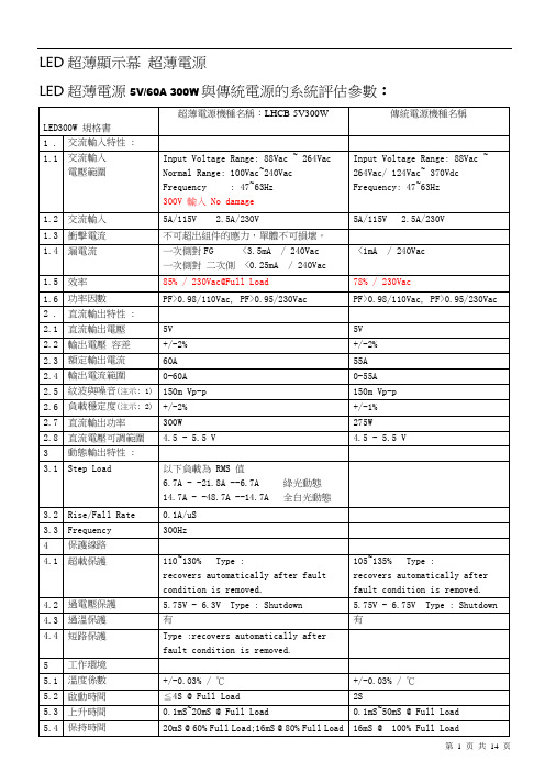
LED超薄顯示幕超薄電源LED超薄電源5V/60A 300W與傳統電源的系統評估參數:LED300W 規格書超薄電源機種名稱:LHCB-5V300W傳統電源機種名稱1 . 交流輸入特性 :1.1 交流輸入電壓範圍Input Voltage Range: 88Vac ~ 264VacNormal Range: 100Vac~240VacFrequency : 47~63Hz300V 輸入 No damageInput Voltage Range: 88Vac ~264Vac/ 124Vac~ 370VdcFrequency: 47~63Hz1.2 交流輸入5A/115V2.5A/230V 5A/115V 2.5A/230V1.3 衝擊電流不可超出組件的應力,單體不可損壞。
1.4 漏電流一次側對FG <3.5mA / 240Vac一次側對二次側 <0.25mA / 240Vac<1mA / 240Vac1.5 效率85% / 230Vac@Full Load 78% / 230Vac1.6 功率因數PF>0.98/110Vac, PF>0.95/230Vac PF>0.98/110Vac, PF>0.95/230Vac2 . 直流輸出特性 :2.1 直流輸出電壓5V 5V2.2 輸出電壓容差+/-2% +/-2%2.3 額定輸出電流60A 55A2.4 輸出電流範圍0-60A 0-55A2.5 紋波與噪音(注示: 1)150m Vp-p 150m Vp-p2.6 負載穩定度(注示: 2)+/-2% +/-1%2.7 直流輸出功率300W 275W2.8 直流電壓可調範圍 4.5 - 5.5 V 4.5 - 5.5 V3 動態輸出特性 :3.1 Step Load 以下負載為 RMS 值6.7A - -21.8A --6.7A 綠光動態14.7A - -48.7A --14.7A 全白光動態3.2 Rise/Fall Rate 0.1A/uS3.3 Frequency 300Hz4 保護線路4.1 超載保護110~130% Type :recovers automatically after faultcondition is removed. 105~135% Type :recovers automatically after fault condition is removed.4.2 過電壓保護5.75V -6.3V Type : Shutdown 5.75V - 6.75V Type : Shutdown 4.3 過溫保護有有4.4 短路保護Type :recovers automatically afterfault condition is removed.5 工作環境5.1 溫度係數+/-0.03% / ℃+/-0.03% / ℃5.2 啟動時間≦4S @ Full Load 2S5.3 上升時間0.1mS~20mS @ Full Load 0.1mS~50mS @ Full Load5.4 保持時間20mS @ 60% Full Load;16mS @ 80% Full Load 16mS @ 100% Full Load5.5 抗震動 10 - 500 Hz ,2G 10min/1 週期 ,30 分鐘 x,y,z 軸10 - 500 Hz ,2G 10min/1 週期 ,30 分鐘 x,y,z 軸5.6 工作溫度1. -40 ℃ ~60 ℃ (參照下圖) :2. -40 ℃ ~50 ℃ @Full Load3. 0 ℃ @ 80%Full Load1. -20 ℃ ~60 ℃ (參照下圖) :2. 0 ℃ ~40 ℃ @Full Load3. 60℃@60%Full Load5.7 散熱方式 PSU 內裝風扇 內裝風扇 5.8 工作濕度 20% ~ 90% RH 20% ~ 90% RH5.9 存儲溫度,存儲濕度 -40 ℃ ~85 ℃ , 10% ~ 90% RH -40 ℃ ~85 ℃ , 10% ~ 95% RH 6安規及EMC 要求6.1 安規標準 IEC60950-1,UL60950-1,CSA C22.2 No.60950-1-03 1, GB4943-2001 TUV EN60950-1,UL60950-1,CCC GB49436.2 EMC 標準諧波電流電磁耐受EN55022 (CISPR22 Class B)EN55024:1998 immunity requirements EN61000-3-2,3IEC61000-4-2,3,4,5,6,8,11 GB9254-2008 GB17625.1-2003EN55022 (CISPR22 Class B) EN61000-3-2,-3EN61000-4-2,3,4,5,6,8,11 ENV50204ENV50204 A 級輕工業標準6.3 耐壓輸入與輸出間 : 3KVac 輸入與外殼 : 1.5KVac 輸出與外殼 : 0.5KVac輸入與輸出間 : 3KVac 輸入與外殼 : 1.5KVac 輸出與外殼 : 0.5KVac6.4 隔離電阻輸入與輸出間 : 500Vdc / 100 MOhms 輸入與外殼 : 500Vdc / 100 MOhms 輸出與外殼 : 500Vdc / 100 MOhms 輸入與輸出間:500Vdc / 100 MOhms 輸入與外殼 : 500Vdc / 100 MOhms 輸出與外殼 : 500Vdc / 100 MOhms 7 機構要求7.1 外形尺寸 220mm x 120mm x 30mm (長*寬*高) 215mm x 115mm x 50mm (長*寬*高) 7.2 重量包裝 0.88Kg ,30PCS/26.4Kg 0.8Kg ,20PCS/16Kg/ 7.3 質保壽命1年1年注示:1.紋波測試:20MHz 用 A12 雙絞線,終端用鉭電容 10μF,並聯一個陶瓷電容0.1μF2.容差 :包括設定容差線路穩定度, 負載穩定度 .注示:1.紋波測試:20MHz 用 A12雙絞線終端並聯47μF 和0.1μF0℃50℃60℃ 300W240W P--T Curve-40℃ 80%100%70℃50%05060300WP--T Curve-20100%5580%50%應用LED超薄顯示幕電源的優勢本文主要從LED顯示幕超薄電源應用于現代顯示幕超薄化的發展趨勢,從超薄電源和超薄箱體的高性價比和廣泛適用性等特點, 加速LED顯示幕領域應用市場的發展,推動LED顯示幕超薄化應用的進程,揭示LED超薄顯示幕電源的應用優勢一、概述LED顯示幕是一種新型的戶內、戶外大尺寸的電子傳播媒體,它具有大尺寸、環境適應性好、亮度高、動態播放等特點,在戶內外大尺寸電子傳播媒體領域獨樹一幟。
台湾明纬开关电源TP-7503-SPEC-CN

SPECIFICATIONTP-75A TP-75B TP-75C MODELDC VOLTAGE RATED CURRENT CURRENT RANGE RATED POWEROUTPUTVOLTAGE ADJ. RANGE LINE REGULATION LOAD REGULATION SETUP, RISE TIME HOLD TIME (Typ.)VOLTAGE RANGE Note.5FREQUENCY RANGE POWER FACTOR (Typ.)EFFICIENCY (Typ.)INPUTINRUSH CURRENT (Typ.)LEAKAGE CURRENT SAFETY STANDARDS HARMONIC CURRENT EMS IMMUNITYWORKING TEMP.WORKING HUMIDITYSTORAGE TEMP., HUMIDITYTEMP. COEFFICIENTVIBRATIONMTBF DIMENSION OTHERSNOTEPACKINGOVER LOADOVER VOLTAGE AC CURRENT (Typ.)5V CH112V CH2-5V CH35V CH112V CH2-12V CH35V CH115V CH2-15V CH37A 3A 0.6A 7A 3A 0.4A 6A 2.5A 0.5A 1.5 ~ 10A 0.2 ~ 4A0 ~ 0.6A1.5 ~ 10A 0.2 ~ 4A0 ~ 0.6A1.5 ~ 10A 0.2 ~ 3A0 ~ 0.6A74W75.8W 75W 100mVp-p120mVp-p 100mVp-p 100mVp-p 120mVp-p 120mVp-p 100mVp-p 120mVp-p 120mVp-p 3.0% 3.0% 3.0%3.0%3.0%3.0%CH1: 4.75 ~ 5.5V 4.0% 4.0% 4.0%4.0%4.0%4.0%8.0%8.0%8.0%8.0%8.0%8.0%1.0% 1.0% 1.0%1.0% 1.0% 1.0%1.0% 1.0% 1.0%800ms, 60ms at full load 36ms at full load90 ~ 264VAC 127 ~ 370VDC47 ~ 63HzPF>0.95/230VAC PF>0.98/115VAC at full load 70%1.5A/115VAC 0.8A/115VAC COLD START 20A/230VAC <2mA / 240VAC105 ~ 150%rated output power5.75 ~6.75V on +5VProtection type : Hiccup mode, recovers automatically after fault condition is removed Protection type : Shut down o/p voltage, re-power on to recover UL60950-1,TUV EN60950-1ApprovedCompliance to EN55022 (CISPR22) Class B Compliance to EN61000-3-2,-3Compliance to EN61000-4-2,3,4,5,6,8,11; ENV50204, EN55024, Light industry level, criteria A -10 ~ +60(Refer to output load derating curve)20 ~ 90% RH non-condensing -20 ~ +85, 10 ~ 95% RH 0.03%/(0 ~ 5010 ~ 500Hz, 2G 10min./1cycle, 60min. each along X,Y, Z axes 198.4K hrs min. MIL-HDBK-217F (25)179*99*33mm (L*W*H)0.65Kg; 20pcs/12.7Kg/0.64CUFTUniversal AC input / Full rangeBuilt-in active PFC function, PF>0.95Protections:Short circuit/Over load/Over voltage Low profile:33mm thickness LED indicator for power on Cooling by free air convectionFixed switching frequency at PFC:67KHz PWM:134KHz 3 years warrantyFeatures :RIPPLE & NOISE (max.)Note.2VOLTAGE TOLERANCE Note.3WITHSTAND VOLTAGEISOLATION RESISTANCE I/P-O/P:3KVAC I/P-FG:1.5KVAC O/P-FG:0.5KVAC 1min.I/P-O/P, I/P-FG, O/P-FG:100M Ohms/500VDCENVIRONMENT SAFETY &EMC(Note 4)PROTECTIONEMI CONDUCTION & RADIATION 1. All parameters NOT specially mentioned are measured at 230VAC input, rated load and 25of ambient temperature.2. Ripple & noise are measured at 20MHz of bandwidth by using a 12" twisted pair-wire terminated with a 0.1uf & 47uf parallel capacitor.3. Tolerance : includes set up tolerance, line regulation and load regulation.4. The power supply is considered a component which will be installed into a final equipment. The final equipment must be re-confirmed that it still meets EMC directives.5. Derating may be needed under low input voltages. Please check the derating curve for more details.OUTPUT NUMBERSPECIFICATIONTP-75D TP-7503MODELDC VOLTAGE RATED CURRENT CURRENT RANGE RATED POWEROUTPUTVOLTAGE ADJ. RANGE LINE REGULATION LOAD REGULATION SETUP, RISE TIME HOLD TIME (Typ.)VOLTAGE RANGE Note.5FREQUENCY RANGE POWER FACTOREFFICIENCY (Typ.)INPUTINRUSH CURRENT (max.)LEAKAGE CURRENT SAFETY STANDARDS HARMONIC CURRENT EMS IMMUNITY WORKING TEMP.WORKING HUMIDITYSTORAGE TEMP., HUMIDITYTEMP. COEFFICIENT VIBRATIONMTBFDIMENSION OTHERSNOTEPACKINGOVER LOADOVER VOLTAGE AC CURRENT5V CH1CH124V CH2CH212V CH3CH35V 3.3V 12V 7A 1.5A 0.4A 9A 8A 0.3A 1.5 ~ 10A 0.2 ~ 2.5A0 ~ 0.6A1.5 ~ 10A 0.2 ~ 8A0 ~ 0.6A75.8W75W 100mVp-p120mVp-p 120mVp-p 100mVp-p 50mVp-p 120mVp-p 3.0% 3.0%3.0% 3.0%CH1: 4.75 ~ 5.5V 4.0% 4.0%4.0%4.0%8.0%8.0%8.0%8.0%1.0% 1.0%1.0% 1.0%1.0% 1.0%800ms, 60ms at full load36ms at full load90 ~ 264VAC 127 ~ 370VDC47 ~ 63HzPF>0.95/230VAC PF>0.98/115VAC at full load 70%1.5A/115VAC 0.8A/115VAC COLD START 20A/230VAC <2mA / 240VAC105 ~ 150%rated output power5.75 ~6.75V on +5VProtection type : Hiccup mode, recovers automatically after fault condition is removed Protection type : Shut down o/p voltage, re-power on to recover UL60950-1,TUV EN60950-1ApprovedCompliance to EN55022 (CISPR22) Class B Compliance to EN61000-3-2,-3Compliance to EN61000-4-2,3,4,5,6,8,11; ENV50204, EN55024, Light industry level, criteria A -10 ~ +60(Refer to output load derating curve)20 ~ 90% RH non-condensing -20 ~ +85, 10 ~ 95% RH0.03%/(0 ~ 5010 ~ 500Hz, 2G 10min./1cycle, 60min. each along X,Y, Z axes 198.4K hrs min. MIL-HDBK-217F (25)179*99*33mm (L*W*H)Universal AC input / Full rangeBuilt-in active PFC function, PF>0.95Protections:Short circuit/Over load/Over voltage Low profile:33mm thickness LED indicator for power on Cooling by free air convectionFixed switching frequency at PFC:67KHz PWM:134KHz 3 years warrantyFeatures :RIPPLE & NOISE (max.)Note.2VOLTAGE TOLERANCE Note.3WITHSTAND VOLTAGE ISOLATION RESISTANCE I/P-O/P:3KVAC I/P-FG:1.5KVAC O/P-FG:0.5KVAC 1min.I/P-O/P, I/P-FG, O/P-FG:100M Ohms/500VDCENVIRONMENT SAFETY &EMC(Note 4)PROTECTIONEMI CONDUCTION & RADIATION 1. All parameters NOT specially mentioned are measured at 230VAC input, rated load and 25of ambient temperature.2. Ripple & noise are measured at 20MHz of bandwidth by using a 12" twisted pair-wire terminated with a 0.1uf & 47uf parallel capacitor.3. Tolerance : includes set up tolerance, line regulation and load regulation.4. The power supply is considered a component which will be installed into a final equipment. The final equipment must be re-confirmed that it still meets EMC directives.5. Derating may be needed under low input voltages. Please check the derating curve for more details.0.65Kg; 20pcs/12.7Kg/0.64CUFTOUTPUT NUMBERMechanical SpecificationDerating CurveOutput Derating VS Input VoltageCase No. 920AUnit:mmAMBIENT TEMPERATURE ()INPUT VOLTAGE (VAC) 60Hz85100115125155230264L O A D (%)L O A D (%)Ta=25Terminal pin number assignment :Pin No.Pin No.14682,357Assignment Assignment DC OUTPUT +V2DC OUTPUT +V1DC OUTPUT +V3COMFG AC/N AC/L1020304050607020406080100-100+ADJ.6.157.6248675231LED253311781794-M4 L=6mm2-M4 L=4mm60659949.532.51718901008070605040With 18CFM Forced AIR(15cm)Convection。
G3VM-401AY DY MOS FET 关联型电源控制元件说明书

1Compact, General-purpose, Analog switching MOS FET Relays, with Dielectric Strength of 5 kVAC between I/O Using Optical Isolation.•Trigger LED forward current of 2 mA (maximum) facilities power saving designs.•Switches minute analog signals.•Continuous load current of 120 mA.■Application Examples■Terminal Arrangement/Internal Connections■List of Models*The AC peak and DC value are given for the load voltage.■Absolute Maximum Ratings (Ta = 25°C)RoHS compliantNote:The actual product is marked differently from theimage shown here.•Electrical power unit•Test & Measurement equipment •Security equipment •Industrial equipmentOMRON logoPin 1 markModel name LOT.NO.Mold pin mark *Note:*The indentation in the corner diagonally opposite from the pin 1 mark is from a pin on the mold.Package type Contact formTerminalsLoad voltage (peak value) *Model Minimum package quantity Number per tube Number per tape and reelDIP41a(SPST-NO)PCB Terminals400 V G3VM-401AY 100-Surface-mounting TerminalsG3VM-401DY G3VM-401DY (TR)-1,500ItemSymbol Rating Unit Measurement conditions I n p u tLED forward current I F 30mA Note: 1. The dielectric strength between the input andoutput was checked by applying voltagebetween all pins as a group on the LED side and all pins as a group on the light-receiving side.Repetitive peak LED forward current I FP 1 A 100 µs pulses, 100 pps LED forward current reduction rate ∆I F /°C −0.3mA/°C Ta ≥ 25°C LED reverse voltage V R 5 V Connection temperature T J 125 °C O u t p u t Load voltage (AC peak/DC)V OFF 400V Continuous load current (AC peak/DC)I O 120mA ON current reduction rate ∆I O /°C −1.2mA/°C Ta ≥ 25°C Pulse ON currentIop 0.36A t = 100 ms, Duty = 1/10Connection temperature T J 125°C Dielectric strength between I/O (See note 1.) V I-O 5000Vrms AC for 1 min Ambient operating temperature Ta −40 to +85°C With no icing or condensation Ambient storage temperature Tstg −55 to +125°C With no icing or condensation Soldering temperature - 260 °C 10 s2G3VM-401AY/DYMOS FET Relays■Recommended Operating ConditionsUse the G3VM under the following conditions so that the Relay will operate properly.■Engineering Data■Safety Precautions•Refer to "Common Precautions" for all G3VM models.ItemSymbol MinimumTypical MaximumUnit Load voltage (AC peak/DC)V DD - - 320V Operating LED forward current I F 3520mAContinuous load current (AC peak/DC)I O - - 120mAAmbient operating temperatureTa−20 - 65 °CLED forward current vs. AmbienttemperatureContinuous load current vs. Ambient temperatureLED forward current vs. LED forward voltageContinuous load current vs. On-state voltageOn-state resistance vs. Ambient temperatureTrigger LED forward current vs. Ambient temperatureTurn ON, Turn OFF time vs. LED forward currentTurn ON, Turn OFF time vs. Ambient temperatureCurrent leakage vs. Ambient temperatureI F - Ta03010204050-40100806040200-20Ambient temperature Ta (°C)L E D f o r w a r d c u r r e n t I F (m A )I O - Ta-20-40100806040200Ambient temperature Ta (°C)015010050C o n t i n u o u s l o a d c u r r e n t I O (m A )0.0110100I F - V FLED forward voltage V F (V)L E D f o r w a r d c u r r e n t I F (m A )I O - V ONOn-state voltage V ON (V)0-160-120-80-408040120160-3-2-10231C o n t i n u o u s l o a d c u r r e n t I O (m A )ON Ambient temperature Ta (°C)01020304050O n -s t a t e r e s i s t a n c e R O N (Ω)012I FT - TaAmbient temperature Ta (°C)T r i g g e r L E D f o r w a r d c u r r e n tI F T (m A )t ON , t OFF - I FLED forward current I F (mA)T u r n O N , T u r n O F F t i m e t ON , t O F F (µs )100010000t ON , t OFF - TaAmbient temperature Ta (°C)101001000T u r n O N , T u r n O F F t i m e t O N , t O F F (µs )I LEAK - TaAmbient temperature Ta (°C)10100C u r r e n t l e a k a g e I L E A K (n A )■Dimensions(Unit:mm)Note:The actual product is marked differently from theimage shown here.PCB Dimensions (BOTTOM VIEW)Actual Mounting Pad Dimensions(Recommended Value, TOP VIEW)Note: The actual product is marked differently from the image shown here.* The indentation in the corner diagonally opposite from the pin 1 mark is from a pin on the mold.+0.1-0.05PCB TerminalsWeight: 0.25 gSurface-mounting TerminalsWeight: 0.25 g• Application examples provided in this document are for reference only. In actual applications, confirm equipment functions and safety before using the product.• Consult your OMRON representative before using the product under conditions which are not described in the manual or applying the product to nuclear control systems, railroad systems, aviation systems, vehicles, combustion systems, medical equipment, amusement machines, safety equipment, and other systems or equipment that may have a serious influence on lives and property if used improperly. Make sure that the ratings and performance characteristics of the product provide a margin of safety for the system or equipment, and be sure to provide the system or equipment with double safety mechanisms.Cat. No. K227-E1-010412(0412)(O)Note: Do not use this document to operate the Unit. OMRON CorporationELECTRONIC AND MECHANICAL COMPONENTS COMPANY Contact: /ecb。
明纬逆变电源样本
明纬逆变电源样本1.型号:MW-1000I技术参数:-输入电压:DC12V-输出电压:AC220V-输出频率:50Hz-额定功率:1000W-不含频率调整范围:±3%-效率:>90%-保护功能:过载保护、短路保护、过温保护-外壳材质:铝合金产品特点:-小巧轻便,易于携带-高效转换,低能耗-高品质的铝合金外壳,有效散热-多种保护功能,保障使用安全-适用于各种电子设备,如电脑、手机、电视等2.型号:MW-2000I技术参数:-输入电压:DC24V-输出电压:AC220V-输出频率:50Hz-额定功率:2000W-不含频率调整范围:±3%-效率:>90%-保护功能:过载保护、短路保护、过温保护-外壳材质:铝合金产品特点:-大功率输出,满足多种设备的需求-高效转换,能源利用率高-显示屏,实时显示输入输出电压和功率-内置风扇,有效降低设备温度-多种保护功能,确保设备和用户的安全3.型号:MW-5000I技术参数:-输入电压:DC48V-输出电压:AC220V-输出频率:50Hz-额定功率:5000W-不含频率调整范围:±3%-效率:>95%-保护功能:过载保护、短路保护、过温保护-外壳材质:铝合金产品特点:-高功率输出,适用于工业环境-高效率转换,节省能源-内置电压稳定器,稳定输出电压-多风扇设计,有效降低设备温度-多种保护功能,保障设备和用户的安全总结:明纬逆变电源样本中,包括MW-1000I、MW-2000I和MW-5000I三款产品。
它们分别具有不同的输入电压和额定功率,可以满足不同用户的需求。
这些逆变电源都具有高效转换、多种保护功能和可靠稳定的输出电压特点,适用于家庭和工业环境中各种电子设备的供电需求。
无论是在户外活动、家庭娱乐还是工业生产中,明纬逆变电源都是一种可靠的选择。
KEMET ALF20 ALF40 金属电容器产品说明书

Printed Circuit Board (PCB) Requirements
PCB Thickness: 1.57 mm Minimum Drill Copper Thickness Final Plated Through-Hole Diameter Pin Insertion Force Pin Retention Force
6.6 1.66 Copper Alloy C7025 Ni and Sn
(Final Plated Through-Hole)
For more information, samples and engineering kits, please visit us at or call 1.877.myKEMET.
SA1017
Copyright © 2017 tible power supply (UPS) • Switch mode power supplies (SMPS) • Smoothing • Energy storage • Demanding power supplies • Frequency inverters
LH40系列40W AC DC 转换器产品说明书
40W,AC/DC converterRoHSFEATURES●Wide input voltage range:85-264VAC/100-370VDC ●Low standby power consumption:0.5W,conversionefficiency up to 84%●Output short circuit,over-current,over-voltage protection●UL60950,EN60950approval●Mounting:PCB mounting,Chassis mounting,DIN-Rail mounting availableLH40series is a 40W efficient environmental-protection AC-DC module power supply,which has advantages such as universal inputvoltage,accept either AC or DC input,high efficiency,high reliability,low power consumption and high safety isolation.The series products are widely used in industries such as industrial control,electricity,office.Note:Please refer to Design Reference when module being used in a bad EMC environment.Selection GuideCertificationPart No.*Output PowerNominal Output Voltage and CurrentEfficiency (230V AC,%/Typ.)Max.CapacitiveLoad(µF)(Vo1/Io1)(Vo2/Io2)UL/CELH40-10B0326.4W3.3VDC/8000mA --7860000LH40-10B0540W 5VDC/8000mA --8240000LH40-10B099VDC/4444mA --8412000LH40-10B1212VDC/3333mA --849000LH40-10B1515VDC/2666mA --847000LH40-10B2424VDC/1667mA --842000LH40-10D0512-135VDC/5000mA 12VDC/1250mA 8210000/470LH40-10D0524-065VDC/5000mA 24VDC/625mA 8210000/400LH40-10A05+5VDC/4000mA -5VDC/4000mA 8212000/12000LH40-10A12+12VDC/1666mA -12VDC/1666mA 844400/4400LH40-10A15+15VDC/1333mA-15VDC/1333mA841000/1000Note:*Product model with a suffix of “A5”means chassis mounting and that with a suffix of “A6”indicates DIN-Rail mounting (e.g.LH40-10B05A5means chassismounting;LH40-10B05A6means DIN-Rail mounting).Input SpecificationsItemOperating Conditions Min.Typ.Max.Unit Input Voltage Range AC input 85--264VAC DC input100--370VDC Input frequency 47--440HzInput current 115V AC ---- 1.0A 230V AC ----0.6Inrush current 115V AC --30--230V AC--50--Hot PlugUnavailableOutput SpecificationsItemOperating Conditions Min.Typ.Max.UnitOutput Voltage AccuracyLH40-10BxxPrimary output--±2--%LH40-10Axx Primary output /Secondary output --±2--LH40-10DxxPrimary output --±2--Secondary output--±5--Line RegulationLH40-10Bxx--±0.5--%LH40-10Axx--±0.5--LH40-10Dxx (Primary output )--±0.5--LH40-10Dxx (Secondary output)--±1.5--Load RegulationLH40-10Bxx--±1--LH40-10Axx (Balance load)--±2--LH40-10Dxx (Balance load)Primary output --±2--Secondary output--±5--Ripple &Noise*20MHz bandwidth (peak-peak value)--50100mV Temperature Coefficient Primary output--±0.02--%/℃Stand-by Power Consumption ----0.5W Short Circuit Protection Continuous,self-recovery Over-current Protection≥110%Io self-recoveryOver-voltage Protection3.3V Output ---- 5.5V5V Output----99V Output ----1412V Output ----1615V Output ----2424V Output ----35Min.LoadLH40-10Bxx0----%LH40-10Axx (Balance load)10----LH40-10Dxx (Balance load)25----Cross RegulationLH40-10A05--±8--LH40-10A12/LH40-10A15--±5--LH40-10DxxPrimary output --±1--Secondary output--±7--TrimLH40-10Bxx ----±10Hold-up Time115V AC input --15--ms 230V AC input--80--Note:*Ripple and noise are measured by “parallel cable”method,please see AC-DC Converter Application Notes for specific operation.General SpecificationsItem Operating Conditions Min.Typ.Max.Unit Isolation VoltageInput-output Test time:1minLH40-10Axx/LH40-10Bxx/LH40-10Dxx 3000----V AC Output-outputLH40-10Dxx500----Operating Temperature -40--+70℃Storage Temperature -40--+85Storage Humidity ----95%RHWelding Temperature Wave-soldering 260±5℃;time:5-10s Manual-welding360±10℃;time:3-5sSwitching Frequency--65--kHzPower Derating-40℃to -30℃(LH40-10B03/05) 4.0----%/℃-40℃to -30℃(LH40-10B09/12/15) 3.0-----40℃to -30℃(LH40-10Dxx/LH40-10Axx)5.0----+45℃to +70℃(LH40-10B03/05) 3.0----+55℃to +70℃(LH40-10B09/12/15) 3.7----+55℃to +70℃(LH40-10B24)2.7----+50℃to +70℃(LH40-10Dxx/LH40-10Axx)3.0----Safety Standard IEC60950/EN60950/UL60950Safety Certification EN60950/UL60950Safety Class CLASS II MTBFMIL-HDBK-217F@25℃>300,000hPhysical SpecificationsCasing MaterialBlack flame-retardant and heat-resistant plastic (UL94V-0)Dimensions Horizontal package89.00*63.50*25.00mm A5chassis package 135.00*70.00*33.50mm A6DIN-rail package137.00*70.00*39.00mm WeightHorizontal package/A5chassis package/A6DIN-rail package225g/310g/370g(Typ.)Cooling MethodFree air convectionEMC SpecificationsEMICE CISPR22/EN55022CLASS B RE CISPR22/EN55022CLASS B EMSESD IEC/EN61000-4-2Contact ±6KV/Air ±8KV Perf.Criteria B RS IEC/EN61000-4-310V/m perf.Criteria A EFTIEC/EN61000-4-4±2KVperf.Criteria B IEC/EN61000-4-4±4KV (See Fig.4for recommended circuit)perf.Criteria B Surge IEC/EN61000-4-5line to line ±1KV/line to ground ±2KV perf.Criteria B IEC/EN61000-4-5line to line±2KV/line to ground ±4KV (See Fig.4for recommended circuit)perf.Criteria B CSIEC/EN61000-4-610Vr.m.s perf.Criteria A PFMIEC/EN61000-4-810A/m perf.Criteria A Voltage dips,short interruptions and voltage variations immunityIEC/EN61000-4-110%,70%perf.Criteria BProduct Characteristic Curve-30 -400 45 55 70100602524V Ou tput3.3V,5V Outpu t9V,12V,15V Outpu t7045Ambie nt Tem.()℃Te mperature Der ating C ur veO u t p u t P o w e r P e r c e n t (%)Input v oltage :85 - 264VAC LH40-10Bxx series100 - 370VDC-30 -40 050 701005040Te mperature Der ating C ur veInput v oltage :O u t p u t P o w e r P e r c e n t (%)Ambie nt Tem.()℃LH40-10Axx / LH40-10Dxx series85 - 264VAC 100 - 370VDC401006080 10026485Input Vo ltageInput Vo ltage De rating Cur veO u t p u t P o w e r P e r c e n t (%)Ambie nt tempe rature:25℃120370100 V AC VDCNote:①Input voltage should be derated based on temperature derating when it is 85-100VAC/100-120VDC;②This product is suitable for use in natural air cooling environments,if in a closed environment,please contact our company’s FAE.Design Reference1.Typical application circuitAC(L)+Vo-VoAC(L)AC(N)AC(N )C1C2TVS1RLFUSEAC -DCMO VNTCFig.1:LH40-10Bxx typical application circuitFUS E +V oAC(L)AC(N )-VoAC (N)C OMC 4C 2C 1C 3R LTVS 1TVS 2R LAC(L)M OVNTCAC-DCFig.2:LH40-10Axx typical application circuitC2C1TVS1RLC4C3TVS2RLAC(N )AC(L)+Vo2AC -DCFUS EAC(L)AC(N )MOVNTC-Vo 1-Vo2+Vo1Fig.3:LH40-10Dxx typical application circuitModel C2(uF)C4(uF)C1,C3(uF)TVS1TVS2LH40-10B03680--1SMBJ7.0A --LH40-10B05680--1SMBJ7.0A --LH40-10B09330--1SMBJ12A --LH40-10B12220--1SMBJ20A --LH40-10B15220--1SMBJ20A --LH40-10B24120--1SMBJ30A --LH40-10D0512-136802201SMBJ7.0A SMBJ20A LH40-10D0524-066801201SMBJ7.0A SMBJ30A LH40-10A056806801SMBJ7.0A SMBJ7.0A LH40-10A122202201SMBJ20A SMBJ20A LH40-10A152202201SMBJ20ASMBJ20ANote:Output filtering capacitor C2,C4are electrolytic capacitors,it is recommended to apply electrolytic capacitor with high frequency and low resistance.For capacitance and current of capacitor please refer to manufacture’s datasheet.Capacitance withstand voltage derating should be 80%or above.C1,C3are ceramic capacitors,which is used to filter high-frequency S is a recommended component to protect post-circuits if converter fails.External inputFUSE model is recommended to use 3.15A/250VAC,slow fusing.External input NTC model is recommended to use 5D-9.External input MOV model isrecommended to use S10K300.2.EMC solution-recommended circuitAC(N)AC(L)LCMMOV1R1CXMOV2MOV3CY1CY2AC /DCFUSENTCAC(N)AC(L)+Vo-Vo+TVS C2C1RLFig.4(Output external circuit refer to the typical application circuit)Element modelRecommended valueMOV1S14K350MOV2,MOV3S07K350CX 0.15µF/300VAC CY1 2.2nF/400V AC CY2 2.2nF /400V AC R11M Ω/2WLCM 2.2mH,recommended to use MORNSUN’s FL2D-10-222;NTC 5D-14FUSE 3.15A/250V,slow fusing,necessary3.Application of Trim and calculation of Trim resistance0V R 2R 1R 3V ref R TTrim+Vot0V R 2R 1R 3V ref R TTrim+VotTrim upTrim downApplied circuits of Trim (Part in broken line is the interior of models )Calculation formula of Trim resistance:up: a=VrefVot-Vref R 1R =T aR 2R -a 2-R 3down: a=VrefVot-VrefR 2R =T aR 1R -a1-R 3R T is Trim resistance,a is a self-defined parameter,with no real meaning.Vout R1(K Ω)R2(K Ω)R3(K Ω)Vref(V)Vot(V)3.3V 2 1.21 1.24Output voltage after regulation,variation ≤±10%5V 3.3 3.31 2.59V 4.7 1.81 2.512V 3.8311 2.515V 4.9911 2.524V8.66112.54.For more information,Please find the application note on Dimensions and Recommended Layout A5Chassis Package DimensionsA6DIN-rail Package DimensionsNotes:1.Packing information please refer to Product Packing Information which can be downloaded from .Packingbag number of Horizontal package:58220021,the Packing bag number of A5/A6package:58220031;2.Unless otherwise specified,parameters in this datasheet were measured under the conditions of Ta=25℃,humidity<75%with nominalinput voltage and rated output load;3.All index testing methods in this datasheet are based on our Company’s corporate standards;4.We can provide product customization service,please contact our technicians directly for specific information;5.Specifications are subject to change without prior notice.Mornsun Guangzhou Science&Technology Co.,Ltd.Address:No.5,Kehui St.1,Kehui Development Center,Science Ave.,Guangzhou Science City,Luogang District,Guangzhou,P.R.China Tel:86-20-38601850-8801Fax:86-20-38601272E-mail:***************。
IPM模块化逆变电源说明书
4.根据机柜配电需求,从机柜的底部向上,依次将静态切换开关模块、双电源模块、充电器模块、逆变槽架和监控模块安装在机柜中,各功率模块的后部由托架来支撑,前部由机柜两侧立柱上的四个螺钉固定。
市电正常时:市电经双电源模块给逆变模块及充电器模块供电,逆变模块输出优质正弦波,充电器模块对电池充电。
市电掉电时:电池给逆变模块供电,逆变模块输出优质正弦波。
旁路供电时:静态切换开关模块将负载切至旁路供电。
维修旁路供电时:系统故障,手动将负载切至维修旁路,对系统进行维护。
系统运行框图如1-13图所示:
5)LCD触摸屏显示, 用户界面友好。可通过LCD实时监控系统运行状态、设置系统运行参数、查询当前及历史告警信息。
6)通讯方式多样化,提供干接点、RS232、RS485、以太网口等通讯方式。
1.3
系统主要由机柜(选配件)、逆变模块、双电源模块、充电模块、静态切换开关模块和监控模块组成。
1.3.1
机柜为模块、线缆、配电单元等提供安装和固定的空间,可根据客户需求定制。
3.把手4.安装孔
5.输入、输出接线端子6.并机线接口
7.接地螺柱8.功率单元
9.主体结构件
充电器模块正视图及后视图,如图1-7、图1-8所示:
图1-7充电器模块正视图
图1-8充电器模块后视图
1.3.6
静态切换开关模块(STS)主要用于旁路和逆变模块输出之间的切换。静态切换开关模块主要组成部件:
1.A/B路电源供电状态指示灯2.运行、故障指示灯
图1-1逆变槽架正视图
SilverStone Nightjar ST40NF 400W ATX 12V 2.3 电源说明书
SilverStone Nightjar ST40NF ATX12V 2.3 Switching Power SupplyWith Active PFC PS/2 400WThis is the specification of Model SST-ST40NF; AC-line powered switching power supply with active PFC (Power Factor Correction) circuit, meet EN61000-3-2 and with AC Input features 99Vac~264Vac.The subject power supply will meet the EMI requirements and obtain main safety approvals as following:- FCC Part 15 Subpart J, Class ‘B’ 115 Vac operation.- CISPR 22 Class ‘B’ 230 Vac operation.NEMKO EN 60950-1 - VDE EN 60950-1 - UL 60950-1 - CB EN 60950-1 IEC 60950-1 - CE :EN 55022:1998+A1: 2000, Class B EN 61000-3-2: 2000EN 61000-3-3: 1995+A1: 2001 CISPR22: 1997+A1: 2000, Class B AS/NZS CISPR 22: 2002, Class B2.1 REFERENCE DOCUMENTS2.2 SAFETYGENERAL DESCRIPTION AND SCOPEREFERENCE DOCUMENTSEN 55024: 1998+A1: 2001IEC 61000-4-2: 2001IEC 61000-4-3: 2002IEC 61000-4-4:1995 +A1:2000+A2: 2001IEC 61000-4-5: 2001IEC 61000-4-6: 2001IEC 61000-4-8: 2001IEC 61000-4-11: 2001The +3.3V and +5V total output shall not exceed 130watts, total output power max shallnot exceed 400W ,Ripple and noise measurements shall be made under all specified load conditions through a single pole low pass filter with 20MHz cutoff frequency. Outputs shall bypassed at the connector with a 0.1uF ceramic disk capacitor and a 10uF electrolytic capacitor to simulate system loading.The subject power supply will meet all electrical specifications below, over the full operation temperature range and dynamic load regulation.4.1.1. OUTPUT RATING 3.1 AC INPUT 3.2 INRUSH CURRENT 4.1 OUTPUT ELECTRICAL REQUIREMENTS3.3 INPUT LINE CURRENT(Cold start – 25 deg. C)SST-ST40NF3. INPUT ELECTRICAL SPECIFICATIONS4. ELECTRICAL REQUIREMENTSParameter Min.Max.Unit Vin Voltage Vin Frequency9947 Hz26463VAC rmsHz115V 230VNo damage No damage115V 230V5.0 Amps – rms maximum 2.5 Amps – rms maximumOutput Nominal Regulation Ripple/Noise Min Max Peak 12345+3.3V +5V +12V -12V +5VSB±3%±3%±3%±10%±5%50mV 50mV 120mV 120mV 50mV0A 0A 0.2A 0 A 0 A20.0 A 14.0 A 27.0 A 0.5 A 2.5A--31.5A -3.5A024.2 EFFICIENCY4.2.1 HOLD-UP TIME (@FULL LOAD)4.2.2 OUTPUT RISE TIM4.2.4 SHORT CIRCUIT PROTECTIONEfficiencyIn Standby mode, +5Vsb efficiency should be greater than 50% with a minimum loading of 100mA under I/P 230Vac.99V ~264V: 17 mSec. Minimum.The output voltage will remain within specification, in the event that the input power is removed or interrupted, for the duration of one cycle of the input frequency. The interruption may occur at any point in the AC voltage cycle. The power good signal shall remain high during this test.For all output range voltages shall rise from 10% of nominal to within the regulation ranges specified in Section 4.1.1 within 0.1 ms to 20 ms (0.1 ms T1 20 ms). (10% TO 90% OF FINAL OUTPUT VALUE, @FULL LOAD)Output short circuit is defined to be a short circuit load of less than 0.1 ohm.In the event of an output short circuit condition on +3.3V, +5V, -12V or +12V, the power supply will shutdown and latch off without damage to the power supply. The power supply shall return to normal operation after the short circuit has been removed and the power switch has been turned off for no more than 2 seconds.LoadingVoltage Full load Typical load Light load Required Minimum Efficiency115V>82%>85%>82%Voltage Source+3.3V +5V +12V3.7V-4.5V5.7V-7.0V 13.1-15.6VProtection Point =<=<=<4.2.3 OVER VOLTAGE PROTECTION03SST-ST40NF4.2.5 OVERLOAD PROTECTION4.2.6 POWER GOOD SIGNALThe power good signal is a TTL compatible signal for the purpose of initiating an orderly star-up procedure under normal input operating conditions. This signal is asserted (low) until +5Vdc has reached 4.75 volts during power up. Characteristics:TTTL signal asserted (low state) : less than 0.4V while sinking 4mA.TTL signal asserted (high state): Between 2.4 V and 5 V output while sourcing 200 µA High state output impedance: less or equal to 1Kohm from output to common.OUTPUT VOLTAGE+3.3V +5V +12V50A 48A 40AMax. overcurrent limitPOWER GOOD @ 99Vac~264Vac,FULL LOAD POWER FAIL @99Vac~264Vac, FULL LOAD100 –500mSec.1 mSec. minimumPS_ON ON OFFT1 20mS T2 100~500mST3 1mS +3.3VO/P +5V O/P +12VO/PP .G.P .G. SENSE LEVEL 95%T1T2T3==<=<04054.3 OUTPUT TRANSIENT LOAD RESPONSE4.4. PS_ ON#DC Output Transient Step Sizessummarizes the expected output transient step sizes for each output. The transient load slew rate is = 1.0 A/μs.PS_ON# is an active-low, TTL-compatible signal that allows a motherboard to remotely control the power supply in conjunction with features such as soft on/off, Wake on LAN+, or wake-on-modem.When PS_ON# is pulled to TTL low, the power supply should turn on the five main DC output rails: +12VDC,+5VDC,+3.3VDC,and –12VDC. When PS_ON# is pulled to TTL high or open-circuited, the DC output rails should not deliver current and should be held at zero potential with respect to ground. PS_ON# has no effect on the +5VSB output, which is always enabled whenever the AC power is present. Table lists PS_ON# signal characteristics. The power supply shall provide an internal pull-up to TTL high. The power supply shall also provide debounce circuitry on PS_ON# to prevent it from oscillating on/off at startup when activated by a mechanical switch. The DC output enable circuitry must be SELV-compliant.Load-changing repetition rate of 50 Hz to 10 kHz Ac input range per section 3.1Capacitive loading per section 4.5Output Max . step size(amps)Max. setp size(% of rated output amps per Sec 4.1.1)+12VDC +5VDC +3.3VDC -12VDC +5VSB50%30%30%-----0.1A 0.5APS_ON# Signal CharacteristicsMin.Max.VIL, Input Low VoltageIIL, Input Low Current (Vin = 0.4V)VIH, Input High Voltage (lin = -200μA) VIH OPEN circuit, lin = 00.0V -2.0V -0.8V -1.6mA -5.25VSST-ST40NF064.5 Capacitive Load5.1. TEMPERATURE RANGE5.2 HUMIDITYOutput Capacitive LoadsThe power supply should be able to power up and operate normally with the followingcapacitances simultaneously present on the DC outputs. This capacitive loading should be used to check stability and should not be included for noise testing.The power supply will be compliant with each item in this specification for the following Environmental conditions.Output ATX12VCapacitive load (μF)+12VDC +5VDC +3.3VDC -12VDC +5VSB5000600060003503505. ENVIRONMENTAL REQUIREMENTSOperating Storage0 to 40C -20 to 80COO Operating Storage5 –95% RH, Non-condensing 5 –95% RH, Non-condensing075.3 VIBRATION5.4 MECHANICAL SHOCK6.1 LEAKAGE CURRENT7.1 LINE CONDUCTED EMI7.2 RADIATED EMIThe leakage current from AC to safety ground will not exceed 3.5 mA-rms at 264Vac, 50 Hz.The subject power supply will meet FCC and VFG class B requirements under full load conditions.The subject power supply will meet FCC and CISPR 22 requirements under normal load conditions.The subject power supply will withstand the following imposed conditions without experiencing non-recoverable failure or deviation from specified output characteristics.Vibration Operating – Sine wave excited, 0.25 G maximum acceleration, 10-250 Hz swept at one octave / min. Fifteen minute dwell at all resonant points, where resonance is defined as those exciting frequencies at which the device under test experiences excursions two times large than non-resonant excursions.Plane of vibration to be along three mutually perpendicular axes.Non-operating 50 g, trapezoidal input; velocity change 170 in/s Three drops on each of six faces are applied to each sample.=<6. SAFETY7. ELECTORMAGNETIC COMPATIBILITYSST-ST40NF088.1 MODEL NUMBER LABELLabel marking will be permanent, legible and complied with all agency requirements.150 mm (W) × 86 mm (H) × 160mm (D)9.1 Physical Dimension9.2 Connectors Define Labels will be affixed to the sides of the power supply showing the following: - Manufacturer’s name and logo.- Model no., serial no., revision level, location of manufacturer. - The total power output and the maximum load for each output. - AC input rating.8. LABELLING9.PHYSICAL REQUIREMENTSSignalSignal Pin Pin Orange Orange Blue Black Green Black Black Black White Red Red Red Red Black+3.3V +3.3Vsense -12VDC COM PS-ON COM COM COM N/C +5VDC +5VDC +5Vsense +5VDC COM1313141516171819202122222324234567891112+3.3V COM +5VDC COM +5VDC COM PWRGOOD +5Vsb +12V +3.3VOrange Black Red Black Red Black Grey Purple Yellow Orange110+12V +3.3V Orange Yellow M/B 24PIN connectorSignalSignal Pin Pin Black BlackGND GND+12V +12VYellow Yellow1234ATX 12V 4PIN (4+4PIN EPS 12V in split mode)SignalSignal Pin Pin Yellow Black Black Red+12V COM COM +5VDC+5VDC COM COM +12VRed Black Black Yellow123412344PIN floppy connector (FDD)4PIN peripheral connector (HDD)Pin SignalOrange Black Red Black Yellow54321+3.3V COM +5V COM +12VSATA connectorSignalSignal Pin Pin Yellow Yellow Yellow Yellow+12V +12V +12V +12VCOM COM COM COMBlack Black Black Black56781234EPS 12V 8PIN connector09SST-ST40NF Signal SignalPin PinYellow Yellow YellowBlack sense1+12V+12V+12VCOMCOMCOMCOMCOMBlackBlackBlackBlack123456788PIN PCI Express connectorSignal SignalPin PinYellow Yellow Yellow +12V+12V+12VCOMCOMCOMBlackBlackBlack1234566PIN PCI Express connector。
电源磁芯尺寸功率参数
常用电源磁芯参数MnZn 功率铁氧体特点:具有热阻小、衰耗小、功率大、工作频率宽、重量轻、结构合理、易表面贴装、屏蔽效果好等优点,但散热性能稍差。
用途:广泛应用于体积小而功率大且有屏蔽和电磁兼容要求的变压器,如精密仪器、程控交换机模块电源、导航设备等。
EPC型功率磁芯尺寸规格EPC功率磁芯电气特性及有效参数注:AL值测试条件为1KHz,0.25v,100Ts,25±3℃Pc值测试条件为100KHz,200mT,100℃特点:引线空间大,绕制接线方便。
适用范围广、工作频率高、工作电压范围宽、输出功率大、热稳定性能好用途:广泛应用于程控交换机电源、液晶显示屏电源、大功率UPS逆变器电源、计算机电源、节能灯等领域。
EE、EEL、EF型功率磁芯尺寸规格EE、EEL、EF型功率磁芯电气特性及有效参数注:AL值测试条件为1KHz,0.25v,100Ts,25±3℃Pc值测试条件为100KHz,200mT,100℃EI型功率磁芯特点:结构紧凑、体积小、工作频率高、工作电压范围广、气隙在线圈顶端耦合紧、损耗低。
损耗与温度成负相关,可防止温度的持续上升。
用途:电源转换变压器及扼流圈、DVD电源、照相机闪光灯、通讯设备及其它电子设备。
EI型功率磁芯尺寸规格EI型功率磁芯电气特性及有效参数注:AL值测试条件为1KHz,0.25v,100Ts,25±3℃Pc值测试条件为100KHz,200mT,100℃PEE、PEI型功率磁芯尺寸规格PEE、PEI型功率磁芯电气特性及有效参数注:AL值测试条件为1KHz,0.25v,100Ts,25±3℃Pc值测试条件为100KHz,200mT,100℃积增大,可设计功率大而漏感小的变压器。
用途:开关电源变压器,脉冲变压器,电子镇流器等。
ER型功率磁芯尺寸规格ER型功率磁芯电气特性及有效参数注:AL值测试条件为1KHz,0.25v,100Ts,25±3℃Pc值测试条件为100KHz,200mT,100℃特点:中柱为圆形,绕制接线方便且绕线面积增大,本,安规成本,电磁屏蔽,标准化难易等各方面都很出色。
- 1、下载文档前请自行甄别文档内容的完整性,平台不提供额外的编辑、内容补充、找答案等附加服务。
- 2、"仅部分预览"的文档,不可在线预览部分如存在完整性等问题,可反馈申请退款(可完整预览的文档不适用该条件!)。
- 3、如文档侵犯您的权益,请联系客服反馈,我们会尽快为您处理(人工客服工作时间:9:00-18:30)。
70
71
72
73
74
75
76
77
78
79
80
81
82
83
84
85
86
87
88
89
90
91
92
93
10%20%30%40%50%60%70%80%90%100%
277VAC
230VAC
115VAC
0.84
0.85
0.86
0.87
0.88
0.89
0.9
0.91
0.92
0.93
0.94
0.95
0.96
0.97
0.98
0.99
1
50%60%70%80%90%100%
277VAC
230VAC
115VAC