NI正式推出LabVIEW SignalExpress软件
NI_PXI-6229

RMB 2,475.00 0
RMB 655.00
0
RMB 1,315.00 0
RMB 820.00
0
RMB 2,475.00 1
RMB 3,470.00 0 RMB 2,890.00 0 RMB 3,305.00 0 RMB 2,890.00 0
RMB 2,475.00 0
RMB 655.00
0
RMB 1,315.00 0
NI PXI-6229
16位, 250 kS/s, 32路模拟输入
• 4路16位模拟输出 (833 kS/s) • 高达48路数字I/O; 32位计数器; 数字触发 • NIST校准认证书以及70多个信号调理选项 • 关联(Correlated)DIO (32条时钟线, 1 MHz) • 另有5倍采样速率的高速M系列和4倍分辨率的高精度M系列可供选择. • NI-DAQmx驱动软件和NI LabVIEW SignalExpress交互式数据记录软件
RMB 820.00
0
1. 进入/china/products并选择“商务中心”下方的“按产品编号订购”。 1. 将产品加入购物车后,便可通过查看“您的购物车选项”,提交订单、取得报价或打印传真表。
2. 电话订购 3. 请拨打021-50509800 或 852-26453186 ,提交订单或取得报价。
CB-68LPR - 非屏蔽
8 - 10
* 您已选择中国作为产品使用地。 您曾于2010/01/09日打印本文,因此报价可能已经改变。 请访问/china,查看当前报价。
步骤 4: 提交订单或取得报价 在线订购或传真订购
RMB 2,475.00 1
RMB 3,470.00 0 RMB 2,890.00 0 RMB 3,305.00 0 RMB 2,890.00 0
第1章 LabVIEW概述

Web发布工具
高级 选项
用于创建HTML文件和嵌入式VI前面板图像
包括批量编辑、错误代码编辑、编辑选板、导入导出字 符串等功能 多种选项设置
7.“窗口”菜单
表1-7
选 项
工具菜单功能列表
功 能
显示程序框图/显示前面板 左右两栏显示 上下两栏显示 最大化窗口 全部窗口
显示出对应程序的程序框图/前面板 在屏幕上分左右两栏显示前面板和程序框图 在屏幕上分上下两栏显示前面板和程序框图 使对应窗口最大化 点击后显示当前打开的全部文件的类型、文件名、路径等
VI修订历史
运行时菜单 查找和替换 显示搜索结果
编辑当前VI的修定历史
编辑运行时菜单。定制用户需要的选单项 查找或替换选中的对象 显示搜索的结果
3.“查看”菜单
表1-3
选 项 打开控件选板 打开函数选板 打开工具选板 查看错误列表 查看VI层次结构 查看LabVIEW类层次结构 查看选中子VI的调用关系 打开类浏览器 打开ActiveX属性列表窗口 打开LabVIEW 8.5的启动窗口 打开导航窗口 显示工具栏选项 控件选板 函数选板 工具选板 错误列表 VI层次结构 LabVIEW类层次结构 浏览关系 类浏览器 ActiveX属性浏览器 启动窗口 导航窗口 工具栏
1.1 LabVIEW的起源与发展
LabVIEW的全称为Laboratory Virtual Instrument Engineering Workbench(实 验室虚拟仪器集成环境),是由美国国家 仪器公司(National Instruments,NI) 创立的一种功能强大而又灵活的仪器和分 析软件应用开发工具。
1.5.4 LabVIEW帮助系统
图1-16
Multisim简介及使用

目录1 Multisim 12简介及使用 (2)1.1 Multisim简介 (2)1.1.1 Multisim概述 (2)1.1.2 Multisim发展历程 (2)1.1.3 Multisim 12的特点 (4)1.2 Multisim 12的基本界面 (6)1.2.1 Multisim 12的主窗口界面 (6)1.2.2 Multisim 12的标题栏 (7)1.2.3 Multisim 12的菜单栏 (7)1.2.4 Multisim 12的工具栏 (9)1.2.5 Multisim 12的元件库 (10)1.2.6 Multisim 12的虚拟仪器库 (12)1.3 Multisim 12的使用方法与实例 (13)页脚内容11Multisim 12简介及使用1.1Multisim简介1.1.1Multisim概述NI Multisim是一款著名的电子设计自动化软件,与NI Ultiboard同属美国国家仪器公司的电路设计软件套件。
是入选伯克利加大SPICE项目中为数不多的几款软件之一。
Multisim在学术界以及产业界被广泛地应用于电路教学、电路图设计以及SPICE模拟。
Multisim是以Windows为基础的仿真工具,适用于板级的模拟/数字电路板的设计工作。
它包含了电路原理图的图形输入、电路硬件描述语言输入方式,具有丰富的仿真分析能力。
我们可以使用Multisim交互式地搭建电路原理图,并对电路进行仿真。
Multisim提炼了SPICE仿真的复杂内容,这样我们无需懂得深入的SPICE技术就可以很快地进行捕获、仿真和分析新的设计,这也使其更适合电子学教育。
通过Multisim和虚拟仪器技术,PCB设计工程师和电子学教育工作者可以完成从理论到原理图捕获与仿真再到原型设计和测试这样一个完整的综合设计流程。
1.1.2Multisim发展历程Multisim 电路仿真软件最早是加拿大图像交互技术公司(Interactive Image Technologies,IIT)于20世纪80年代末推出的一款专门用于电子线路仿真的虚拟电子工作平台(Electronics Workbench,EWB)。
简要评述NI的虚拟仪器软件
二、简要评述NI的虚拟仪器软件测试软件是虚拟仪器的主心骨。
NI公司在提出虚拟仪器概念并推出第一批实用成果时,就用软件就是仪器来表达虚拟仪器的特征,强调软件在虚拟仪器中的重要位置。
NI公司从一开始就推出丰富而又简洁的虚拟仪器开发软件。
使用者可以根据不同的测试任务,在虚拟仪器开发软件的提示下编制不同的测试软件,来实现当代科学技术复杂的测试任务。
在虚拟仪器系统中用灵活强大的计算机软件代替传统仪器的某些硬件,特别是系统中应用计算机直接参与测试信号的产生和测量特性的分析,使仪器中的一些硬件甚至整个仪器从系统中消失,而由计算机的软硬件资源来完成它们的功能。
LabVIEW是美国NI公司研制的图形编程虚拟仪器系统。
主要包括数据采集、控制、数据分、数据表示等功能,它提供一种新颖的编程方法,即以图形方式组装软件模块。
生成专用仪器。
LabVIEW由面板、流程方框图、图标/连接器组成,其中面板是用户界面,流程方框图是虚拟仪器源代码。
图标/连接器是调用接口(Calling Interface)。
流程方框图包括输入/输出(I/o)部件,计算部件和子VI部件,它们用图标和数据流的连线表示;I/o部件直接与数据采集板,GPIB 板、或其他外部物理仪器通信;计算部件完成数学或其他运算与操作;子VI部件调用其他虚拟仪器。
图形化的程序语言,又称为“G”语言。
使用这种语言编程时,基本上不写程序代码,取而代之的是流程图或流程图。
它尽可能利用了技术人员、科学家、工程师所熟悉的术语、图标和概念,因此,LabVIEW是一个面向最终用户的工具。
它可以增强你构建自己的科学和工程系统的能力,提供了实现仪器编程和数据采集系统的便捷途径。
使用它进行原理研设计、测试并实现仪器系统时,可以大大提高工作效率。
利用LabVIEW,可产生独立运行的可执行文件,它是一个真正的32位编译器。
像许多重要的软件一样,LabVIEW提供了Windows、UNIX、Linux、Macintosh 的多种版本。
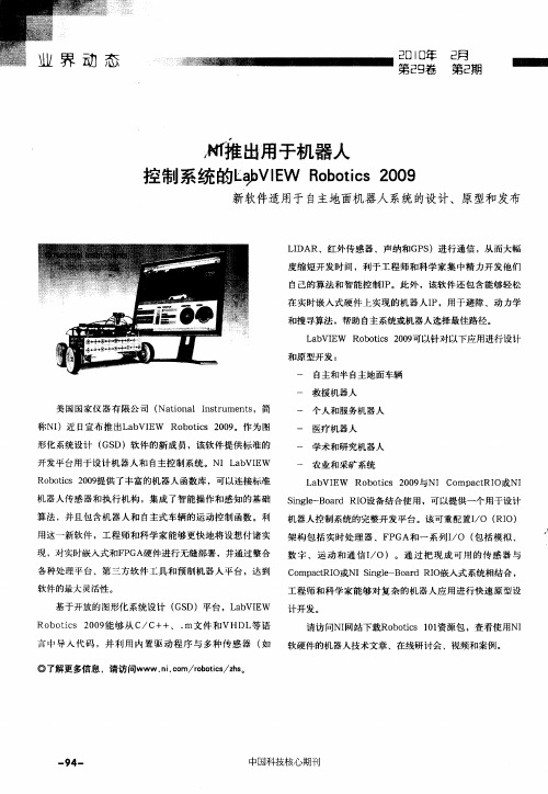
NI推出用于机器人控制系统的LabVIEW Robotics 2009
一
美 国 国家 仪 器 有 限 公 司 ( to a Isr me t ,简 Nain l n tu n s
一
称NI )近 日宣布推 出L b E a VI W R b t s 2 0 。作为 图 o oi 0 9 c 形化系统设计 ( S G D)软 件的新成 员,该 软件提供标 准的
软硬件的机器人技术文章 、在线研讨会 、视频和案 例。
一
9 一 4
中国科技核心期刊
开 发 平 台用 于 设 计 机 器人 和 自主控 制 系 统 。 NI a VI W L b E
一
一
一
R b t s 2 0 提供 了丰 富的机 器人 函数库 ,可以连接标准 o oi 0 9 c 机 器人传感器和执 行机构 ,集成 了智能操 作和感知 的基础 算法 ,并且包含机 器人和 自主式车辆 的运 动控制 函数 。利 用这一新软件 ,工程 师和科 学家能够更快 地将设想 付诸实 现 ,对实时嵌 入式和F GA硬件进行无缝部 署,并通过整合 P
Ro o is 0 9‘够从 C b tc 2 0 H  ̄ /C++、 . m文件 和VHDL 语 等 言 中导 入 代码 ,并 利 用 内置驱 动 程序 与 多种 传感 器 ( 如 ◎了解更多信 息 ,请访 问WWW.i o rbt s zs n. m/o oi / h。 c c 请 访问NI 网站下载Ro ois 0 资源 包 ,查看使用NI b t 1 1 c
数 字 、 运 动 和 通 信 I O) 。通 过 把 现 成 可 用 的 传 感 器 与 /
C mp cRI o at O或NISn l— o r I 嵌 入 式 系统 相 结 合 , ige B ad R O
NI PXIe-1078

NI PXIe-4353
32通道, 24位, 热电偶输入模块
• 32路热电偶输入通道; 8路内置冷端温度补偿通道; 0.3 °C精度 • 90 S/s/通道的采样率 (高速模式); 1 S/s/通道的采样率 (高分辨率模式) • 300 Vrms CAT II通道-地面接地安全隔离 • 自动调零通道用于偏移误差补偿; 热电偶开路检测 • 借由PXI Express, 实现多设备触发和同步 • NI-DAQmx驱动软件和NI LabVIEW SignalExpress LE交互式数据记录软件
NI PXIe-1078
配有交流的9槽3U PXI Express机箱 - 高达1 GB/s
• 5个混合插槽, 3个PXI Express插槽 • 0 °C到50 °C的温度下, 总功率达300 W • 中等性能 – 每插槽高达250 MB/s的带宽和1 GB/s的系统带宽 • 8.43英寸 (214.2 mm) 低深度机箱 - 适用于机架以及台式应用 • 与PXI、PXI Express、CompactPCI和CompactPCI Express模块兼容
双核处理器有两个核心或称计算引擎,配置于同一个处理器中。双核处理器可同时执行两个计算任务,该优势可在多任务环境下得到体 现,例如:允许多个应用程序同时运行的Windows XP。两个应用程序可以同时分别进入处理器的两个核心,从而提高系统整体性能。此 外,双核处理器是NI LabVIEW软件等多线程应用程序的理想选择,应用程序能够将各个任务分为多个线程执行。一个双核处理器可同时 执行众多线程中的两条。 如需配置一个基于NI PXIe-8108的完整PXI Express系统,请访问/pxiadvisor。
NI数据采集(DAQ)设备入门指南说明书
DAQ Getting Started GuideThis guide describes how to confirm your NI data acquisition (DAQ) device is operating properly. Install your application and driver software, then your device, using the instructions packaged with your device. Confirm Device RecognitionComplete the following steps:unch MAX by double-clicking the NI MAX icon on the desktop, or (Windows8) by clickingNI MAX from NI Launcher.2.Expand Devices and Interfaces to confirm your device is detected. If you are using a remoteRT target, expand Remote Systems, find and expand your target, and then expand Devices andInterfaces. If your device is not listed, press <F5> to refresh the configuration tree. If the device isstill not recognized, refer to /support/daqmx.For a Network DAQ device, do the following:•If the Network DAQ device is listed under Devices and Interfaces»Network Devices, right-click it and select Add Device.•If your Network DAQ device is not listed, right-click Network Devices, and select Find Network NI-DAQmx Devices. In the Add Device Manually field, type the Network DAQdevice’s host name or IP address, click the + button, and click Add Selected Devices. Yourdevice will be added under Devices and Interfaces»Network Devices.Note If your DHCP server is set up to automatically register host names, the device registers thedefault host name as cDAQ-<model number>-<serial number>, WLS-<serial number>,or ENET-<serial number>. You can find the serial number on the device. If you cannot find thehost name of that form, it may have been modified from the default to another value.If you still cannot access your Network DAQ device, click the Click here for troubleshootingtips if your device does not appear link in the Find Network NI-DAQmx Devices window orgo to /info and enter the Info Code netdaqhelp.Tip You can test NI-DAQmx applications without installing hardware by using an NI-DAQmxsimulated device. For instructions on creating NI-DAQmx simulated devices and importingNI-DAQmx simulated device configurations to physical devices, in MAX, select Help»Help Topics»NI-DAQmx»MAX Help for NI-DAQmx.3.Right-click the device and select Self-Test. When the self-test finishes, a message indicates successfulverification or if an error occurred. If an error occurs, refer to /support/ daqmx.4.For NI M and X Series PCI Express devices, right-click the device and select Self-Calibrate.A window reports the status of the calibration. Click Finish.Configure the Device SettingsSome devices, such as the NI-9233 and some USB devices, do not need properties for configuringaccessories, RTSI, topologies, or jumper settings. If you are installing only devices without configurable properties, skip to the next step. Configure each device with configurable settings that you install:1.Right-click the device name and select Configure. Be sure to click the device name under thefolder for the system (My System or Remote Systems) and NI-DAQ API in which you want tocontrol the device.For Network DAQ devices, click the device name and then the Network Settings tab to configurenetwork settings. For additional information on configuring Network DAQ devices, refer to yourdevice documentation.2.Configure the device properties.•If you are using an accessory, add the accessory information.•For IEEE 1451.4 transducer electronic data sheet (TEDS) sensors and accessories, configure the device and add the accessory as previously described. Click Scan for TEDS. To configureTEDS sensors cabled directly to a device, in MAX, right-click the device under Devices andInterfaces and select Configure TEDS.3.Click OK to accept the changes.Install Signal Conditioning or Switch DevicesIf your system includes SCXI signal conditioning modules, Signal Conditioning Components (SCC)such as SC carriers and SCC modules, terminal blocks, or switch modules, refer to the getting started guide for the product to install and configure the signal conditioning or switch hardware.Attach Sensors and Signal LinesAttach sensors and signal lines to the terminal block or accessory terminals for each installed device.You can find device terminal/pinout locations in MAX, the NI-DAQmx Help, or the devicedocumentation. In MAX, right-click the device name under Devices and Interfaces, and selectDevice Pinouts.For information about sensors, refer to /sensors. For information about IEEE 1451.4 TEDS smart sensors, refer to /teds. If you are using SignalExpress, refer to Use NI-DAQmx withYour Application Software.Run Test PanelsUse the MAX test panel as follows.1.In MAX, expand Devices and Interfaces or Devices and Interfaces»Network Devices.2.Right-click the device to test, and select Test Panels to open a test panel for the selected device.3.Click the tabs at the top and Start to test the device functions, or Help for operating instructions.4.If the test panel displays an error message, refer to /support.5.Click Close to exit the test panel.DAQ Getting Started Take an NI-DAQmx MeasurementNI-DAQmx Channels and TasksA physical channel is a terminal or pin at which you can measure or generate an analog or digital signal.A virtual channel maps a name to a physical channel and its settings, such as input terminal connections,the type of measurement or generation, and scaling information. In NI-DAQmx, virtual channels areintegral to every measurement.A task is one or more virtual channels with timing, triggering, and other properties. Conceptually, a taskrepresents a measurement or generation to perform. You can set up and save configuration information in a task and use the task in an application. Refer to the NI-DAQmx Help for complete information about channels and tasks.Use the DAQ Assistant to configure virtual channels and tasks in MAX or in your application software. Configure a Task Using the DAQ Assistant from MAXComplete the following steps to create a task using the DAQ Assistant in MAX:1.In MAX, right-click Data Neighborhood and select Create New to open the DAQ Assistant.2.In the Create New window, select NI-DAQmx Task and click Next.3.Select Acquire Signals or Generate Signals.4.Select the I/O type, such as analog input, and the measurement type, such as voltage.5.Select the physical channel(s) to use and click Next. the task and click Finish.7.Configure individual channel settings. Each physical channel you assign to a task receives a virtualchannel name. To modify the input range or other settings, select the channel. Click Details forphysical channel information. Configure the timing and triggering for your task. Click Run. Use NI-DAQmx with Your Application SoftwareThe DAQ Assistant is compatible with version 8.2 or later of LabVIEW, version 7.x or later ofLabWindows™/CVI™ or Measurement Studio, or with version 3 or later of SignalExpress.SignalExpress, an easy-to-use configuration-based tool for data logging applications, is at Start»AllPrograms»National Instruments»NI SignalExpress or (Windows8) NI Launcher.To get started with data acquisition in your application software, refer to the tutorials:Application Tutorial LocationLabVIEW Go to Help»LabVIEW Help. Next, go to Getting Started with LabVIEW»GettingStarted with DAQ»Taking an NI-DAQmx Measurement in LabVIEW.LabWindows/CVI Go to Help»Contents. Next, go to Using LabWindows/CVI»Data Acquisition»Taking anNI-DAQmx Measurement in LabWindows/CVI.Measurement Studio Go to NI Measurement Studio Help»Getting Started with the Measurement StudioClass Libraries»Measurement Studio Walkthroughs»Walkthrough: Creating aMeasurement Studio NI-DAQmx Application.SignalExpress Go to Help»Taking an NI-DAQmx Measurement in SignalExpress.© National Instruments3DAQ Getting Started GuideExamplesNI-DAQmx includes example programs to help you get started developing an application. Modifyexample code and save it in an application, or use examples to develop a new application or add example code to an existing application.To locate LabVIEW, LabWindows/CVI, Measurement Studio, Visual Basic, and ANSI C examples, go to /info and enter the Info Code daqmxexp. For additional examples, refer to .To run examples without hardware installed, use an NI-DAQmx simulated device. In MAX, selectHelp»Help Topics»NI-DAQmx»MAX Help for NI-DAQmx and search for simulated devices. TroubleshootingIf you have problems installing your software, go to /support/daqmx. For hardwaretroubleshooting, go to /support and enter your device name, or go to /kb.If you need to return your National Instruments hardware for repair or device calibration, refer to / info and enter the Info Code rdsenn to start the Return Merchandise Authorization (RMA) process.Go to /info and enter rddq8x for a complete listing of the NI-DAQmx documents and their locations.More InformationAfter you install NI-DAQmx, the NI-DAQmx software documents are accessible from Start»All Programs»National Instruments»NI-DAQ»NI-DAQmx document title or(Windows8) NI Launcher. Additional resources are online at /gettingstarted.You can access online device documentation by right-clicking your device in MAX and selecting Help»Online Device Documentation. A browser window opens to /manuals with the results of a search for relevant device documents. If you do not have Web access, documents for supported devices are included on the NI-DAQmx media.Worldwide Technical SupportFor support information, refer to /support for access to everything from troubleshooting and application development self-help resources to email and phone assistance from NI ApplicationEngineers. Visit /zone for product tutorials, example code, webcasts, and videos.Visit /services for NI Factory Installation Services, repairs, extended warranty, calibration, and other services.To ensure measurement accuracy, NI factory calibrates all applicable hardware and issues a BasicCalibration certificate, which you can get online at /calibration.Visit /training for self-paced training, eLearning virtual classrooms, interactive CDs,Certification program information, or to register for instructor-led, hands-on courses at locations around the world.For support available at the National Instruments worldwide offices, visit , or contact your local office at /contact. National Instruments corporate headquarters is located at 11500 NorthMopac Expressway, Austin, Texas, 78759-3504.DAQ Getting Started Refer to the NI Trademarks and Logo Guidelines at /trademarks for more information onNational Instruments trademarks. Other product and company names mentioned herein are trademarksor trade names of their respective companies. For patents covering National Instrumentsproducts/technology, refer to the appropriate location: Help»Patents in your software, thepatents.txt file on your media, or the National Instruments Patent Notice at /patents.You can find information about end-user license agreements (EULAs) and third-party legal notices inthe readme file for your NI product. Refer to the Export Compliance Information at /legal/export-compliance for the National Instruments global trade compliance policy and how toobtain relevant HTS codes, ECCNs, and other import/export data.© 2003–2013 National Instruments. All rights reserved.373737H-01Jul13。
ADI公司与NI公司联手,共同推出用于ADI Blackfin处理器的LabVIEW嵌入式模块
ADI公司与NI公司联手,共同推出用于ADI Blackfin处理器的LabVIEW嵌入式模块ADI公司和NI公司联合宣布推出用于ADI Blackfin处理器的LabVIEW嵌入式模块的试用版本。
这一产品的推出使得设计工程师能轻松地获得一个无缝的、图形化数据流开发示例,直接部署到ADI Blackfin处理器。
有了这一直观的软件工具,更多工程师可以利用嵌入式技术提高工作效率,并缩短设计至应用所需的时间。
对于与NI的合作,ADI感到非常愉快。
通过将LabVIEW 图形化开发环境和我们最先进的Blackfin处理器以及其他开发工具集成起来,极大地提高了嵌入式设计者的工作效率。
ADI公司集合平台暨服务组总经理Jerry McGuire先生表示全新LabVIEW嵌入式技术所提供的开发环境是行业最顶尖的技术,用于ADI Blackfin处理器的LabVIEW嵌入式模块为域工程师带来了简化的嵌入式编程方式,并为传统设计工程师带来了高层的图形化工具帮助企业缩短产品上市时间。
此次推出的试用版本基于LabVIEW嵌入式技术,并包含Blackfin专属的、hand-opTImized 分析和信号处理功能、集成的I/O(例如视频和音频DAC、ADC和CODEC),以及on-chip 调试功能。
工程师们可以使用直观的图形化数据流开发示例设计他们的应用系统,并将C 代码集成到他们的LabVIEW图例,获得更多的功能。
全新LabVIEW软件通过无缝地集成ADI VisualDSP++开发和调试环境(可实时、直观地进行调试,直接部署至Blackfin处理器),缩短应用所需时间。
用于ADI Blackfin处理器的LabVIEW嵌入式模块的试用版本还能轻松地连接到NI测试测量硬件,在开发过程的初段部署外部仿真和测试算法。
从前,工程师们依赖一小部分专家通过低层的、基于文本的编程语言(例如汇编或C语言)为他们的嵌入式应用编程。
NI研发高级副总裁TIm Dehne先生表示有了用于ADI Blackfin 处理器的LabVIEW嵌入式模块试用版本,NI和ADI将携手帮助更多的工程师和科学家们开发嵌入式应用。
NI提供基于LabVIEW的系统设计与原型创建的工具套件
NI提供基于LabVIEW的系统设计与原型创建的工具套件
佚名
【期刊名称】《电子测试》
【年(卷),期】2003(000)006
【总页数】1页(P119)
【正文语种】中文
【中图分类】G482
【相关文献】
1.NI最新推出针对软件定义的RF测试和原型设计的PXI Express可重配置IF收
发器--新款基于LabVIEW FPGA技术的收发器可在射频应用中引入用户自定义的
IF数据处理 [J], 无
2.NI和TI携手合作,虚拟仪器技术将传统的电源监测效率提高10倍——基于NILabVIEW软件和USB硬件的TI电源优化DSP入门套件提供电源监测功能 [J], 无
3.基于LabVIEW系统与原型创建的工具套件 [J],
4.NI LabVIEW 新添控制设计和仿真工具套件——新型交互式控制设计工具包为开发实时控制系统提供解决方案 [J],
5.NI正式推出LabVIEW20周年纪念版LabVIEW8.20提供与The Math Works,Inc.MATLAB语言语法的兼容性、基于FPGA的快速系统原型设计,以及全新的调制解调工具包 [J],
因版权原因,仅展示原文概要,查看原文内容请购买。
Labview中NI-IMAQdx模块说明
NI-IMAQdx模块说明IMAQdx Snap VI:配置,启动,获取和取消配置单元采集。
在便于编程的应用场合中使用低速或单捕获是必不可少的部分。
如果你调用这个VI之前调用IMAQdx Open Camera VI,IMAQdx Snap VI默认情况下,使用cam0。
如果图像类型与摄像头的视频格式不匹配,该VI将其转换到一个合适的图像类型格式。
Session In:指定您想重新设置的摄像机的名称。
默认值是cam0Session Out:是一个独特的参考相机,与Session In相同IMAQdx Configure Grab VI:配置和开始采集图像.调用IMAQdx Grab VI在缓冲区高速循环采集图像并复制图像。
若在调用IMAQdx Open Camera VI之前调用此VI,则IMAQdx Configure Grab VI默认情况下使用cam0。
调用IMAQdx Unconfigure Acquisition VI取消获取图像的配置。
Session In:指定您想重新设置的摄像机的名称。
默认值是cam0Session Out:是一个独特的参考相机,与Session In相同IMAQdx Grab VI:获取输出图像的当前帧。
在调用IMAQdx Configure Grab VI之后才调用此VI。
如果图像类型与摄像头的视频格式不匹配,该VI将其转换到一个合适的图像类型格式。
Session In:是一个独特的摄像头.可以通过调用IMAQdx Open Camera VI来得到Session Out:是一个独特的参考相机,与Session In相同Wait for Next Buffer?(Yes):若值为“Yes”,驱动程序将等待下一个可用的缓冲区;若值为“No”,将不会等待下一个可用的缓冲区,而是返回到最后采集的缓冲区。
Buffer Number Out:是实际获得的缓冲区的返回值。
- 1、下载文档前请自行甄别文档内容的完整性,平台不提供额外的编辑、内容补充、找答案等附加服务。
- 2、"仅部分预览"的文档,不可在线预览部分如存在完整性等问题,可反馈申请退款(可完整预览的文档不适用该条件!)。
- 3、如文档侵犯您的权益,请联系客服反馈,我们会尽快为您处理(人工客服工作时间:9:00-18:30)。
NI正式推出LabVIEW SignalExpress软件
作者:佚名 文章来源:米醋网 点击数:0 更新时间:2010-1-8
美国国家仪器有限公司(National Instruments,简称NI)正式宣布推出LabVIEW
SignalExpress交互式软件,扩展了其旗舰的LabVIEW图形化系统设计平台,用于简化数据
记录、仪器控制和院校教学应用。LabVIEW SignalExpress基于NI LabVIEW图形化编程的
基本测量、分析和报告功能,为用户控制数百种测量设备提供一个简单易用、拖拉式的使用
方式。
“NI开发的LabVIEW软件让工程师和科学家们可以创建用户自定义的自动化测量应
用。”LabVIEW之父、NI创始人之一暨NI现任商业院士Jeff Kodosky先生表示“LabVIEW
软件平台的新成员LabVIEW SignalExpress,使得我们进一步为用户简化最通用的测量任务,
并提供一个简单的渠道从而完整LabVIEW平台的功能。”
快速创建数据记录系统
工程师和科学家们需要经常构建数据记录系统来采集数据,并存储到硬盘和数据库。现
在只需轻点几下鼠标,他们就可以快速采集到测量结果、将数据记录到硬盘,并导入
Microsoft Excel等电子数据表应用。LabVIEW SignalExpress还提供的数据记录特性包括警
报监控和条件记录等。此外,正因为该软件基于LabVIEW Express技术,工程师们可以简
单地点击鼠标创建LabVIEW图形化编程代码,通过原始的用户界面或增加自定义的逻辑扩
展他们的应用,进行更高级的数据记录应用。
LabVIEW SignalExpress提供与基于USB的模块化数据采集系统CompactDAQ的单次
点击、即插即用的设置并且可用于270余种数据采集仪器。NI CompactDAQ现有30余种模
块选择,帮助用户轻松地结合众多测量,例如RTD、电流I/O、高密度数字I/O、高速模拟
I/O和高精度模拟I/O。NI CompactDAQ USB 即插即用平台与 LabVIEW SignalExpress的结
合能提供一个完整、易用的数据记录解决方案,极大地缩短设置和测量时间。
增加台式测量的效率
使用台式仪器进行重复测量或使用多种仪器测试(例如激励响应测量)通常要手工重复
去调整仪器上的旋钮和按钮。通过LabVIEW SignalExpress,工程师们可以轻松地在400多
种模块化和独立仪器上进行自动化的数据采集、分析和存储。工程师们可以通过使用
LabVIEW SignalExpress节省大量宝贵的实验室工作时间,完成许多通用测量任务的自动化,
例如电路特特性、扫频和数据记录。 工程师们可以使用LabVIEW SignalExpress 中200
多种分析和处理函数,包括频率、时间、静态分析来分析采集到的数据,进一步提高他们的
测量效率。他们可以在采集过程中实时地分析数据,更快地确定测量和设计上的误差,并快
速进行修改以减少重复测量的繁琐。 工程师们现在可以在LabVIEW SignalExpress中自动
生成LabVIEW图形化代码,在生产阶段重复使用他们的测量结果。 理论结合实际,提
高学习效果
现在工程学教授的面对的一个重大挑战就是如何让他们的学生将课堂中学到的理论与实际
应用结合。交互式的LabVIEW SignalExpress环境帮助学生快速预测他们的理论,更好地理
解实际应用。工程学教授可以使用LabVIEW SignalExpress让学生在教室或实验室里,进行
数据采集、分析的上机操作练习,而不是仅教授他们编程理论。