Transient Performance of an Isolated Induction Generator under Unbalanced Loading Conditions
不平衡电网电压下VSG平衡电流控制策略

第55卷第4期2021年4月电力电子技术Power ElectronicsVol.55, No.4April 2021不平衡电网电压下VSG平衡电流控制策略史丽萍,李俊杰,祁晓雨,杨镇泽(中国矿业大学,电气与动力工程学院,江苏徐州221116)摘要:在不平衡电网电压条件下,虚拟同步发电机(VSG)控制面临并网电流不平衡和过流等问题,为此提出一种基于负序电压补偿和峰值电流抑制的VSG平衡电流控制策略。
以负序电流为控制变量,通过准比例谐振(Q PR)控制器产生负序电压,抑制不平衡电流中的负序分量,达到平衡电流的控制目标。
针对电网电压跌落瞬间峰值电流过流问题,通过计算并网电流值与设定值的偏差,并经进一步运算得到动态电压给定,以抑制过大的峰值电流,保证最大峰值电流不超过安全阈值。
实验结果验证了所提控制策略的正确性和有效性。
关键词:虚拟同步发电机;平衡电流控制;准比例谐振控制器中图分类号:TM31 文献标识码:A 文章编号:1000-100X(2021)04-0103-04VSG Balance Current Control Strategy Under Unbalanced Grid VoltageS H I L i-p i n g,L I J u n-j i e,Q I X i a o-yu,YANG Z h e n-z e(China University of Mining and Technology, Xuzhou221116, China)Abstract : In order to solve the problems of grid-connected current unbalance and overcurrent faced by virtual synchronous generator(VSG) control under unbalanced grid voltage conditions,a novel VSG balance current control strategy based on negative sequence voltage compensation and peak current suppression is proposed.To achieve the control goal of balancing current, the negative sequence current is selected as the control variable, the negative sequence voltage which is generated by the quasi proportional - resonant (QPR) controller can suppress the negative sequence in the unbalanced current.For the problem of peak current overcurrent at the moment of grid voltage drop,the deviation of the grid-connected current value and the set value are calculated to generate the dynamic voltage reference which can be used to suppress the excessive peak current and ensure that the maximum peak current does not exceed the safety threshold.The experimental results verified the correctness and effectiveness of the proposed control strategy. Keywords: virtual synchronous generator; balance current control ;quasi proportional-resonant controllerFoundation Project : Supported by National Natural Science Foundation of China (No. 61703404)l引言传统并网逆变器属于静止设备,不能为电网 提供惯性和阻尼支撑,也难以满足对电力系统调 压调频特性的需求。
异步发电机 于平义 仵均科
异步发电机于平义1,仵均科2(1.西安理工大学,陕西西安710048;2.西安微电机研究所,陕西西安710077)摘要:本文论述了异步发电机的分类、结构和工作原理、主要技术指标、设计要点以及典型应用,并给出了异步发电机配套用电力电容器技术数据。
关键词:异步发电机;原理;设计;应用;电力电容器中图分类号:文献标识码:文章编号:Ansynchronous GeneratorY u Pingyi1,Wu Junke2(1. Xi'an Univercity of Technology , Shanxi Xi'an710048,China;2.Xi'an Micro-motor Research Institute, Shanxi Xi'an 710077,China)Abstract: This paper discusses the type, construction and principle, main specification, design outline and representative application of ansynchronous generator, and lists the specification of electric power capacitor for ansynchronous generator.Key words: ansynchronous generator, principles, design, application, electric power capacitor1、分类众所周知,在现代电力系统中,同步发电机一统天下。
但是,在一些小型或微型水电站中,在偏远地区的独立移动电站中,在风力发电站中,异步发电机也得到了普遍应用。
特别是在独立移动电站中,异步发电机,尤其是实心转子三相异步发电机,具有明显的优越性。
不平衡电压下VSG无锁相环并网及运行控制策略

不平衡电压下VSG无锁相环并网及运行控制策略奚鑫泽;徐志;洪灏灏;顾伟【摘要】针对并网逆变器在不平衡电压下电流畸变严重和锁相环节复杂等问题,文中设计了一种基于改进虚拟同步机(VSG)的逆变器无锁相环控制策略.重点研究了VSG在不平衡电网电压下的运行控制方法,设计了一种基于比例积分谐振(PIR)控制器的改进VSG控制策略,在不改变VSG外特性的基础上有效抑制了逆变器输出电流的不平衡分量.同时,提出一种基于虚拟功率的VSG预同步控制策略,保证VSG孤岛转并网模式的无缝切换.整个控制过程不依赖锁相环,避免了锁相环对系统控制精度以及响应速度的影响,降低了控制系统的复杂度.最后,基于RT-LAB的实时仿真平台对所提控制策略进行了验证.【期刊名称】《江苏电机工程》【年(卷),期】2019(038)003【总页数】7页(P80-86)【关键词】虚拟同步机;不平衡电压;平滑切换;无锁相环;RT-LAB【作者】奚鑫泽;徐志;洪灏灏;顾伟【作者单位】云南电网有限责任公司电力科学研究院,云南昆明650217;重庆大学电气工程学院,重庆400044;云南电网有限责任公司电力科学研究院,云南昆明650217;东南大学电气工程学院,江苏南京210096;东南大学电气工程学院,江苏南京210096【正文语种】中文【中图分类】TM7210 引言分布式新能源发电技术是当今研究的热点[1],然而,分布式发电系统缺乏惯性和阻尼,更容易受到功率波动和系统故障的影响[2]。
为了解决这一问题,国内外很多学者都提出了虚拟同步机(virtual synchronous generator,VSG)的概念[3—5]。
通过模拟同步电机的机电暂态方程,使得带有储能的逆变系统具有惯量与阻尼特性,能主动地参与电网的调频调压以及阻尼功率振荡的工作。
目前对于VSG的研究主要针对于三相平衡的系统,然而配电网在故障或者非全相运行等状态下很容易呈现三相电压不平衡的状况。
考虑不平衡磁拉力的双馈异步风力发电机轴承外圈故障动力学建模

考虑不平衡磁拉力的双馈异步风力发电机轴承外圈故障动力学
建模
庞彬;郑涵升;周紫烨;王博巍;郝紫阳
【期刊名称】《电机与控制应用》
【年(卷),期】2024(51)3
【摘要】轴承故障会引起双馈异步风力发电机转子气隙变化,产生不平衡磁拉力(UMP)。
为准确揭示双馈异步风力发电机轴承故障振动特性,开展了考虑UMP的双馈异步风力发电机轴承外圈故障动力学建模研究。
首先,基于赫兹接触理论构建了轴承外圈故障模型;然后,推导了正常和轴承故障下发电机转子的气隙磁密,得到了发电机转子受到的UMP解析式;最后,采用Runge-Kutta法对模型进行求解,得到了轴承故障振动响应。
试验分析表明:所提动力学模型能够有效揭示双馈异步风力发电机轴承故障振动信号的双冲击现象,UMP激励会影响风力发电机轴承外圈故障振动信号的调制特性。
为风力发电机轴承故障诊断提供了新的理论参考。
【总页数】8页(P30-37)
【作者】庞彬;郑涵升;周紫烨;王博巍;郝紫阳
【作者单位】河北大学质量技术监督学院;河北大学计量仪器与系统国家地方联合工程研究中心
【正文语种】中文
【中图分类】TM315
【相关文献】
1.双馈异步风力发电机组定子三相电流不平衡原因分析
2.电网故障下交流励磁双馈风力发电机变流器建模与控制
3.双馈式风力发电机组发电机滚动轴承状态监测及故障诊断方法探究
4.双馈式风力发电机组发电机滚动轴承状态监测及故障诊断方法的分析
5.不平衡电网电压下双馈异步风力发电机组控制策略研究
因版权原因,仅展示原文概要,查看原文内容请购买。
一种双馈风力发电系统低电压穿越控制策略

一种双馈风力发电系统低电压穿越控制策略张阳;黄科元;黄守道【摘要】Through the control of the machine side converter and the grid side converter of wind turbine,which can not only continuous operating,but also can help the grid voltage recovering. Realize the low voltage ride-through (LVRT) during symmetric grid fault. The control target of machine side converter is to realize the maximum wind energy tracking and control of reactive power .The control target of the grid side converter is to ensure the stability of DC bus voltage and control the reactive component of input current. The crowbar protection circuit is employed to ensure the rotor side current and DC bus voltage within the safe range. A speed loop is added based on the original double fed induction generator (DFIG) in this paper, which improve the dynamic performance of the speed and real-time power matching. The system anti impact ability is enhanced and the system stability is improved. The experimental results prove that the LVRT control method of DFIG is effective.%电网电压对称跌落时,通过对机侧变流器和网侧变流器的控制,使得风电机组不仅能够不脱网运行还能对电网提供无功,帮助电网电压恢复,实现双馈风力发电系统的低电压穿越。
论文反激变换器应用
(2-11)
(2-12)
I L1 =
Po U in η
(2-13)
输入电流峰值为
I L1 p =
Po U T + in S D U in ηD 2 L1
(2-14)
2.1.3 电流临界连续模式
电流临界连续模式介于电流连续模式和电流断续模式之间,电感电流波形如图
2-2(c)所示。这种模式下,输出电压和输出电流同时满足式(2-6)和(2-12)。将式(2-6)
代入式(2-12)得
I g = Io =
U inTS N1 U 2T 2 F D(1 − D) = in ON S 2 L1 N 2 2 LU 1 o
(2-15)
其中 I g 为临界连续电感电流。 对(2-15)求极值,可得当占空比 D=0.5 时,临界连续负载电流达到最大值 I g max :
I g max =
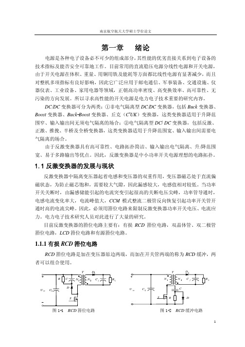
1.1.1 有损 RCD 箝位电路
RCD 箝位电路是加在变压器原边两端,而加在开关管两端的称为 RCD 缓冲,两 者可以组合使用。
T
+
D1
T
D1
N2 C
R C1
C
N1
N2
Cf
RL
+
N1 C1
S
C
f
RL
Hale Waihona Puke U inD SU in
−
−
R
D
图 1-1
RCD 箝位电路
图 1-2
RCD 缓冲电路
1
反激变换器的应用研究
本文重点研究了 RCD 箝位反激变换器稳态原理、参数设计准则及小信号特性, 其次研究了双管反激变换器稳态原理及其参数设计方法,还研究了电流控制技术。其 主要内容分为以下六章: 第一章 分析了中小功率开关电源的理想拓扑,概述了反激变换器发展与现状。 第二章 分析对比了反激变换器三种工作模式及 RCD 箝位电路的设计。 第三章 研究了双管反激变换器稳态工作原理与设计。 第四章 研究了反激变换器小信号特性。 第五章 详细论述了基于电流控制 15W 27VDC/+12V(1.0A) 、-12V(0.25A)RCD 箝位反激变换器机内稳压电源( CCM 模式、 DCM 模式)与 1080W 270VDC/180V(6A)双管反激变换器开关电源的设计过程,给出了试验 结果,并与理论分析进行了比较。 第六章 对本文的工作进行了总结,提出了进一步工作的设想。
一种异步电机全阶磁链观测器设计方法
第29卷第5期水下无人系统学报 Vol. 29No.5 2021年10月 JOURNAL OF UNMANNED UNDERSEA SYSTEMS Oct. 2021收稿日期: 2020-11-02; 修回日期: 2021-01-27.作者简介: 张炜权(1981-), 男, 硕士, 高工, 主要研究方向为流体转动与控制.[引用格式] 贾国涛, 张炜权, 刘国庆. 一种异步电机全阶磁链观测器设计方法[J]. 水下无人系统学报, 2021, 29(5): 596-600.一种异步电机全阶磁链观测器设计方法贾国涛, 张炜权, 刘国庆(中国船舶集团有限公司 第705研究所昆明分部, 云南 昆明, 650101)摘 要: 随着新型水下电动混流泵发射动力技术的不断发展, 对高速电机驱动提出了新的要求。
但传统全阶磁链观测器设计会引发系统极点产生正实部, 造成无速度传感器控制系统不能在低转速区域保持稳定, 促使装置启动失败。
针对此, 文中提出一种新的异步电机全阶磁链观测器设计方法, 设计了一种基于全阶磁链观测器的误差反馈矩阵, 可同时保证观测器极点实部和估计转速传递函数的零点实部都小于零, 从而保证了观测器以及估计转速的稳定。
实验验证了该方法的有效性。
关键词: 异步电机; 全阶磁链观测器; 无速度传感器; 矢量控制; 转速估计中图分类号: TJ630; TM343 文献标识码: A 文章编号: 2096-3920(2021)05-0596-05DOI: 10.11993/j.issn.2096-3920.2021.05.012New Design Method for an Asynchronous Motor Full-Order Flux ObserverJIAGuo-tao , ZHANG Wei-quan , LIU Guo-qing(The 705 Research Institute, China State Shipbuilding Corporation Limited, Kunming 650101, China)Abstract: New technologies for electric underwater mixed-flow pump launch power are increasingly becoming an active research topic in the underwater attack and defense field, in which the reliability design of equipment is the key feature. However, the traditional design method of an asynchronous motor full-order flux observer leads to a positive real part of the poles of the system, resulting in a speed sensorless control system that is not stable in low-speed regions, and, thereby, in the failure of the start-up of the device. This study, therefore, proposes a new design method for an asyn-chronous motor full-order flux observer, which is designed based on a full-order flux observer while ensuring that the real part of the pole of the observer and the real part of the zero point of the estimated speed transfer function are less than zero. As a result, the stability of the observer is ensured while the speed is estimated. Finally, the effectiveness of the method is verified experimentally.Keywords: asynchronous motor; full-order flux observer; speed sensorless; vector control; speed estimation0 引言 为满足水下新型预置式武器平台、深海试验平台、新型潜艇及攻击型无人水下航行器(unman- ned undersea vehicle, UUV)等低噪声、小型化发射的需求, 新型水下电动混流泵发射动力技术越来越成为水下攻防的研究热点, 发射动力装备对高速电机驱动提出了新的要求, 其可靠性设计成为关键技术。
CYME Power Engineering软件解决方案的功能介绍说明书
CYMEPower Engineering Software and SolutionsPower engineering analyses in sync with today’s challenges and technologiesCYME 8.0 leverages the expertise of our extensive customer base and the know-how of our team to bring forth features and analytical capabilities based on users’ needs and trends of the industry.Key features which help you tackle power system studies with ease include:• Integration Capacity Analysis • DER Impact Evaluation• Techno-Economic Analysis • Network Disturbance Assessment D-A-CH-CZ Numerous enhancements havebeen brought to the ProtectiveDevice Analysis module andArc Flash Hazards Assessmentmodule. Analyses such as loadflow, fault analyses, harmonics,dynamic motor start andtransient stability also featuresseveral new functions. TheScripting Tool with Python®has been enhanced with newfunctionalities for further extendthe capability of Python scripts.CYME’s equipment model,such as regulators and cables,continue to be improved toemulate the device’s behavior asaccurately as possible.As it is important to maintaincontinuity between series, itis also essential to progresswith today’s technologies toallow greater user-friendlinesswhich translates into a gain inproductivity for CYME users.CYME 8.0 is equipped with abrand new user interface andwith several enhancementsto the controls and functionsavailable via the Explorer Bar.The combination of newanalyses, user-drivenfunctionalities andimprovements makes CYME8.0 an essential tool for all yourpower engineering studies.Eaton’s CYME is proudto introduce the CYME 8Series, which will investin DER-related tools,look at emerging trendsand continue to focus onnetwork planning andoperation topics. The CYME8.0 introductory versionbrings forth a powerfulframework which connectssimplicity with efficiency,and features engineeringanalyses to address today’schallenges.CYME 8.0 New Features2EATON CYME 8.0 New FeaturesIntegration Capacity Analysis The Integration CapacityAnalysis addresses distributed energy resources (DER) and load interconnection issues by determining the maximum allowable capacity that can be added at any point of the network without violating a set of constraints. This new module allows to quickly assess the hosting capacity of the network and filter out interconnection requests that are non-compliant.Features:•Parameters such as maximum installation capacity, peak and minimum load conditions.•Integration constraints from the California DRP Ruling of May 2016, such as thermal loading, reverse flow,abnormal voltages, voltage variations, protection reduction of reach and sympathetic tripping.DER Impact Evaluation The DER Impact Evaluation module can assist engineers in their generation interconnection system impact studies. The analysis automates a series of time-consuming, repetitive and error-prone verifications and returns insightful results that clearly identify violations.• Multiple loading conditions.•Single or multiple DER installations, with theminimum and maximum DER contribution defined by the user.•Steady-state voltage, voltage variations, thermal loading, reverse power flow on the network due to DER installations are monitored.•Generation and power factor ramping.Network Disturbance Assessment D-A-CH-CZ Based on the standard “Technical Rules for the Assessment of Network Disturbance” published by a German-Austrian-Swiss-Czech working group, the Network Disturbance Assessment D-A-CH-CZ module evaluates the power quality disturbances produced by an equipment on a power source’s signal by determining if the equipment passes three different power quality tests as follows:• Voltage variation analysis • Flicker analysis •Harmonic analysisThe module has the following capabilities:•Take into account different types of installations such as motors, generators, DERs and loads.•Use constraints as per the D-A-CH-CZ™ standard or user-defined.•Display flicker limit-emission curve and harmonic load contribution curve.T echno-Economic Analysis The Techno-Economic Analysis module helps electric utilities invest into their infrastructure by analyzing the technical impacts of modifications made to the network, and the cost they entail. To assist in the determination of the feasibility and the profitability of a project, this new module shows technical and economic data resulting from network modifications such as:The module features:•Cost associated to each network modification.•Economic parameters such as asset cost, operation and maintenance cost.•Technical and economic data output such as loss reduction, reliability improvement, net cash flow and capital budgeting.•Budget management on multi-year time frame when used in conjunction with the CYME Advanced Project Manager module.Protective Device Analysis The Protective Device Analysis module has been enhanced with new functionalities to further its user-friendliness and capabilities.New Explorer Bar control for protective device coordination:•Lists all protective branches in a comprehensive tree view.•Provides an easy access to commands such as display curves and branch device coordination.Additional enhancements include:•The TCC Views can be saved within a study or a self-contained study file.•A TCC Action Bar is displayed in TCC Views.•A simplified coordination report containing only the devices of the selected branch for a branch device coordination.•The coordination of parallel branches connected to a bus instead of assuming radial coordination is supported.•The time current curves of synchronous machine short-time thermal capability, short-circuit decrement and rated full load current are supported.•The motor starting timecurrent curve can be displayed taking into account the data points as calculated by the actual motor starting method of the motor..•The protection level and protection zone color-coding layers have been added Motor starting curves have beenadded to take into account the variation of the starting current over time. It is possible to enter a user-defined curve, or to export the curve from the Dynamic Motor Start analysis module. TCC settings for motors include the Starting Current and the InrushMultiplier.Arc Flash Hazards Assessment The Arc Flash Hazard Analysismodule has been enhanced with new calculation methods while existing methods have been updated, as follows:• IEEE 1584™ 2011 is now supported.• The default clothingguide reflects the PPE recommended by the NFPA-70E© 2015 standard.• New calculation method based on the Wilkins method is now available. The Lee method is now available for both Industrial and Distribution Analyses.• A new method based on the 2013 OSHA tables has been added to calculate the cal system.• The Minimum Approach Distance values have been updated according to the 2012 edition of the NESC© Standard.Other enhancements include:• The Multiple Contributions option calculates the total incident energy from different contributing energy sources connected to the analyzed node.• A Backup Protection option allows selecting the fastest protective device according to the time-current curves of the devices available at a given simulation.• The duration of the contributions from induction machines and inverter-based DGs can be specified.• Additional calculations with LG current for methods in the industrial system analyses can be performed.• New Arc Flash result box. • New reports: Summary by Protective Device and a Summary by Network report.Load Flow Analysis• Improvement to theperformance of the Newton-Raphson-Unbalanced method.Fault Analysis• Simultaneous Fault – A newdiagram is available whencreating an inter-circuit fault toillustrate the interconnectiondiagram with the respectivefault type for each circuit to besimulated.• Device monitoring in ANSIand IEC 60909© Short-Circuitanalyses for first ring andremote contributions whenfaulting all buses and nodes issupported.• ANSI test X/R ratios for lowvoltage protective devicesare included the databaselibrary and are factored in theanalysis for the calculationof the short circuit dutymultiplying factors of thosedevices.• Conventional short-circuitanalysis device rating Reportfor the interrupting duty sizingof protective devices such asbreakers and fuses has beenadded.• Equipment Rating Verification– The summary report hasbeen enhanced to includeall monitored devices and tocolor-code each one basedon its pass or fail status. ABus Rating report detailingoverloads and short-circuitrating has also been added.Harmonic Analysis• Now supports the 2014version of the IEEE© standardfor Voltage Distortion Limitsand Current Distortion Limits.Dynamic Motor Starting• The acceleration torquecalculated after running aDynamic Motor Start analysiscan be monitored and plotted.• The motor staring timecurrent curve data sets canbe updated with the resultsof any starting assistancemethod supported in theanalysis.T ransient Stability Analysis• A new feature has been addedto report over-frequency,under-frequency and voltagedips.• A new Alerts Report section,with alerts on synchronousgenerators and on systembuses, is added to flagviolations to any particularoperating standards.Scripting T ool with Python®The Python Scripting tool hasbeen enhanced with newfunctionalities to further extendPython scripts capability to meetyour analytical needs.• An integrated help has beenincluded in the CYME PythonEditor for access to a fulldocumentation page onall the objects/functions ofthe CYME Python interfacein a single click. The Auto-Save functionality has beenintroduced in the PythonEditor to avoid losing data.• The CymPy library nowprovides complete accessto the charts generated byany simulation in the CYMEsoftware.• Customized charts can becreated through the CymPylibrary.• New features are added in theCYME Python Editor to allowthe use of nested views andload models.3EATON CYME 8.0 New FeaturesFollow us on social media to get thelatest product and support information.Eaton is a registered trademark. All other trademarks are property of their respective owners.Eaton1000 Eaton Boulevard Cleveland, OH 44122United States CYME International T&D 1485 Roberval, Suite 104St.Bruno, QC, Canada J3V 3P8P: 450.461.3655 F: 450.461.0966P: 800.361.3627 (Canada/USA)******************/cyme© 2017 Eaton All Rights Reserved Printed in CanadaPublication No. BR 917 065 EN February 2017CYME 8.0 New FeaturesPower engineering analyses in sync with today’s challenges and technologiesEquipment Enhancements•Regulator – Distinct by-phase bandwidths for both theforward settings and reverse settings have been added.•Cable – An estimate function for the number of conductor strands has been added to the cable construction details.•Equipment Import / Export – It is now possible to import and export one or more pieces of equipment using XML files.One-Line Diagram Navigation and ViewsSeveral improvements have been made functions related to the One-Line Diagram navigation and views, such as:•A new Circle Symbol function to circle individual devices.•The Background Map Control, used by the Geographic Overlay module and the Online Maps Service, has been enhanced to enable the display of different map types simultaneously.•The main line of a radial circuit can be defined by the user, color-coded on the one-line diagram and used to restrict the scope of some analyses. •A color map, based on color grid aggregation methods, is now available.•New network modeling mode facilitates addition of new devices on the one-line diagram.User Interface Improvements The user-interface is equipped with various enhancements to further its user-friendliness and intuitiveness. Among those:•Windows and controls can be docked at any selected location within the framework.•A new explorer bar control to edit the properties of the element selected on the one-line diagram.•A new action bar provides a contextual layout ofcommands and options based on the active view.•A new CustomizeCommands interface for the personalization of software commands available in menus and toolbars.•New layout for the Customize Menu and Customize Toolbar dialog boxes to facilitate their use.•A start-up page offers quick access to commands such as opening a study/tutorial and connecting to a database.Reports Enhancements The spreadsheet reports have been greatly enhanced both esthetically and functionally as they are now equipped with many new tools toprovide additional flexibility for customization and clarity in the information displayed.•Sorting, decimals, grouping filtering, conditional formatting cell resizing and search have been enhanced.•Multiple layouts can be saved for a given report. Hyperlinks to the one-line displayelements have been added inreports.。
不平衡电网下双dq坐标变换的M3C微分平坦控制策略
第28卷㊀第1期2024年1月㊀电㊀机㊀与㊀控㊀制㊀学㊀报Electri c ㊀Machines ㊀and ㊀Control㊀Vol.28No.1Jan.2024㊀㊀㊀㊀㊀㊀不平衡电网下双dq 坐标变换的M3C 微分平坦控制策略程启明,㊀杜婷伟,㊀赖宇生(上海电力大学自动化工程学院,上海200090)摘㊀要:针对目前模块化多电平矩阵变换器(M3C )研究中常用的双αβ坐标变换解耦不彻底㊁传统PID 控制方法效果差㊁不平衡工况研究少等问题,在分析拓扑结构和数学模型的基础上,采用双dq 坐标变换对电气量进行解耦,建立了M3C 的输入输出侧数学模型,分别对电压㊁电流进行正负序分离,并结合微分平坦理论,推导了输入侧㊁输出侧的微分平坦控制(DFC ),最后模拟了两种不平衡工况下的运行情况㊂仿真结果表明,与线性PID 控制相比,非线性的微分平坦控制提高了内环电流的跟踪速度和精度,更适用于非线性的M3C 系统㊂在电网平衡或电网出现不对称故障时,微分平坦控制下M3C 系统的动态稳定性与快速性更好,电能质量更高,电流谐波含量最多可以降低1.42%,能够更有效地抑制负序电流㊂关键词:海上风力发电;模块化多电平矩阵变换器;不平衡电网;双dq 坐标变换;微分平坦控制;PID 控制DOI :10.15938/j.emc.2024.01.005中图分类号:TM762文献标志码:A文章编号:1007-449X(2024)01-0049-12㊀㊀㊀㊀㊀㊀㊀㊀㊀㊀㊀㊀㊀㊀㊀㊀㊀㊀㊀㊀㊀㊀㊀㊀㊀㊀㊀㊀㊀㊀㊀㊀㊀㊀㊀㊀㊀㊀㊀㊀㊀㊀㊀㊀㊀㊀㊀㊀㊀㊀㊀㊀㊀㊀㊀㊀㊀㊀㊀㊀㊀㊀㊀㊀㊀㊀㊀㊀㊀㊀㊀㊀㊀㊀㊀㊀㊀㊀㊀㊀㊀㊀㊀㊀㊀㊀㊀㊀㊀㊀㊀㊀㊀㊀㊀㊀㊀㊀㊀㊀㊀㊀㊀㊀㊀㊀㊀㊀㊀㊀收稿日期:2022-12-09基金项目:国家自然科学基金(62303301);上海市电站自动化技术重点实验室资助项目(13DZ2273800)作者简介:程启明(1965 ),男,博士,教授,研究方向为电力系统自动化㊁发电过程控制㊁先进控制及应用;杜婷伟(2000 ),女,硕士研究生,研究方向为新能源发电控制㊁海上风力发电控制;赖宇生(1996 ),男,硕士研究生,研究方向为新能源发电控制㊁电力电子控制㊂通信作者:杜婷伟Differential flatness control strategy of modular multilevel matrix converter based on double dq coordinate transformation underunbalanced grid conditionsCHENG Qiming,㊀DU Tingwei,㊀LAI Yusheng(College of Automation Engineering,Shanghai University of Electric Power,Shanghai 200090,China)Abstract :Aiming at the problems of incomplete decoupling of double αβcoordinate transformation com-monly used in modular multilevel matrix converter (M3C)research,on the basis of the analysis of topol-ogical structure and mathematical model,poor effect of traditional PID control method,and little research on unbalanced working conditions,etc.,double dq coordinate transformation was adopted to decouple the electrical quantity.The mathematical model of M3C s input and output side was established,the voltage and current were separated in positive and negative order,and the differential flatness control (DFC)of the input side and the output side was derived by combining the differential flatness theory.Finally,the operation under two unbalanced conditions was pared with linear PID control,the simula-tion results show that nonlinear differential flat control improves the tracking speed and accuracy of innerloop current,and is more suitable for nonlinear M3C system.When the power grid balance or asymmetricfault occurs,M3C system under differential flat control has better dynamic stability and rapidity,higher power quality,and can suppress negative sequence current more effectively.The current THD can be re-duced by up to1.42%.Keywords:offshore wind power;modular multilevel matrix converter;unbalanced grid;double dq coor-dinate transformation;differential flatness control;PID control0㊀引㊀言随着气候变暖㊁环境恶化等导致能源危机,新型清洁能源已成为了国家经济发展的方向之一[1-2]㊂其中海上风电由于具备稳定性强㊁可再生㊁受环境影响小等优势,极具开发前景㊂但如何将海上发电厂并入主电网正成为国内外海上风电领域的研究重点[3-4]㊂与常规的50Hz的高压交流输电[5]和高压直流输电[6]相比,50/3Hz的低频交流输电,又称分频传输系统,具有显著优势:可以提高交流海缆输电能力,只需一个AC/AC换流站,且设备投资成本少[7-9]㊂在现有的AC/AC变换设备中,模块化多电平矩阵变换器(modular multilevel matrix converter, M3C)[10]由Erickson R.和AI-Naseem O.于2001年提出,作为直接AC/AC变换器具有高电压㊁大容量的优点㊂M3C拓扑由9条桥臂构成,以3ˑ3矩阵形式排布,每条桥臂的电压㊁电流分量均包含两种不同频率的交流分量,存在强耦合现象,控制难度大㊂目前国内外学者已经对M3C的控制策略开展了一些研究,最为普遍应用的是基于双αβ0坐标变换的解耦控制方法㊂文献[11]的αβ0变换方法仅能将M3C的输入电流和输出电流解耦㊂文献[12-14]提出双αβ0变换,能将桥臂电流中的输入电流㊁输出电流和环流完全解耦,同时增加了两个对角维度的平衡控制,控制桥臂能量均衡分布㊂文献[15]将预测控制用于M3C中,然而M3C包含大量的状态变量,导致参数复杂㊁计算量庞大不具有实用性㊂文献[16-17]研究了双αβ0变换的非线性无源控制和微分平坦控制,系统跟踪速度有很大提升㊂尽管双αβ0变换被广泛采纳,但是这种控制方案也存在缺点,其被控量都是交流量,物理概念易混淆,且功率分量计算复杂㊂文献[18]提出了双dq坐标变换的方法,采用直流量作为内环被控量,但其采用的PID控制不仅调参复杂,而且是线性控制方法,作用在非线性的M3C上并不能使系统迅速稳定㊂到目前为止,采用双dq解耦方法的研究较少,并且其中未有文献考虑在发生不平衡故障时的非线性控制方案㊂非线性的微分平坦控制(differential flatness control,DFC)对系统稳定性的提升,超调量的降低等方面颇具优势,在电力电子领域和清洁能源领域已成为了研究热点[19-20]㊂与线性PID控制相比, DFC控制能使M3C系统稳定运行,避免因内外部扰动而发生动态特性变差的现象,提高内环电流的跟踪速度和精度㊂本文首次提出在不平衡电网下将微分平坦控制策略应用到基于双dq坐标变换的M3C控制中㊂首先给出M3C的拓扑结构与工作原理,建立M3C在双dq坐标变换下的数学模型,然后在输入侧与输出侧出现不对称故障时,将电压电流正负序分离,进一步运用微分平坦理论,设计输入侧㊁输出侧的DFC控制器㊂最后,在MATLAB/Simulink平台上建立两种不平衡工况,分别模拟DFC控制和传统PID控制,通过仿真验证在电网电压不平衡条件下,采用DFC控制能使系统稳定运行,且效果优于传统PID 控制㊂1㊀M3C的电路结构及数学模型M3C变换器的主电结构如图1所示㊂M3C以H全桥子模块(用SM表示,由T1~T44个IGBT和1个电容组成)为基本单元,等效电阻R㊁电感L以及n个子模块级联构成1个换流桥臂,共有9个桥臂,可分为3个子换流器㊂M3C的输入侧是低频三相交流电源,输出侧是工频三相交流电源㊂图1中:输入侧交流电压为u su㊁u sv㊁u sw,电流为i u㊁i v㊁i w;输出侧交流电压为u1a㊁u1b㊁u1c,电流为i a㊁i b㊁i c;桥臂电流为i xy,桥臂总电容电压为u c xy(x=u㊁v㊁w,y=a㊁b㊁c),u NO为共模电压㊂可以将每个桥臂的子模块视为受控电压源,得到图2所示的简化结构图㊂05电㊀机㊀与㊀控㊀制㊀学㊀报㊀㊀㊀㊀㊀㊀㊀㊀㊀㊀㊀㊀㊀第28卷㊀图1㊀M3C 拓扑结构Fig.1㊀Topology ofM3C图2㊀M3C 的简化结构图Fig.2㊀Simplified structure diagram of M3C分析图2所示的输入侧㊁输出侧的电压㊁电流关系,由Kirchhoff 定律建立回路电压方程可得:u su =Ri uy +L d iuy d t +u uy +u 1y +u NO ;u sv =Ri vy +L d i vyd t +u vy +u 1y +u NO ;u sw =Ri wy +L d i wyd t+u wy +u 1y +u NO ㊂üþýïïïïïï(1)i a +i b +i c =0;i u +i v +i w =0㊂}(2)对式(1)进行αβ0坐标变换,可将两种频率分量解耦,得到3个子换流器的电压电流关系为:u s αu s βéëêêùûúú=R +L d d t ()i αa i βa éëêêùûúú+u αa u βa éëêêùûúú;u s αu s βéëêêùûúú=R +L d d t ()i αb i βb éëêêùûúú+u αb u βb éëêêùûúú;u s αu s βéëêêùûúú=R +L d d t ()i αc i βc éëêêùûúú+u αc u βc éëêêùûúú㊂üþýïïïïïïïï(3)u so u so u so éëêêêùûúúú=R +L d d t ()i oa i ob i oc éëêêêùûúúú+u oa u ob u oc éëêêêùûúúú+3u 1a u 1b u 1c éëêêêùûúúú+3u NO u NO u NO éëêêêùûúúú㊂(4)当输入输出系统三相对称时,可忽略零序分量,对式(4)进行第2次αβ0坐标变换可得0[]=R +Ld d t()i o αi b βéëêêùûúú+u o αu o βéëêêùûúú+3u 1αu 1βéëêêùûúú㊂(5)式(3)与式(5)为M3C 在αβ坐标系下的数学模型㊂其中:式(3)为输入侧电压㊁电流αβ分量,其频率仅与输入侧频率相同;式(5)为输出侧电压㊁电流αβ分量,其频率仅与输出侧频率相同㊂由此实现了桥臂电压电流的解耦㊂对式(3)㊁式(5)分别采用各自频率的dq 坐标变换,可得M3C 在双dq 坐标系下的数学模型为:u da u qa éëêêùûúú=u sd u sq éëêêùûúú-R +L d d t ()i da i qa éëêêùûúú-ωs L -i qa i da éëêêùûúú;u db u qb éëêêùûúú=u sd u sq éëêêùûúú-R +L d d t ()i db i qb éëêêùûúú-ωs L -i qb i db éëêêùûúú;u dc u qc éëêêùûúú=u sd u sq éëêêùûúú-R +L d d t ()i dc i qc éëêêùûúú-ωs L -i qc i dc éëêêùûúú;u od u oq éëêêùûúú=-3u 1d u 1q éëêêùûúú-R +L d d t ()i od i oq éëêêùûúú-ω1L -i oq i od éëêêùûúú㊂üþýïïïïïïïïïïïï(6)式中:ωs 表示输入侧频率;ω1表示输出侧频率㊂由M3C 换流器稳态工作时的对称性可知i da i qa éëêêùûúú=i db i qb éëêêùûúú=i dc i qc éëêêùûúú=13i sd i sq éëêêùûúú㊂(7)式中i sd ㊁i sq 分别为输入侧电流的d㊁q 分量㊂由坐标变换原理可得,桥臂电流在dq 坐标下的输出侧频率分量满足下式:i 1d i 1q éëêêùûúú=3i od i oq éëêêùûúú㊂(8)式中i 1d ㊁i 1q 分别为输出侧电流的d㊁q 分量㊂对输出侧电压d㊁q 分量进行逆坐标变换,可得桥臂电压的输出侧频率分量如下:u oau ob u oc éëêêêùûúúú=T αβ/abc T dq /αβ-1u od u oqéëêêùûúú㊂(9)式中T dq /αβ㊁T dq /αβ-1为输出侧的逆坐标变换矩阵㊂15第1期程启明等:不平衡电网下双dq 坐标变换的M3C 微分平坦控制策略将桥臂电压中的输入㊁输出频率分量叠加,可将桥臂电压表示如下:u ua u va u wa éëêêêùûúúú=T αβ/abc T dq /αβ-s u da u qa éëêêùûúú+u oa u oa u oa éëêêêùûúúú;u ub u vb u wb éëêêêùûúúú=T αβ/abc T dq /αβ-s u db u qb éëêêùûúú+u ob u ob u ob éëêêêùûúúú;u uc u vc u wc éëêêêùûúúú=T αβ/abc T dq /αβ-s u dc u qc éëêêùûúú+u oc u oc u oc éëêêêùûúúú㊂üþýïïïïïïïïïïïïïï(10)式中T dq /αβ-s 为输入侧的逆坐标变换矩阵㊂2㊀不平衡电网下微分平坦控制策略在不平衡工况下,M3C 系统中会出现负序分量,导致过电流和非特征谐波的产生,影响控制效果,甚至烧毁元器件,对系统的安全稳定运行造成威胁,所以本文旨在研究基于M3C 系统在不对称故障条件下的控制策略㊂图3为不平衡电网下M3C 的总体控制结构图,其控制策略包括输入侧控制㊁输出侧控制㊁正负序分离㊁功率控制㊁桥臂分层直流稳压控制以及载波移相调制㊂图3㊀M3C 的整体控制结构图Fig.3㊀General control structure diagram of M3C1)正负序分离:运用双dq 坐标变换对输入侧和输出侧的电压㊁电流进行解耦,然后分别计算出正㊁负序电压电流分量;2)功率控制:根据不平衡工况下M3C 的运行要求,引入功率控制来求解期望电流值;3)输入/输出侧控制:基于微分平坦理论,推导出输入侧㊁输出侧的DFC 控制器;4)子模块独立均压控制:用于平衡桥臂的子模块电容电压,此控制有利于保证系统的安全稳定运行㊂2.1㊀正负序分离当三相系统不对称时,系统中将会出现负序分量,导致系统出现过电流,会严重威胁整个系统的安全稳定运行[21]㊂因此,需要分离电气量中的正㊁负序分量,分别提取电压㊁电流的正序分量和负序分量,再设计相应的正㊁负序的控制策略㊂由于篇幅限制,本文仅以输入侧为例,系统的电压㊁电流可表示为f uvw=f u f v f w éëêêêùûúúú=f +cos βf +(cos β-2π/3)f +(cos β+2π/3)éëêêêùûúúú+f-cos γf -(cos γ+2π/3)f-(cos γ-2π/3)éëêêêùûúúú+f 0f 0f 0éëêêêùûúúú㊂(11)式中:β=ω+t +α+,ω+=ωs ;γ=ω-t +α-,ω-=-ωs ;α+㊁α-分别为正㊁负序分量的初相角;f uvw 表示输入侧系统的电压或电流;f +㊁f -分别为正㊁负序分量的幅值;f 0为零序分量㊂本文系统为三相三线制,无零序回路,所以可以忽略零序分量㊂三相坐标系向两相旋转坐标系转换的正负序矩阵分别为:T +=23cos ωt cos(ωt -2π/3)cos(ωt +2π/3)-sin ωt -sin(ωt -2π/3)-sin(ωt +2π/3)[];T -=23cos ωt cos(ωt +2π/3)cos(ωt -2π/3)sin ωtsin(ωt +2π/3)sin(ωt -2π/3)[]㊂üþýïïïï(12)对式(11)进行正负序dq 变换可得:f ᶄ+d f ᶄ+q éëêêùûúú=f +cos α+f +sin α+éëêêùûúú+f -cos(2ω+t +α-)-f -sin(2ω+t +α-)éëêêùûúú;f ᶄ-d f ᶄ-qéëêêùûúú=f -cos α-f -sin α-éëêêùûúú+f +cos(2ω-t +α+)-f +sin(2ω-t +α+)éëêêùûúú㊂üþýïïïïïï(13)将式(13)延迟π/2,可得25电㊀机㊀与㊀控㊀制㊀学㊀报㊀㊀㊀㊀㊀㊀㊀㊀㊀㊀㊀㊀㊀第28卷㊀f ᶄ+d f ᶄ+q f ᶄ-d f ᶄ-qéëêêêêêùûúúúúúe -jπ2=-f +sin α+-f -sin(2ω+t +α-)f +cos α+-f -cos(2ω+t +α-)-f -sin α--f +sin(2ω-t +α+)f -cos α--f +cos(2ω-t +α+)éëêêêêêùûúúúúú㊂(14)联立式(13)和式(14)可将正负序分离如下:f +d f +q f -d f -q éëêêêêêùûúúúúú=12f ᶄ+d +f ᶄ+q exp(-jπ/2)f ᶄ+q-f ᶄ+d exp(-jπ/2)f ᶄ-d +f ᶄ-q exp(-jπ/2)f ᶄ-q-f ᶄ-dexp(-jπ/2)éëêêêêêùûúúúúú㊂(15)2.2㊀功率控制根据瞬时无功功率理论,可将瞬时有功功率和无功功率表示为:P =P 0+P s2sin(2ωt )+P c2cos(2ωt );Q =Q 0+Q s2sin(2ωt )+Q c2cos(2ωt )㊂}(16)式中:P 0是有功功率的直流分量;Q 0是无功功率的直流分量;P s2为有功功率的正弦2倍频分量;P c2为有功功率的余弦2倍频分量;Q s2为无功功率的正弦2倍频分量;Q c2为无功功率的余弦2倍频分量㊂将式(16)整理后,其矩阵形式如下:P 0P s2P c2Q 0Q s2Q c2éëêêêêêêêêùûúúúúúúúú=u +sd u +squ -sdu -sq u -sq -u -sd -u +sq u +sd u -sd u -sq u +sd u +sq u +sq -u +sd u -sq -u -sd -u -sd-u -sq u +sd u +squ -sq-u -sdu +sq -u +sdéëêêêêêêêêêùûúúúúúúúúúi +sdi +sq i -sd i -sq éëêêêêêùûúúúúú㊂(17)根据常见不平衡工况的负面影响,可将系统控制目标设为:1)平衡电网电流;2)消除有功功率纹波;3)消除无功功率纹波㊂对应的电流期望值分别如下:i +sdref =u +sdP 0+u +sqQ 0u +2sd+u +2sq ,i -sdref =0;i +sqref=u +sq P 0-u +sd Q 0u +2sd +u +2sq,i -sqref =0㊂üþýïïïï(18)i +sdref i +sqref i -sdref i -sqref éëêêêêêùûúúúúú=u +sd u +squ -sd u -sq u +sq -u +sdu -sq-u -sd -u -sd -u-squ+sdu +sq u -sq-u -sdu +sq-u +sdéëêêêêêùûúúúúú-1P 0Q 0Q s2Q c2éëêêêêêùûúúúúú;(19)i +sdref i +sqref i -sdref i -sqref éëêêêêêùûúúúúú=u +sdu +sq u -sd u -sq u +sq -u +sd u -sq-u -sd u -sq -u -sd -u +sq u +sd u -sdu -squ +sdu +sqéëêêêêêùûúúúúú-1P 0Q 0P s2P c2éëêêêêêùûúúúúú㊂(20)2.3㊀输入/输出侧平坦控制微分平坦控制多用于连续时间的非线性控制系统中,能快速㊁准确地跟踪参考值,主要由前馈期望量和误差反馈补偿量组成,其理论框图如图4所示㊂首先分析微分平坦理论的基本原理㊂图4㊀微分平坦控制策略框图Fig.4㊀Block diagram of DFC control strategy设非线性系统为:x ㊃=f (x ,u ),x ɪR n ,u ɪR m ;y =g (x ),y ɪR n ㊂}(21)式中u ㊁y ㊁x 分别为系统的输入变量㊁输出变量和状态变量㊂微分平坦理论的判断条件为:x =x (y ,y ㊃, ,y (λ1));u =u (y ,y ㊃, ,y(λ2))㊂}(22)式中λ1㊁λ2均为正整数,它们分别为状态变量㊁输入变量的微分阶数㊂微分平坦控制策略框图如图4所示:u ref,c 为前馈控制量;u ref,b 为误差反馈补偿值;u ref 为参考输入量;y 为输出实际值;y ref 为其期望值;Δy 为两者误值;Δy ref 为Δy 的期望值㊂由于3个子换流器的结构相同,控制器也相同,本文仅以a 相的子换流器为例具体分析㊂另外,正㊁负序分量的控制类似,在此仅推导正序分量的控制过程㊂根据式(6),可以推出输入侧正序的平坦控制器的前馈控制量为u +da_ref,c u +qa_ref,c éëêêùûúú=u +sd u +sq éëêêùûúú-R +L d d t ()i +da_ref i +qa_ref éëêêùûúú-ωs L -i +qa_ref i +da_ref éëêêùûúú㊂(23)35第1期程启明等:不平衡电网下双dq 坐标变换的M3C 微分平坦控制策略式中u +da_ref,c ㊁u +qa_ref,c 分别为输入电流参考值i +da_ref ㊁i +qa_ref 生成的前馈控制量㊂将系统状态变量误差表示为:Δi +da =i +da -i +da_ref ;Δi+qa=i+qa-i+qa_ref㊂}(24)将式(24)代入式(6),可得误差模型如下:Δu +da Δu +qa éëêêùûúú=-R +L d d t()Δi +da Δi +qa éëêêùûúú-ωs L -Δi +qa Δi +da éëêêùûúú㊂(25)由式(25)可得相应误差反馈补偿值为Δu +da_ref,b Δu +qa_ref,b éëêêùûúú=-k DFp +k DFi s ()Δi +da_ref -Δi +da Δi +qa_ref -Δi +qa éëêêùûúú-ωs L -Δi +qa Δi +da éëêêùûúú㊂(26)式中:k DFp ㊁k DFi 为PI 参数;u +da_ref,b ㊁u +qa_ref,b 分别为Δi +da㊁Δi +qa与参考值生成的误差反馈补偿值㊂令Δi +da_ref =0,Δi +qa_ref =0,可得Δu +da_ref Δu +qa_ref éëêêùûúú=Δu +da_ref,b Δu +qa_ref,b éëêêùûúú+Δu +da_ref,c Δu +qa_ref,c éëêêùûúú㊂(27)联立式(6)和式(27)可得(R +Ls )Δi +da_refΔi +qa_ref éëêêùûúú-k DFp +k DFis ()i +da-i +da_refi +qa -i +qa_ref éëêêùûúú=(R +Ls )i +dai +qa éëêêùûúú㊂(28)由式(28)可得d㊁q 轴电流的闭环传递函数如下:H d (s )H q (s )éëêêùûúú=i+dai+da_refi+qai +qa_ref[]T=11[]㊂(29)因此,上述设计的M3C 平坦控制器能实现电气量的解耦,响应速度快,跟踪效果好㊂类似地,可以推导出输入侧b 相子换流器㊁c 相子换流器以及输出侧的正序前馈控制量㊁误差反馈补偿量和平坦控制器分别为:u +db_ref,c u +qb_ref,c éëêêùûúú=u +sd u +sq éëêêùûúú-R +L d d t ()i +db_ref i +qb_ref éëêêùûúú-ωs L -i +qb_ref i +db_ref éëêêùûúú;(30)Δu +db_ref,b Δu +qb_ref,b éëêêùûúú=-k DFp +k DFis ()Δi +db_ref -Δi +db Δi +qb_ref -Δi +qb éëêêùûúú-ωs L -Δi +qb Δi +db éëêêùûúú;(31)Δu +db_ref Δu +qb_ref éëêêùûúú=Δu +db_ref,b Δu +qb_ref,b éëêêùûúú+Δu +db_ref,c Δu +qb_ref,c éëêêùûúú;(32)u +dc_ref,c u +qc_ref,c éëêêùûúú=u +sd u +sq éëêêùûúú-R +L d d t ()i +dc_ref i +qc_ref éëêêùûúú-ωs L -i +qc_ref i +dc_ref éëêêùûúú;(33)Δu +dc_ref,b Δu +qc_ref,b éëêêùûúú=-k DFp +k DFis ()Δi +dc_ref -Δi +dc Δi +qc_ref -Δi +qc éëêêùûúú-ωs L -Δi +qc Δi +dc éëêêùûúú;(34)Δu +dc_ref Δu +qc_ref éëêêùûúú=Δu +dc_ref,b Δu +qc_ref,b éëêêùûúú+Δu +dc_ref,c Δu +qc_ref,c éëêêùûúú;(35)u +od_ref,c u +oq_ref,c éëêêùûúú=-3u +1d u +1q éëêêùûúú-R +L d d t ()i +od_ref i +oq_ref éëêêùûúú-ω1L -i +oq_ref i +od_ref éëêêùûúú;(36)Δu +od_ref,b Δu +oq_ref,b éëêêùûúú=-k DFp +k DFi s ()Δi +od_ref -Δi +od Δi +oq_ref -Δi +oq éëêêùûúú-ωs L -Δi +oq Δi +od éëêêùûúú;(37)Δu +od_ref Δu +oq_ref éëêêùûúú=Δu +od_ref,b Δu +oq_ref,b éëêêùûúú+Δu +od_ref,c Δu +oq_ref,c éëêêùûúú㊂(38)M3C 输入侧㊁输出侧正序平坦控制的详细框图如图5所示㊂2.4㊀子模块独立均压控制本文采用子模块独立均压控制使各子模块的电容电压达到稳定㊁均衡,其具体原理为:通过每个桥臂上的电流㊁对应桥臂的直流电压㊁单个子模块的电容电压,结合输入侧㊁输出侧的平坦控制信号,得出最终的桥臂控制信号,再送入载波移相调制,以此保证子模块电容电压的稳定㊂控制框图见图6㊂以桥臂u a 为例,其总电容电压u Cua ,子模块平均电容电压为u -Cua ,调制信号为u ∗ua ,第j 个子模块的45电㊀机㊀与㊀控㊀制㊀学㊀报㊀㊀㊀㊀㊀㊀㊀㊀㊀㊀㊀㊀㊀第28卷㊀电容电压为u Cua j㊂图5㊀M3C 系统的微分平坦控制框图Fig.5㊀DFC control block diagram of M3Csystem图6㊀子模块独立均压控制Fig.6㊀Independent and average voltage control ofsub-module3㊀仿真实验分析本文在MATLAB /Simulink 仿真平台上对图1所示M3C 系统进行了模拟㊂由此设计了两种不平衡故障工况,分别仿真了微分平坦控制与传统的PID 控制,并对比仿真效果㊂系统仿真参数如表1所示㊂表1㊀系统仿真实验参数Table 1㊀Parameters of system simulation experiment㊀㊀参数数值输入侧电压幅值/kV 10输出侧电压幅值/kV 10输入侧频率/Hz 50/3输出侧频率/Hz 50桥臂子模块数/个7子模块电容/mF 10子模块电容电压/V 3000桥臂电感/mH203.1㊀工况1实验分析在工况1下,由控制目标1(平衡电网电流)变为控制目标2(消除有功功率纹波)再变回控制目标1㊂具体如下:1)0~0.1s 内,电网电压无故障,系统正常运行,此时输入侧㊁输出侧均选择控制目标1,且P 0=12MW,Q 0=0;2)0.1~0.2s 内,输出侧电压a 相跌落20%,构造输出侧三相电压不对称工况,此时输出侧选择控制目标2,且P 0=6MW,Q 0=0,输入侧无变化;3)0.2~0.3s 内,输入侧电压u 相跌落20%,构造输入侧㊁输出侧三相电压均不对称的工况,输入侧输出侧均选择控制目标2;4)0.3~0.4s 内,设定输入侧㊁输出侧电压恢复原值,交流系统对称,回到无故障正常运行工况㊂图7和图8为工况1下PID 控制策略与微分平坦控制策略的仿真波形,包括输入侧电压u su /u sv /u sw ㊁输入侧电流i su /i sv /i sw ㊁输出侧电压u 1a /u 1b /u 1c ㊁输出侧电流i 1a /i 1b /i 1c ㊁输入侧有功无功功率P s /Q s ㊁输出侧有功无功功率P 1/Q 1㊂表2分别列出了工况1下PID 控制策略与微分平坦控制策略的输入侧电流㊁输出侧电流的性能指标,并从稳定时间与总谐波畸变率(total harmonic distortion,THD)两个方面来进行对比分析㊂由于篇幅有限,本文截取了0.1~55第1期程启明等:不平衡电网下双dq 坐标变换的M3C 微分平坦控制策略0.2s 内输出侧电流的THD 值制成图9,其余THD 值将直接表示在表2中㊂图7㊀工况1下PID 控制的仿真结果Fig.7㊀Simulation results of PID control under workingcondition 1分析图7㊁图8㊁图9和表2可知,在电网出现不对称故障时,传统PID 控制策略与本文所提的微分平坦控制策略均能达到控制要求,保证系统稳定运行,且微分平坦控制策略下各电气量的性能指标均优于传统PID 控制㊂图8㊀工况1下微分平坦控制(DFC )的仿真结果Fig.8㊀Simulation results of DFC control under workingcondition 165电㊀机㊀与㊀控㊀制㊀学㊀报㊀㊀㊀㊀㊀㊀㊀㊀㊀㊀㊀㊀㊀第28卷㊀图9㊀工况1下输出侧电流谐波分析(0.1~0.2s) Fig.9㊀Output current spectrums of M3C on working condition1(0.1~0.2s)表2㊀工况1下输入侧㊁输出侧电流性能指标分析Table2㊀Analysis of current performance index of input side and output side under working condition1两侧电流性能指标分析时间段/ms0~100100~200200~300300~400输入侧稳定时间/ms(PID)59100238339输入侧稳定时间/ms(DFC)34100225320输入侧THD/%(PID) 1.970.240.52 1.29输入侧THD/%(DFC)0.620.140.290.15输出侧稳定时间/ms(PID)21118200330输出侧稳定时间/ms(DFC)14107190313输出侧THD/%(PID) 1.710.870.480.99输出侧THD/%(DFC)0.290.220.240.11 1)0~0.1s内,系统处于无故障正常运行状态,在控制目标1下,两种控制方法下的输入侧㊁输出侧电流都具有较好的三相对称性,系统在微分平坦控制下的稳定速度较PID控制稍快,电能质量较高;2)0.1~0.2s内,输出侧出现不对称故障,a相电压跌落20%,输出侧控制目标为消除有功功率纹波,两种控制方法下的输出侧电流,在不对称故障与功率改变后都能达到新的稳定值㊂PID控制下系统的输出侧电流i abc与输出侧功率P1/Q1在0.118s后稳定,输出侧电流THD值为0.87%;微分平坦控制下系统的输出侧电流i abc与输出侧功率P1/Q1在0.107s后稳定,输出侧电流THD值为0.22%,对比可知微分平坦控制下输出侧电流能够更快达到稳定,系统的谐波污染更低;3)0.2~0.3s内,输入侧和输出侧均出现不对称故障,控制目标均为消除有功功率纹波,PID控制和微分平坦控制下系统的输入侧电流i uvw的THD值分别为0.52%和0.29%,说明微分平坦控制下系统的电能质量高;4)0.3~0.4s内,输入侧㊁输出侧均恢复无故障正常运行状态,由表2可知,微分平坦控制下系统的能更快达到稳态,谐波含量更低,电能质量更高,能够更有效地抑制负序电流㊂3.2㊀工况2实验分析在工况2下,由控制目标1变为控制目标3再变回控制目标1㊂工况2具体如下:1)0~0.1s内,电网电压无故障,系统正常运行,此时输入侧㊁输出侧均选择控制目标1,且P0= 12MW,Q0=0㊂2)0.1~0.2s内,输入侧电压u相跌落20%,构造输入侧三相电压不对称工况,此时输出侧选择控制目标3,且P0=6MW,Q0=0,输出侧无变化;3)0.2~0.3s内,输出侧电压a相跌落20%,构造输入侧㊁输出侧三相电压均不对称的工况,输入侧输出侧均选择控制目标3;4)0.3~0.4s内,设定输入侧㊁输出侧电压恢复原值,交流系统对称,回到无故障正常运行工况㊂图10和图11为工况2下PID控制策略与微分平坦控制策略的仿真波形,包括输入侧电压u su/u sv/ u sw㊁输入侧电流i su/i sv/i sw㊁输出侧电压u1a/u1b/u1c㊁输出侧电流i1a/i1b/i1c㊁输入侧有功无功功率P s/Q s㊁输出侧有功无功功率P1/Q1㊂由于篇幅有限,本文截取了0.1~0.2s内输出侧电流的THD值制成图12,其余THD值将直接表示在表中㊂表3分别列出了工况2下两种控制策略的输入侧电流㊁输出侧电流的性能指标,便于进一步对比分析㊂75第1期程启明等:不平衡电网下双dq坐标变换的M3C微分平坦控制策略图10㊀工况2下PID控制的仿真结果Fig.10㊀Simulation results of PID control under working condition2分析图10㊁图11㊁图12和表3可知,在工况2下,微分平坦控制策略的控制效果优于传统PID控制㊂具体分析如下:1)0~0.1s内,系统为无故障正常运行状态;2)0.1~0.2s内,输入侧出现不对称故障,u相电压跌落20%,输入侧控制目标为消除无功功率纹波,两种控制方法下的输入侧㊁输出侧电流,在不对称故障与功率改变后都能迅速稳定;图11㊀工况2下微分平坦控制(DFC)的仿真结果Fig.11㊀Simulation results of DFC control under working condition285电㊀机㊀与㊀控㊀制㊀学㊀报㊀㊀㊀㊀㊀㊀㊀㊀㊀㊀㊀㊀㊀第28卷㊀图12㊀工况2下输出侧电流谐波分析(0.2~0.3s) Fig.12㊀Output current spectrums of M3C on working condition2(0.2~0.3s)表3㊀工况2下输入侧㊁输出侧电流性能指标分析Table3㊀Analysis of current performance index of input side and output side under working condition2两侧电流性能指标分析时间段/ms0~100100~200200~300300~400输入侧稳定时间/ms(PID)65134200327输入侧稳定时间/ms(DFC)29126200311输入侧THD/%(PID) 1.970.940.48 1.28输入侧THD/%(DFC)0.620.490.290.16输出侧稳定时间/ms(PID)24100214325输出侧稳定时间/ms(DFC)151********输出侧THD/%(PID)0.970.670.89 1.04输出侧THD/%(DFC)0.370.120.270.953)0.2~0.3s内,输入侧和输出侧均出现不对称故障,控制目标均为消除无功功率纹波,PID控制下系统的输出侧电流i abc与输出侧功率P1/Q1在0.214s后稳定,输出侧电流THD值为0.89%;微分平坦控制下系统的输出侧电流i abc与输出侧功率P1/Q1在0.207s后稳定,输出侧电流THD值为0.27%,对比可知微分平坦控制下动态稳定性与快速性更好,谐波污染更低;4)0.3~0.4s内,输入侧㊁输出侧均恢复无故障正常运行状态,由表3可知,微分平坦控制下系统的稳定速度㊁动态性能㊁控制效果均优于传统PID 控制㊂通过对比上述两种运行工况的仿真结果,不难得知无论是在正常运行工况下,或是系统出现单侧㊁双侧不对称故障的工况下,微分平坦控制的效果均优于PID控制㊂4㊀结㊀论本文对电网不平衡下的M3C微分平坦控制进行了深入研究㊂首先,根据双dq坐标变换建立了M3C的输入输出侧解耦模型,提取电压电流的正负序分量,基于微分平坦理论,设计出了输入侧㊁输出侧的微分平坦控制器,最后在MATLAB/Simulink平台上设计了两种不平衡工况,分别模拟了微分平坦控制和传统PID控制的运行效果,验证了本文所提控制策略的先进性㊂且通过理论分析和仿真对比可以得到以下结论:1)双dq坐标变换中所有的受控量均为直流量,控制结构较双αβ更简单,实现容易,同时也具备优良的稳态和动态性能㊂2)与传统的线性PID控制相比,非线性的平坦控制更适用于非线性的M3C系统㊂在平衡电网或电网出现不对称故障时,微分平坦控制下的控制效果均优于PID控制,其动态稳定性与快速性更好,谐波污染更低㊂参考文献:[1]㊀YOU Shutang,ZHAO Jiecheng,YAO Wenxuan,et al.FNET/grideye for future high renewable power grids-applications overview[C]//2018IEEE PES Transmission&Distribution Conferenceand Exhibition-Latin America(T&D-LA),September18-21, 2018,Lima,Peru.2018:1-5.[2]㊀WU Jiahui,WANG Haiyun,WANG Weiqing,et al.Performanceevaluation for sustainability of wind energy project using improved multi-criteria decision-making method[J].Journal of Modern Power Systems and Clean Energy,2019,7(5):1166. [3]㊀KAWAMUR W,CHEN Kuanliang,HAGIWARA M,et al.Alow-speed,high-torque motor drive using a modular multi-level cascade converter based on triple-star bridge cells(MMCC-TSBC)[J].IEEE Transactions on Industry Applications,2015,51(5): 3966.[4]㊀HOSSAIN M I,ABIDO M A.Positive-negative sequence cur-rentcontroller for LVRT improvement of wind farms integrated MMC-HVDC network[J].IEEE Access,2020,8:193314. [5]㊀杨硕,郭春义,王庆,等.分层接入特高压直流输电系统协调95第1期程启明等:不平衡电网下双dq坐标变换的M3C微分平坦控制策略控制策略研究[J].中国电机工程学报,2019,39(15):4357YANG Shuo,GUO Chunyi,WANG Qing,et al.Coordinated con-trol approach for UHVDC system under hierarchical connection mode[J].Proceedings of the CSEE,2019,39(15):4357.[6]㊀邓银秋,汪震,韩俊飞,等.适用于海上风电接入的多端柔直网内不平衡功率优化分配控制策略[J].中国电机工程学报, 2020,40(8):2406.DENG Yinqiu,WANG Zhen,HAN Junfei,et al.A novel chopper topology for grid side fault ride through in VSC-HVDC based off-shore wind power connection[J].Proceedings of the CSEE, 2020,40(8):2406.[7]㊀LUO Jiajie,ZHANG Xiaoping,XUE Ying,et al.Harmonic anal-ysis of modular multilevel matrix converter for fractional frequency transmission system[J].IEEE Transactions on Power Delivery, 2020,35(3):1209.[8]㊀Al-TAMEEMI M,MIURA Y,LIU J,et al.A novel controlscheme for multi-terminal low-frequency AC electrical energy transmission systems using modular multilevel matrix converters and virtual synchronous generator concept[J].Energies,2020, 13(3):748.[9]㊀MENG Yongqing,SHANG Shuonan,ZHANG Haitao,et al.IDA-PB control with integral action of Y-connected modular multilevel converter for fractional frequency transmission application[J].IET Generation Transmission&Distribution,2018,12(14):3386.[10]㊀ERICKSON R W,Al-NASEEM O A.A new family of matrixconverters[C]//27th Annual Conference of the IEEE IndustrialElectronics Society,November29-December2,2001,Denver,USA.2001:1515-1520.[11]㊀OATES C.A methodology for developing Chainlink converters[C]//13th European Conference on Power Electronics and Ap-plications,September8-10,2009,Barcelona,Spain.2009:1-10.[12]㊀KAMMERER F,KOLB J,BRAUN M.Fully decoupled currentcontrol and energy balancing of the modular multilevel matrixconverter[C]//15th International Power Electronics and MotionControl Conference(EPE/PEMC),September4-6,2012,Novi Sad,Serbia.2012:LS2a.3-1-LS2a.3-8. [13]㊀KAWAMUR W,AKAGI H.Control of the modular multilevelcascade converter based on triple-star bridge-cells(M2CC-TS-BC)for motor drives[C]//IEEE Energy Conversion Congressand Exposition(ECCE),September15-20,2012,Raleigh,USA.2012:3506-3513.[14]㊀KAWAMUR W,HAGIWARA M,AKAGI H.Control and exper-iment of a modular multilevel cascade converter based on triple-star cells[J].IEEE Transactions on Industry Applications,2014,50(5):3537.[15]㊀NADEMI H,NORUM L E,SOGHOMONIAN Z,et al.Low fre-quency operation of modular multilevel matrix converter using op-timization-oriented predictive control scheme[C]//2016IEEE17th Workshop on Control and Modeling for Power Electronics(COMPEL),June27-30,2016,Trondheim,Norway.2016:1-6.[16]㊀程启明,马信乔,江畅,等.模块化多电平矩阵换流器输入侧的无源控制策略[J].电力系统自动化,2021,45(11):137.CHENG Qiming,MA Xinqiao,JIANG Chang,et al.Passivity-based control strategy for input side of modular multi-level matrixconverter[J].Automation of Electric Power Systems,2021,45(11):137.[17]㊀程启明,谢怡群,马信乔,等.模块化多电平矩阵变换器的平坦控制策略[J].电力自动化设备,2022,42(1):187.CHENG Qiming,XIE Yiqun,MA Xinqiao,et al.Flat controlstrategy for modular multilevel matrix converter[J].Power Auto-mation Equipment,2022,42(1):187.[18]㊀孟永庆,王健,李磊,等.基于双dq坐标变换的M3C变换器的数学模型及控制策略研究[J].中国电机工程学报,2016,36(17):4703.MENG Yongqing,WANG Jian,LI Lei,et al.Research on mod-eling and control strategy of modular multilevel matrix converterbased on double dq coordinate transformation[J].Proceedings ofthe CSEE,2016,36(17):4703.[19]㊀宋平岗,周鹏辉,肖丹,等.MMC-RPC的功率同步平坦控制策略[J].电力自动化设备,2019,39(11):146.SONG Pinggang,ZHOU Penghui,XIAO Dan,et al.Power syn-chronization flatness control strategy of MMC-RPC[J].PowerAutomation Equipment,2019,39(11):146. [20]㊀SHAHIN A,MOUSSA H,FORRISI I,et al.Reliability im-provement approach based on flatness control of parallel-connect-ed inverters[J].IEEE Transactions on Power Electronics,2017,32(1):682.[21]㊀张翀.模块化多电平矩阵换流器在AC/AC系统应用中的关键技术研究[D].杭州:浙江大学,2020.(编辑:刘琳琳)06电㊀机㊀与㊀控㊀制㊀学㊀报㊀㊀㊀㊀㊀㊀㊀㊀㊀㊀㊀㊀㊀第28卷㊀。
A Fault Tolerant Doubly Fed Induction Generator Wind Turbine Using a Parallel Grid Side Rectifier an
1126IEEETRANSACTIONSONPOWERELECTRONICS,VOL.23,NO.3,MAY2008AFaultTolerantDoublyFedInductionGeneratorWindTurbineUsingaParallelGridSideRectifierandSeriesGridSideConverterPatrickS.Flannery,StudentMember,IEEE,andGiriVenkataramanan,SeniorMember,IEEE
Abstract—Withsteadilyincreasingwindturbinepenetration,regulatorystandardsforgridinterconnectionhaveevolvedtorequirethatwindgenerationsystemsride-throughdisturbancessuchasfaultsandsupportthegridduringsuchevents.Con-ventionalmodificationstothedoublyfedinductiongeneration(DFIG)architectureforprovidingride-throughresultincompro-misedcontroloftheturbineshaftandgridcurrentduringfaultevents.ADFIGarchitectureinwhichthegridsideconverterisconnectedinseriesasopposedtoparallelwiththegridconnectionhasshownimprovedlowvoltageridethroughbutpoorpowerprocessingcapabilities.Inthispaper,aunifiedDFIGwindturbinearchitecturewhichemploysaparallelgridsiderectifierandseriesgridsideconverterispresented.Thecombinationofthesetwoconvertersenablesunencumberedpowerprocessingandrobustvoltagedisturbanceridethrough.Adynamicmodelandcontrolstructureforthisarchitectureisdeveloped.Theoperationofthesystemisillustratedusingcomputersimulations.
- 1、下载文档前请自行甄别文档内容的完整性,平台不提供额外的编辑、内容补充、找答案等附加服务。
- 2、"仅部分预览"的文档,不可在线预览部分如存在完整性等问题,可反馈申请退款(可完整预览的文档不适用该条件!)。
- 3、如文档侵犯您的权益,请联系客服反馈,我们会尽快为您处理(人工客服工作时间:9:00-18:30)。
May 2010,Volume 4,No.5(Serial No.30) Journal ofEnergy and Power Engineering,ISSN 1934—8975,USA
Transient Pe ormance of an Isolated lnduction Generator under Unbalanced Loading Conditions
A.Alsalloum,R.M.Hamouda,A.1.Alolah and A.M.Eltamaly Electrical Engineering Department,King Saud University,R ̄adh,1421,Saudi Arabia
Received:December 1 5,2009/Accepted:February 22,20 1 0/Published:May 3 1,20 1 0
稿kl蕊HIN璃
Abstract:This paper presents a new transient model of a standalone(isolated)self excited induction generator(SEIG).This model is based on direct phase quantities and is suitable to study the performance ofthe generator under any balanced or unbalanced conditions. It includes a general load as well as general excitation capacitor mode1.The model has the advantage ofconnecting or disconnecting the neutral points of the generator electrical system with both excitation capacitors and load.Furthermore,a more accurate magnetization curve is used.Moreover,the simulation results have been verified experimentally.
Key words:Self excited induction generator,transient performance,SEIG,unbalance 1.Introduction Gradual increase in the oil prices and the expectation of loosing oil sources within the next 50 years forced electrical utilities to foCUS their attention on renewable energy as an alternative source[1].Induction generators either grid connected or selfexcited become very important because of its suitability for various applications in the area of renewable energy power generation[2-6】.The generated power from self excited induction generators are generally employed for lighting or cooking to reduce firewood or fuels in the villages where high power quality is not required. Induction generator has its inherent advantages such as brushless construction with squirrel-cage rotor, reduced sized,absence of direct current(DC)power supply for excitation,reduce maintenance cost,better transient performance and low cost compared with synchronous generator[3—7]. Traditionally,the models used to analyze self excited induction generator(SEIG)have been classified into two major categories.One is the
Corresponding author:R.M.Hamouda,professor,research fields:electrical machines and power system analysis.E-mail: rhamouda@ksu.edu.sf1.
per-phase equivalent circuit approach which includes the loop impedance and the nodal admitance methods [6-8】.This model can only be used to investigate the steady state performance of the SEIG under balance condition.The other is the d-q axis model based on the generalized machine theory[9—1 2].d-q model can be used to investigate the SEIG transient performance under balanced condition.Steady state operation ofthe SEIG under single phase load,variable capacitance in one phase of the delta connected capacitor has been analyzed using two phase generalized machine model [1 3].Symmetrical component technique has been considered in analyzing the steady state operation of the SEIG under general unbalance load and excitation conditions【14].In Refs.[14—1 7】,have used phase sequence equivalent circuit to study the performance of the SEIG under unbalanced conditions.In general, symmetrical component and phase sequence equi— valent circuit are suitable only in steady state analysis. The major contribution of this paper is to derive a general model for the SEIG together with its excitation capacitors and load.This model is derived in the direct phase quantities in order to make it able to analyze the machine under dif_ferent balanced or unbalanced Transient Performance of an Isolated Induction Generator under Unbalanced Loading Conditi0ns 53
conditions.Furthermore,it permits studying the generator transient performance under different modes of operations,such as constant speed,power and
torque. Furthermore,experimental setup consisting of a synchronous motor as a prime mover,induction motor
. variable capacitor bank,and a digital oscilloscope were
implemented to verify the analytical results.
2.Analysis
Fig.1 shows the system under study including the SEIG with its excitation capacitors and loads.The
stator and rotor windings of the induction generator, the excitation capacitors,the pure resistive load and the
pure inductive load are all star connected.The rot0r
windings terminals are shorted together.The Reutra1
point of the stator windings,the excitation capacitors
and Ioads can be connected or disconnected in the derived mode1.