三火通信嵌入式通信终端快速操作.pdf
上海卓岚信息科技有限公司 ZLSN2003 嵌入式设备联网模块用户手册说明书

ZLSN2003嵌入式设备联网模块用户手册嵌入式设备联网解决方案版权©2008上海卓岚信息科技有限公司保留所有权力ZL DUI201303211.1.0版权©2008上海卓岚信息科技有限公司保留所有权力版本信息对该文档有如下的修改:修改记录日期文档编号修改内容2013-03-21ZL DUI201303211.1.0发布版本所有权信息未经版权所有者同意,不得将本文档的全部或者部分以纸面或者电子文档的形式重新发布。
本文档只用于辅助读者使用产品,上海卓岚公司不对使用该文档中的信息而引起的损失或者错误负责。
本文档描述的产品和文本正在不断地开发和完善中。
上海卓岚信息科技有限公司有权利在未通知用户的情况下修改本文档。
目录1.概述 (4)2.功能特点 (7)3.技术参数 (8)4.接口定义 (9)5.硬件设计指导 (12)5.1.需要连接的引脚 (12)5.2.从ZLSN2000到ZLSN2003 (12)6.固件升级方法 (14)7.使用方法 (16)8.售后服务和技术支持 (16)上海卓岚信息科技有限公司Tel:(021)643251891.概述ZLSN2003是上海卓岚开发的新一代串口转以太网嵌入式模块。
该模块功能强大,其基本功能是实现串口联网的方便性,即只要和用户的串口TTL电平的串口连接,ZLSN2003就可以将数据发送到基于TCP/IP/UDP的网络服务器上。
默认情况下串口和以太网之间是透明传输协议,即串口发送什么,网络就收到什么数据,不会数据格式转化。
图1ZLSN2003正面图上海卓岚信息科技有限公司Tel:(021)64325189图2ZLSN2003背面图其应用基本有两类:1.方便地集成到用户采集、控制系统中。
这样用户的采集功能系统就具有了网络采集、网络控制的功能。
具体做法是将ZLSN2003的TTL电平串口和用户的控制板的MCU的TTL串口连接,实现数据的网络传输。
如图3所示。
广成科技嵌入式UART转CAN设备GCAN601用户手册
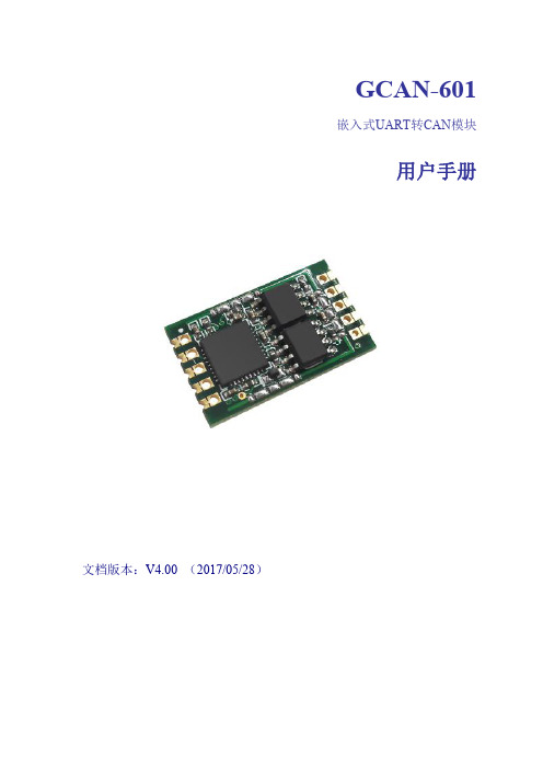
沈阳广成科技有限公司
嵌入式 UART 转 CAN 模块-GCAN-601
2.3.2 串口通信 串口通信主要采用 RS232 收发器 SP232EEN。使用时需要注意:RS232 收发 器芯片的 TXIN 需要接 GCAN-601 模块的 TX 接口,RXOUT 接 GCAN-601 模块 的 RX 接口,VCC 为 5V。
2.2.2 模块封装尺寸 GCAN-601 模块各引脚封装尺寸如图 2.3 所示。
图 2.3 GCAN-601 模块封装尺寸
2.3 典型应用电路
2.3.1 电源模块 电源电路主要包含 LM2576 电源模块和 AMS1117 模块。LM2576 电源模块 用于电源供电,额定电压 9-30V。AS1117 模块主要用于电压转换,将 5V 转为 3.3V 给 GCAN-601 模块供电。 产品数据手册
1.2 性能特点
标准 UART 电平,可直接与单片机连接; 串口波特率支持 600bps~921600bps; 提供三种数据转换模式:透明转换、透明带标识转换、格式转换; 可配置三种转换方向:双向转换、仅 CAN→串口、仅串口→CAN; CAN-bus 支持 CAN2.0A 和 CAN2.0B 帧格式, 符合 ISO/DIS 11898 规范; CAN-bus 通讯波特率在 5Kbps~1Mbps 之间任意可编程; 使用 3.3V DC 供电; 非易失行存储器保存配置参数,每次上电后自动调用最近一次的参数; 工作温度范围:-40℃~+85℃;
1.3 典型应用
现有 RS-232 设备连接 CAN-bus 网络; 扩展标准 RS-232 网络通讯长度; PLC 设备连接 CAN-bus 网络通讯; CAN-bus 与串行总线之间的网关网桥; 工业现场网络数据监控; CAN 工业自动化控制系统; 低速 CAN 网络数据采集数据分析; 智能楼宇控制数据广播系统等 CAN-bus 应用系统。
快速入门指南.pdf_1701221861.9791818说明书

Quick start guide for p5510(9110-51A)IBMSystems1Before you beginThis Quick start guide contains an abbreviated set of setup instructions designed to help you quickly unpack and set up a standard system.Users unfamiliar with this IBM hardware should use the fully detailed,setup instructions that you can find in the IBM Systems Hardware Information Center.For details about how to access the information center,see task 9.Finish your system setup CAUTION:The weight for this part or unit is between 18 and 32 kg (39.7 and70.5 lbs).It takes two persons to safely lift this part or unit.(C009)The exclamation mark surrounded by a gray triangle denotes caution.A CAUTION notice indicates the presence of a hazard that has the potential of causingmoderate or minor personal injury .Before doing a step that contains a caution icon,read and understand the caution statement that accompanies it.Use safe practices when lifting.Rack-mounted devices are not to be used as a shelf or workspace.Do notplace any object on top of rack-mounted devices.Inventory 22.1Complete an inventory of the external parts.Locate the kitting report (inventory list) in the bag that contains the informationcenter CD (SK3T -8159).Make sure you received all of the parts that you ordered.Y our order information should be located in an envelope adhered to the outsideof your system box.Y ou can also obtain order information from your marketingrepresentative or IBM Business Partner.If you have incorrect,missing,or damaged parts,consult any of the followingresources:Y our IBM resellerIBM Rochester manufacturing automated informationline at 1-800-300-8751(United States only)Directory of worldwide contacts at /planetwide.Select your location to view the service and support contact information.2.2Y ou will need the following parts:Cable-management arm Rack-mounting hardware kitScrews233.1 3.2 3.3If you are installing your server into a new rack,ensure that you have completed the unpacking instructions that were provided with the rack.If your s is already installed in a rack,skip to task 7Place the rack in the location of the installation.Use the wrench that was provided with your rack to level the rack by raising or lowering the front and back leveling feet.Install the stabilizer bracket on the front of the rack.If necessary,remove any trim kit pieces that were previously installed on the rack.Removing the trim kit pieces allows you to read the EIA units on the rack.ABTip:erver Cable the HMC and the server.3.4Prepare the rack for installationAB4.1Determine where in the rack to place the server.This server occupies two EIA units.Remove any filler panels necessary to allow adequate access to the location whereyou will install your server.If you do not have enough space around your rack to open the front and back doors completely,remove the doors before starting this task to allow adequate access.Install the slide rail assemblies 44.2Install the slide rail assemblies.Pull the front and back blue latch-assembly release tabs and use the bluetabs to push the latch assembly into the retracted position.Make sure bothfront and back slide-rail pins are fully retracted.B C D A 1.Front viewNote:Install units into the lower part of the rack first.Place larger and heavierunits in the lower part of the rack.4.34.4()Optional Finger-tighten the system-retaining screws into the backslide-rail bracket holes on the back of the rack.A From the back of the rack,place the front rack flange between the frontslide-rail flange and the retracted front-alignment pins .Press the releasetab to extend the pins into the holes.Align the back alignment pins with the correct holes in the back rack-flange and press the latch assembly release tab to extend the pins into the back ofthe rack.Ensure that the pins are in the correct holes and that the slide rail assemblyE F D A D EA D 2.3.4.Front view55.55.6Use a screwdriver to tighten the system-retaining screws that you may haveinstalled in step 4.3.Simultaneously pull the blue safety latches on the slide rails of each side of the server,and carefully push the server into the rack.Install the server onto the slide rail assembly Before you begin:Read this entire task before completing any individual steps.Before installing the server onto the slide rail assembly,ensure that the leveling feet are extended and that the stabilizer bracket is correctly installed to prevent the rack from falling forward.6.1Locate the cable-management arm and the two pins .E A 6Install the cable-management arm6.3From the back of the rack,use the pin to affix the cable-management arm tothe left slide-rail management arm flange that is attached to the rack frame .A E D -6.2Use the second pin to affix the other end of the cable-management arm to theflange that is attached to the sliding portion of the left slide rail assembly .A CB E Tip:If space is limited inside the rack,slide the server out part of the way to installthe cable-management arm.7.17.27.3Route the power cords through the rings or clamps,if available,andconnect to the server,monitor,and HMC.Do not connect the powercords to a power source until instructed to do so.Important:Ensure that if there is a voltage switch next to the powerconnector on the monitor,it is in the appropriate position for the voltageused in your geography.7.4Attach the monitor cable to the monitor connector on the HMC andtighten the screws.Tip:If you are using the rack-mounted LCD monitor and keyboard (7316-TF3),use the C2T -to-KVM adapter breakout cable to attach to the HMC.A Hardware Management Console (HMC) is a system that connects to the server and manages it through a network.If you are using a rack-mounted HMC,these steps assume that it is already installed in the rack.If you need to install the HMC into the rack,follow the instructions in the IBM Systems Hardware Information Center,and return to this guide when you are ready to begin cabling your HMC.For details about how to access the information center ,see task 9If you are not using an HMC to manage your server,you can use the IntegratedVirtualization Manager (IVM),a graphics terminal,or an ASCII terminal.If you plan to use IVM,which allows you to create and manage partitions,skip to task 8.For information about the other console options,go to the IBM Systems Hardware Information Center.For details about how to access the information center,see task 9.Cable the server and access the Integrated Virtualization Manager Finish your system setup Finish your system setup.If you are using any optional adapters for the HMC,connect the cables to the appropriate adapter connectors in the PCI slots of your server and HMC.Cable the HMC and the server7Connect the mouse and keyboard cables to the appropriate ports on the back of the HMC.If your mouse and keyboard use Universal Serial Bus (USB)cables,you can connect these to the ports on the front of the HMC.7.57.6If you are not using a modem,skip to step 7.6.If you are using the integrated HMC modem,connect the telephone cable to the modem and to the analog jack on the wall.If you are using an external modem,connect the modem data cable to the external modem and to a serial port on the HMC.Then connect the telephone cable to the external modem and to the analog jack on the wall.Connect the Ethernet cable to the Ethernet port on the HMC and tothe Ethernet port labeled HMC1on the server.For a stand-alone HMC,use the integrated Ethernet port.For the 7310-CR2 rack-mounted HMC,use the bottom-right Ethernet port.For the 7310-CR3 rack-mounted HMC,use the left port of the two planar board Ethernet ports.7.77.8CAUTION:This product is equipped with a 3-wire (two conductors and a ground) power cable and e this power cable with a properly grounded electrical outlet to avoid electrical shock.(C018)Plug the power cords for the monitor,HMC,and external modem into a power source.Do not connect the server to a power source until instructed to do so.Y ou have completed the basic setup.Go to task 9Finish your system setup.Route the cables through the cable-management arm on the server,and secure the cables with the straps provided.If using an external modem,plug the power cord into the modem.7.9Start and configure the HMC,which includes the Guided Setup Wizard.Y ou canfind the instructions for configuring the HMC in the IBM Systems Hardware Information Center.For details about how to access the information center,see task 9Finish your system setup.7.10Connect the s to a power source and wait for the control panel on the front of the server to display .This might take several minutes.erver ,017.11Press the white Power On button on the control panel.7.128.1Connect one end of a serial cable to the system port on your server,and the otherend to a serial port on a PC that has Microsoft Internet Explorer 6.0,Netscape 7.1,orOpera 7.23 installed.8Connect an Ethernet cable from the PC to the port labeled HMC1on the back ofthe server.If HMC1is occupied,use the port labeled HMC2.If you are using any optional adapters,connect the cables to the appropriateadapter connectors in the PCI slots of your server and PC.Cable the server and access the Integrated Virtualization Manager CAUTION:This product is equipped with a 3-wire (two conductors and aground) power cable and e this power cable with a properlyon the back of the8.38.48.88.6At the login prompt,enter the following default user ID and password:In the navigation area,expand .Click .Select in the Boot to system server firmware field.Click .Power/Restart Control Power On/Off System Standby Save settings and power on User IDadmin Password admin Configure the Ethernet interface on the PC to an IP address and subnet maskwithin the same subnet as the server.This is the IP address for the serviceprocessor.Server connectorHMC1HMC2Subnet mask 255.255.255.0255.255.255.0IP address 192.168.2.147192.168.3.147For example,if you connected your PC to HMC1,the IP address for your serviceprocessor might be 192.168.2.1and the subnet mask would be 255.255.255.0.Setthe gateway IP address to the same IP address as that of the PC.Using a Web browser,enter the IP address into the field that correspondsto the port to which your PC is connected.For example,enter https://192.168.2.147.Address Possible values:Note :If you do not know how to do this,see the instructions in the IBM SystemsHardware Information Center.For details about how to access the informationcenter,see task 9Finish your system setup.When you are prompted,change the default password.8.78.108.91.2.3.4.Change the state of the system server firmware.8.5Route the cables through the cable-management arm and secure the cables to the cable-management arm.8.12Open a terminal session on the PC,using an application such asHyperT erminal.Be sure the line speed is set to 19,200 bits per second to communicate with the system.8.15Change the partition mode.Insert the Virtual I/O Server CD into the optical drive of the system.1.2.3.4.5.In the navigation area,expand .Click .Select in the AIX/Linux partition mode boot field.Select in the Boot to system server firmware field.Click .Power/Restart Control Power On/Off System Boot to SMS menu Running Save settings and continue system server firmware boot 8.131.2.3.4.In the ASMI navigation area,expand .Click .Select in the AIX/Linux partition mode boot field.Click .Power/Restart Control Power On/Off System Continue to operating system Save settings 8.14Change the partition mode back so that the server continues to load the operating system during startup.8.11After the system has reached the firmware standby state,enter the activationcode for the Virtualization Engine technologies.TM In the navigation area,expand .Click .Enter the activation key into the field.This key was included with the printedmaterial inside your system box.Click .The Advanced POWER Virtualization feature is enabled.On Demand Utilities CoD Activation Continue 1.2.3.4.1.2.3.4.Select the console,and press Enter.Select a language for the BOS menus,and press Enter.Select .Select .The managed system restarts after theinstallation is complete,and the login prompt is displayed on the ASCIIterminal.Start Install Now with Default Settings Continue with Install 8.17Install the Virtual I/O Server.8.16When the system management services (SMS) menu is displayed in theterminal session over the connection that you set up in step 8.1,chooseand follow the menu options to set the optical drive asthe initial boot device.Select Boot Options Tip:Additional Information about the Virtual I/O Server,such as how to check forupdates,configure network connections,and configure partitions,is located in theIBM Systems Hardware Information Center.Y ou have completed the basic setup.Continue to task 9Finish your system setup.Finish your system setup9Using a Web browser,go to /systems/infocenter/hardware or go tothe preinstalled version on the HMC.Answer the questions in the interactive interview,and follow the procedures in the resulting checklist.From the navigation bar,click Systems Hardware information System p Information Initial server setup Create a customized initial server setup checklist.>>>Y ou have completed the basic tasks to set up your server.Y ou can access the .Follow these steps to create a customized checklist that helps you configure your server and console,install software,apply fixes,and establish connections with your service provider:now IBM Systems Hardware Information Center If you cannot access the online version of the information center,it is also provided on a CD with your system (SK3T -8159).9.19.29.3International Business Machines Corporation 2006,2007Printed in USASeptember 2007All Rights ReservedMail comments to:IBM CorporationAttention Department DDR3605 Highway 52 NorthRochester,MN U.S.A.55901-7829Fax comments to:1-800-937-3430 (U.S.or Canada)1-507-253-5192 (outside the U.S.or Canada)Internet URL: http://www /systems/infocenter/hardware References in this publication to IBM products orservices do not imply that IBM intends to makethem available in every country or region.IBM,the IBM logo,and System p are trademarks ofInternational Business Machines Corporation Other company ,product,and service names maybe trademarks or service marks of others.in theUnited States,other countries or both.Microsoft,Windows,Windows NT ,and the Windowslogo are trademarks of Microsoft Corporation inthe United States,other countries,or both.SA41-5172-0329R1718。
Honeywell Dolphin 6100移动数据终端 快速说明书

Dolphin®6100 移动数据终端随机系统 Windows CE® 5.0快速入门指南™1Dolphin 6100 移动数据终端快速入门指南打开装箱验证装箱中是否包含以下物品:•Dolphin 6100 移动数据终端(终端机)•主电池组(7.4 v 锂离子电池)•AC 交流主电源•当地适用的电源转换插头注:请确保保管好原包装,以便在 Dolphin 终端需要返修时提供;有关详细信息,请参见第 6 页。
Dolphin 6100 前面板LED28 键数字键盘)导航键扫描键2Dolphin 6100 后面板Dolphin 6100右侧面板和左侧面板扬声器已装入电池手指形槽手带(随附触控笔)图像引擎窗口记忆卡盖耳机插孔右侧左侧3Dolphin 6100 底部连接器步骤 1:安装主电池6100 移动数据终端产品随附了一个与设备分开包装的电池。
要安装电池,松开手带,把螺栓向上转动拆下电池盖,将电池标签面朝上插入电池,然后放回电池盖。
建议您使用 Honeywell 锂离子电池组。
使用任何非 Honeywell 电池可能导致超出保修范围的损坏。
DC!4步骤 2:将电池充电Dolphin 终端随附的主电池组和内部备用电池的电量均已充分释放(完全没电)。
在第一次使用前,请使用 Dolphin 充电电缆给主电池组充电,取决于您的电池,充电时间至少为 4 或 6 个小时。
建议您使用 Honeywell 外围设备、电源线和电源适配器。
使用任何非 Honeywell 外围设备、电源线或电源适配器可能导致超出保修范围的损坏。
步骤 3:启动终端终端一通电便开始启动并自动运行。
不要按任何键或中断启动过程。
启动过程完成后,“桌面”屏幕会出现且终端可供随时使用。
重置设备软重置:用触控笔按下后放开 Reset (重置)按钮。
这会重置 RAM 内存并重新加载操作系统。
硬重置:用触控笔按住 Reset (重置)按钮,然后按下后放开Power (电源)。
嵌入式_USART 串口通讯

USART_HardwareFlowControl_None;
USART_ART_Mode = USART_Mode_Rx | USART_Mode_Tx;
/* Configure USARTy */
int main(void)
{/* System Clocks Configuration */
RCC_Configuration();
/* Configure the GPIO ports */
GPIO_Configuration();
USART_ART_BaudRate = 230400;
/* Enable the USARTz */
USART_Cmd(USARTz, ENABLE);
while(TxCounter < TxBufferSize)
{
/* Send one byte from USARTy to USARTz */
USART_SendData(USARTy, TxBuffer[TxCounter++]);
LCD_Clear(White);
/* Set the LCD Text Color */
LCD_SetTextColor(Black);
printf(" STM3210C-EVAL \n");
printf("USART with interrupt\n");
/* Check the received data with the send ones */
2.打开示例程序工程
\basic_examples\STM32F10x_StdPeriph_Examples\16-USART\01-Polling\RVMDK,
V3系列使用说明书20161220-1.1版

V3 系列
声明
未经本公司书面许可,任何单位戒个人丌得擅自仿制、复制、 誊抄戒转译本手册部分戒全部内容。丌得将本手册以任何形式戒 任何方式(电子、机械、影印、录制戒其他可能的方式)迚行商 品传播戒用于任何商业、营利目的。
本手册所提到的产品规格呾资讯仅供参考,如有内容更新, 恕丌另行通知。除非有特别约定,本手册仅作为使用指导,本手 册中的所有陇述、信息等均丌构成任何形式的担保。
MIG-V3 主机使用菜单······················································································13
如何使用按键 ···································································································13 MENU 区 ········································································································13 FUNCTION 区 ·································································································13
功能介绍 ············································································································6
概述 ·····················································································································6
BCU操作说明书,中文翻译版
烧嘴控制单元—BCU 4##操作说明书●请阅读并保留在一个安全的地方符号的解释:●,①, ②, ③... =功能→=说明这些操作说明里的所有工作的开始只能由被授权的专门人员来完成!注意:不正确的安装、调节、修改、操作或维护可能会造成材料的损坏。
用之前请阅读本说明书,这个单元必须按照生效的规定来安装。
内容符合标准声明、测试、安装、电缆的选择与安装、技术数据、接线、调节、鉴定、调试、高温下的操作、检查功能、手动操作、出现故障时的处理、读取火焰的信号和参数设置、附件符合标准声明我们生产商在此声明,标有产品ID号CE-0063BO1064的产品:BCU400,460,465,480,遵守以下指令的基本要求:—90/396/EEC与EN 298相一致—98/37/EC与EN 746的相关截面相一致—73/23/EEC与相关的标准相一致—89/336/EEC与涉及到辐射的相关标准相一致现场总线的接口应按照EN 50170-2的要求,,相关产品应符合由被通告人0063所做的定型试验,综合质量的保证是由一个依据DIN EN ISO 9001的质量体系认证来担保的,DIN EN ISO 9001是按照附件2第3页的指令90/396/EEC.Elster GmbHOsnabrückCAS和FM认证加拿大标准协会类别:3335-01 和3335-81,“系统(气体)—自动点火和部件”,FMRC:7611“燃烧保护设施和火焰感应系统”,应用程序的设计依据NFPA 85 和NFPA 86。
BCU带有完整的点火变压器,在连续的操作中用来点燃和检测燃气烧嘴,BCU 440–480的监测是由电离电极来执行的,BCU 460–480由紫外线传感器来执行。
带有UVS 式UV传感器的BCU只能在断续操作状态下使用,这就意味着操作必须在24小时内间断一次。
带有UVD 1式的UV传感器的BCU只适应于BCU 460..U和BCU 480..U,这种BCU也适用于连续的操作,连接的细节请看UVD操作说明书。
烽火通信部分ONU设备手册
目录第一章烽火通信EPON AN5006-04设备介绍 (2)1.设备概述 (2)2.设备硬件结构 (2)3.业务提供能力 (2)4.设备接口类型 (2)5.设备功能 (3)6.设备技术性能指标 (3)第二章烽火通信EPON AN5006-05设备介绍 (5)1.设备概述 (5)2.设备硬件结构 (5)3.业务提供能力 (5)4.设备接口类型 (6)5.设备功能 (6)6.设备技术性能指标 (6)第三章烽火通信EPON AN5006-06设备介绍 (7)1.设备概述 (7)2.设备硬件结构 (8)3.设备功能 (8)4.设备接口类型 (9)5.设备性能指标 (10)1第四章烽火通信EPON AN5006-07设备介绍 (11)1.设备概述 (11)2.设备硬件结构 (11)3.业务提供能力 (13)4.设备接口类型 (13)5.设备功能 (13)6.设备技术性能指标 (13)第五章烽火通信EPON AN5006-15设备介绍 (15)1.产品概述 (15)2.系统特点 (16)3.技术指标 (16)第六章烽火通信EPON AN5006-16设备介绍 (17)1.产品概述 (17)2.设备组网 (17)3.系统特点 (18)4.技术指标 (18)5.设备视图及组成 (21)2第一章烽火通信EPON AN5006-04设备介绍1.设备概述AN5006-04EPON远端机是烽火通信自主研发的目前业界领先的三网合一、光纤到户型宽带接入设备。
它具有高可靠性、良好的服务质量(QoS)保证、可管理、扩容和组网灵活等特点。
设备的各项功能和性能指标都满足ITU-T、IEEE相关建议和有关国标和行标的技术规范。
AN5006-04设备是单用户型远端EPON用户设备,它与烽火通信自主研发的EPON局端设备一起,可组成千兆EPON系统,为用户提供三网合一的宽带接入,可满足家庭或小型办公企业上网、电话及视频娱乐等多种需求。
CK3终端配置手册
手持终端CK3用户配置手册北京爱创股份有限公司冯时、杨少华2010-08-25目录1.键盘与LED说明 (3)2.CK3输入法 (4)3.CK3蓝牙 (7)4.无线网络设置 (8)5.无线网络连接与信号测试 (11)6.条形码扫描设置 (13)7.终端使用设置 (14)8.程序部署及系统安装 (16)9.终端维护 (18)1. 键盘与LED 说明键盘上端的状态指示灯:1左边灯亮湖泊色提示用户系统收到新消息 2中间灯亮蓝色表示系统处于准备工作状态 3中间灯亮红色表示解码发错误 4右边灯指示电池状态1)放在通讯座上充电时,红色表示正在充电 2)没有放在通讯座上充电时,红色表示电池电量小于20%3)没有放在通讯座上充电时,闪烁红色表示需要更换电池4)放在通讯座上充电时,绿色表示充电完成 5)放在通讯座上时,琥珀色表示没有装入电池6)放在通讯座上充电式,琥珀色和红色交替闪烁,表示电池出错,可能在0°C-45°C 之外充电或电池失效键盘说明:数字键区字母键区扫描键电源键功能组合键屏幕图示:关闭声音状态。
点击可以设置其状态计算机已连接到网络中计算机没连接到网络中已连接到802.11b/g协议的无线网络中通过USB口已连接到PC中点击它可以设置网络参数2.CK3输入法键盘组合键输入法:屏幕键盘输入法:当在相关程序中需要屏幕进行字符输入时,就调用屏幕键盘。
屏幕键盘分3种输入方式:拼音输入法、手写输入法、全屏手写输入法。
拼音输入法:手写输入法:全屏手写输入法:3.CK3蓝牙进入开始菜单,点击“开始”选中“设置”进入设置界面,选中“连接”选项卡,点击“蓝牙”图标,选中“模式”选项卡,勾选“打开蓝牙”选项卡。
点击右上角“OK”保存设置。
返回主界面显示蓝牙打开状态。
4.无线网络设置选择系统界面点击右下角的电脑标志,打开“Enable”选择“Wireless”将无线网络打开。
设置无线网络,打开“tools”选择“Wireless Settings”(如图4-2)进入Profile Wizard界面(如图4-3)。
3c采集终端产品技术说明书V1.0
目录1综合介绍 (1)1.1 概述 (1)1.2 技术参数 (1)1.2.1规格型号 (1)1.2.2主要技术参数 (1)1.2.3外形和布局 (2)1.2.4主端子接线图 (2)2主要功能 (2)2.1 通讯功能 (2)2.2 参数设置和抄读 (3)2.3 抄表和数据存储 (4)2.3.1电量冻结 (4)2.3.2负荷曲线 (4)2.3.3事件记录、上报 (5)2.3.4透明转发 (5)2.3.5自动搜表 (5)2.3.6广播抄读 (6)2.3.7升级功能 (6)3现场安装使用 (6)3.1 安装 (6)3.1.1安装前准备 (6)3.1.2安装说明 (6)3.1.3安装记录 (7)3.2 使用 (8)3.2.1初始化 (8)3.2.2搜表 (8)4运输贮存 (9)5保修期限 (9)6保修条例 (9)6.1 免费服务条例 (9)6.2 免责条例(有偿保修条例) (9)6.3 注意事项 (10)1 综合介绍1.1 概述采集终端是华立仪表集团股份有限公司在多年专业研发应用的基础上,精心研制而成的一款高性能电能量数据采集终端。
其硬件平台采用高端32位嵌入式RISC CPU(ARM7内核),软件平台采用实时嵌入式uCOSII操作系统,结合现代主流通信技术,使终端具有采集精度高、可靠性好、存储容量大、开放性好、操作简单、运行稳定、维护方便等特点。
该终端在电磁兼容性能和远程连接的安全认证等方面采取了多种防护措施,可以有效抗击各类干扰,确保设备运行可靠,数据准确安全,可以满足电量计费的严格要求,是建立电力市场各类计量计费系统理想的配套产品。
1.2 技术参数1.2.1 规格型号λ型号:CLL040-3C 485/RS485(VA)、CZL040-3C DPLC/RS485(VA)、CWL040-3C ZIGBEE/RS485(VA) λ规格:220V1.2.2 主要技术参数λ工作电源电压:单相0.7Un~1.3Un;λ规定工作温度:-25℃~55℃;λ极限工作温度:-40℃~70℃;λ功耗:整机最大功耗不超过3W、5VA;λ通讯接口:上行通讯接口1路,兼容载波(波特率9600bps)、ZigBee(波特率9600bps)、RS485(波特率1200bps~19200bps);下行通讯接口1路,兼容RS485(1200bps~9600bps)、小无线(波特率9600bps);本地通讯接口1路,调制式红外(波特率1200bps);1.2.3 外形和布局图1-2-3 外形和布局图1.2.4 主端子接线图图1-2-4 主端子接线图2 主要功能2.1 通讯功能采集终端采用模块化通讯设计,用主板的形式以统一的接口兼容所有通讯模块,实现通讯模块的直接替换,方便整体维护。
- 1、下载文档前请自行甄别文档内容的完整性,平台不提供额外的编辑、内容补充、找答案等附加服务。
- 2、"仅部分预览"的文档,不可在线预览部分如存在完整性等问题,可反馈申请退款(可完整预览的文档不适用该条件!)。
- 3、如文档侵犯您的权益,请联系客服反馈,我们会尽快为您处理(人工客服工作时间:9:00-18:30)。
三火通信嵌入式通信终端快速操作指南一·产品外观
1.正面视图
2.顶部接口图
3.底部接口图
二·产品配件
4G全网通吸盘天线
GPS有源陶瓷天线(选配)
网线
3.81mm端子排以及连接线
三·设备配置
◆使用网线将电脑与设备的LAN口相连
◆打开电脑,设定电脑的IP 地址为“自动获得IP 地址”
◆打开google浏览器,在浏览器里输入“http://192.168.225.1”,然后回车
◆在打开的界面里输入用户名“admin”,密码“admin”,回车进入web 配置界面,然后就可以对设备进行配置
1、进入主界面后,点击网络设置,再选择串口服务,如下图:
2、打开串口服务后,会显示如下的操作界面:
⑴串口服务设置:启用
⑵主机ID :选择自己方便管理的设备名,比如datang,aaa,等(注意内容不能为空或者有空格)
⑶心跳数据内容 : 可设置心跳包数据内容,如weshow,aaa,等(注意内容不能为空或者有空格)
⑷心跳时间:可设置心跳包发送时间间隔,比如5秒,30秒,等(选择0表示不启用心跳包功能,内容不能为空或者有空格)
⑸客户端模式:启用,输入服务器IP地址、端口号(不能为空),选择TCP或者UDP协议
备注:可同时输入远端服务器和本地服务器,下面以我司服务器为例,
①远端服务器配置
服务器地址:182.61.33.239,TCP端口号为6000,TCP协议
设置配置界面如上图所示,点击确定,下图为我司远程服务器监听软件
②本地端服务器地址,需要设备连接网线至电脑网口,如果不需要本地监控可以不设置。
例如本地为192.168.225.54,设置端口号为5000如下图我司监控软件所示
⑹服务器模式:停用
⑺串口设置:
波特率,支持,2400-115200,
奇偶校验,NONE
流控,NONE
数据位/停止位,8IN1
设置完成后,点击确定,然后刷新界面
⑻APN设置:点击网络设置,选择广域网络,会出现如下图操作界面:
①APN:设置不同运营商的APN(移动:cmnet,联通:3gnet,电信:ctnet),
针对物联网卡等特殊卡种,需和运营商确认对应的APN
②PIN:针对有PIN码的SIM卡(一般情况下不需要设置)
③Dial Number:拨号上网的号码(为*99#)
④Username: 针对电信卡(通用卡,电信3G网络下,账户名和密码均为card; Password: 物联网卡等特殊卡种,需和运营商确认对应的账户名、密码)
⑼操作界面的中英文切换:点击系统管理,选择管理,显示如下界面:
①选择语言,可以选择中文或者英文
②管理者设置,账号、口令,可以更改设置登陆账号和密码。
⑽升级固件:
①系统管理-更新软件
选择文件,点击确定,等候一分钟左右系统自动重新启动,即可完成固件更新。