SATEC PM175
A-T Controls 31 Series 3-Way Flanged Direct Mount

31Series-2R-20230502Copyright 2013 A-T Controls, Inc.PneumaticElectricSee automated data sheets for pre-sized assembliesEasy to Automate!This 3-way ball valve offers diverting and mixing flow patterns, often eliminating the need for two valves. The full port design is easily automated and isavailable with various seat materials. The bolts on side flanges make for easy seat changes as necessary to accomodate your service. Available in L or T port configurations.Cincinnati, Ohio FAX (513) 247-5462********************3-Way 150# Flanged Direct Mount Ball ValveShaded boxes indicate standard flow path from factory unless otherwise specified by customer. Automated assemblies rotate counter-clockwise standard from the factory when energized. For L-Ports that would be L1 to L2 and T3 to T4 for T-ports. By specifying FCCW or DAR actuators, multiple flow patterns can be achieved to meet process requirements.FLOW PATTERNSCRN3-Way Flanged Ball Valve Full Port, L or T Option ANSI Class 150TFM™ is a trademark of Dyneon™, a 3M Company.Kalrez is a registered trademark of DuPont Performance Elastomers.# 1-1/2” THRU 3” = Qty. 12 pcs | 4” = Qty. 18 pcs | 6” = Qty. 30 pcs^ 1-1/2” THRU 3” = 4 pcs, 4” = 6 pcs., 6” = 12 pcsDIMENSIONS For ANSI Class 150 (IN)NOTE: At temperature, valves are limited by either the valve body/end cap pressure ratings, seat pressure ratings, or packing/stem seal/gaskets;whichever is lower.Published torquesare based on full differential pressure with clean water. Consult the Application Sizing Guide for assistance with sizing actuators.Cincinnati, Ohio FAX (513) 247-5462********************Actuators are sized based on clean/clear fluid.SERIES 31 3-Way 150# Flanged Direct MountFlanged 3-WayClass 150 Double Acting Assembly For operating temperatures in excess of 175° F with Buna-N seals in the actuator, an extended bracket is required. FKM seals in the actuator require an extended bracket for more than 300° F. Please consult factory for sizing information.Actuators are sized for clean liquid surface with a specific gravity of 1 and at 70° F.SAMPLE PART #31C-FX-150/2R3D-_ _ _(2) Valve Series (4) End Connection (6) Valve Size(5) Seat, Lining, & TrimMaterial(7) Actuator(8) Accessories/Options(3) Body/Ball/StemMaterial(9) Accessories(10) Special Designation Refer to Series 31 IOM for all repair kit, seat and gasket part numbers.See the last page of catalog for How To Order detail and options.See Automated Part Number Matrix for complete part number and options.31Series-2R-20230502Copyright 2013 A-T Controls, Inc.Flanged 3-WaySERIES 313-Way 150# Flanged Direct MountCincinnati, Ohio FAX (513) 247-5462********************Class 150 Spring Return AssemblySpecify flow pattern when ordering. See automated part number matrix for complete part number and options.Note: A number following the actuator model (Ex: 2R6S4), indicates the number of springs per side. For a standard (5 spring per side) actuator, the spring designation is omitted from the automated part number.Actuators are sized for clean liquid surface with a specific gravity of 1 and at 70° F.For operating temperatures in excess of 175° F with Buna-N seals in the actuator, an extended bracket is required. FKM seals in the actuator require an extended bracket for more than 300° F. Please consult factory for sizing information.SAMPLE PART #31C-FX-150/2R6S4-_ _ _(2) Valve Series (4) End Connection (6) Valve Size(5) Seat, Lining, & TrimMaterial(7) Actuator(8) Accessories/Options(3) Body/Ball/StemMaterial(9) Accessories(10) Special Designation Refer to Series 31 IOM for all repair kit, seat and gasket part numbers.See the last page of catalog for How To Order detail and options.See Automated Part Number Matrix for complete part number and options.31Series-2R-20230502Copyright 2013 A-T Controls, Inc.Flanged 3-WayCincinnati, Ohio 45246 FAX (513) 247-5462********************NOTE: Heater and thermostat standard (2) auxiliary switches standardOther options available - call for detailsActuators are sized based on clean/clear fluid.SERIES 31 3-Way 150# Flanged Direct MountClass 150 Electric Assembly Actuators are sized for clean liquid surface with a specific gravity of 1 and at 70° F.For operating temperatures in excess of 158° F with an electric actuator, an extended bracket is required. Please consult factory for sizing information.SAMPLE PART #31C-FX-150/WEC1-_ _ _(2) Valve Series (4) End Connection (6) Valve Size(5) Seat, Lining, & TrimMaterial(7) Actuator(8) Accessories/Options(3) Body/Ball/StemMaterial(9) Accessories(10) Special Designation Refer to Series 31 IOM for all repair kit, seat and gasket part numbers.See the last page of catalog for How To Order detail and options.See Automated Part Number Matrix for complete part number and options.31Series-2R-20230502Copyright 2013 A-T Controls, Inc.17-4 PH ® is a registered trademark of AK Steel Corporation.Chemraz® is a registered trademark of Greene, Tweed & Co.Markez® is a registered trademark of Marco Rubber & Plastic Products Inc.Perlast® is a registered trademark of Precision Polymer Engineering Limited.TFM TM is a trademark of Dyneon TM, a 3M Company.HOW TO ORDER: Manual ValvesSAMPLE PART #31C-F1-0200-XXX-_ _ _(2) Valve Series (4) End Connection(5) Valve Size(6) Seat, Lining, & TrimMaterial(7) Special Designation (8) Additional Specials(9) Special Designation(3) Body/Ball/StemMaterial(10) O-RingDesignation (11) AdditionalSpecialsRefer to Series 31 IOM for all repair kit, seat and gasket part numbers.31Series-2R-20230502Copyright 2013 A-T Controls, Inc.SAMPLE PART #31C-FX-200/2R3D-_ _ _(2) Valve Series (4) End Connection (6) Valve Size(5) Seat, Lining, & TrimMaterial(7) Actuator(8) Accessories/Options(3) Body/Ball/StemMaterial(9) Accessories(10) Special Designation Refer to Series 31 IOM for all repair kit, seat and gasket part numbers.HOW TO ORDER: Automated ValvesCincinnati, Ohio FAX (513) 247-5462********************31Series-2R-20230502Copyright 2013 A-T Controls, Inc.。
维萨拉工业测量产品手册说明书

维萨拉工业测量产品手册湿度 | 温度 | 露点 | 二氧化碳 | 沼气 | 油中水分 | 连续监测系统 |溶解气体分析系统 | 过氧化氢 | 压力 | 气象 | 服务支持观测让世界更美好维萨拉的工业测量业务领域产品能够帮助客户了解工艺过程。
我们的产品为客户提供准确可靠的测量数据,帮助客户做出优化工业过程的决策,从而提高过程效率、产品质量、生产力和产量,同时减少能源消耗、浪费和排放。
我们的监测系统还能帮助客户在受监管的环境中运营,以履行监管合规性。
维萨拉工业测量服务于多种类型的运营环境,从半导体工厂和高层建筑,到发电厂和生命科学实验室,对环境条件的可靠监测是实现成功运营的先决条件。
维萨拉的测量产品和系统广泛应用于监测温度、湿度、露点、气压、二氧化碳、汽化过氧化氢、甲烷、油中水、变压器油中溶解气体和液体浓度等参数。
我们的生命周期服务可在测量仪表的整个使用寿命内提供维护。
作为值得信赖的合作伙伴,我们通过在产品和系统生命周期中保证准确的测量数据来支持客户做出可持续的决策。
本产品目录对我们的产品进行整体的介绍,以帮助您选择适合您需求的产品。
如需更多信息,请通过以下方式联系我们:销售热线:400 810 0126电子邮箱:**********************公司网址:扫描二维码,关注维萨拉企业微信3目 录Indigo系列变送器Indigo200系列数据处理单元 (7)Indigo300数据处理单元 (9)Indigo510数据处理单元 (12)Indigo520数据处理单元 (15)用于抽检和校准的手持设备Indigo80手持式显示表头 (18)HMP80系列手持式湿度和温度探头 (21)DMP80系列手持式露点和温度探头 (23)HM70手持式湿度和温度仪 (26)HUMICAP® 手持式湿度温度仪表HM40系列 (29)DM70手持式露点仪 (33)MM70适用于现场检测的手持式油中微量水分和温度测试仪 (36)湿度和温度用于测量相对湿度的维萨拉HUMICAP® 传感器 (38)如何为高湿度应用选择合适的湿度仪表 (40)Insight PC机软件 (44)HMP1墙面式温湿度探头 (46)HMP3一般用途湿度和温度探头 (48)HMP4相对湿度和温度探头 (51)HMP5相对湿度和温度探头 (54)HMP7相对湿度和温度探头 (57)HMP8相对湿度和温度探头 (60)HMP9紧凑型湿度和温度探头 (63)TMP1温度探头 (66)适用于苛刻环境中湿度测量的HMT330系列温湿度变送器 (68)HMT370EX系列本安型温湿度变送器 (78)HMT310温湿度变送器 (84)HUMICAP® 温湿度变送器HMT120和HMT130 (87)适用于高性能暖通空调应用的HMW90系列湿度与温度变送器 (90)HMD60系列湿度和温度变送器 (92)HMD110/112和HMW110/112湿度和温度变送器 (96)适用于楼宇自动化高精度室外测量的HMS110系列温湿度变送器 (99)HMDW80系列温湿度变送器 (101)适用于楼宇自动化应用室外测量的HMS80系列温湿度变送器 (105)HMM100湿度模块 (107)适用于OEM应用的HMM105数字湿度模块 (109)HMM170温湿度模块 (111)INTERCAP® 温湿度探头HMP60 (113)4INTERCAP® 温湿度探头HMP63 (115)HUMICAP® 温湿度探头HMP110 (117)HUMICAP® 温湿度探头HMP113 (120)SHM40结构湿度测量套件 (122)HMK15湿度校准仪 (125)DTR500太阳辐射和雨水防护罩 (127)HMT330MIK气象安装套件 (129)适用于动力汽轮机进气测量的HMT300TMK汽轮机安装组件 (131)露点Vaisala DRYCAP® 传感器用于测量干燥过程中的湿度 (133)DMP5露点和温度探头 (135)DMP6露点探头 (138)DMP7露点和温度探头 (140)DMP8露点和温度探头 (142)DMT340系列露点和温度变送器 (145)适用于高温应用的DMT345和DMT346露点变送器 (151)DMT152露点变送器 (155)DMT143露点变送器 (157)DMT143L露点变送器 (160)用于冷冻干燥机的DMT132露点变送器 (162)DM70用DSS70A便携式采样系统和采样室 (164)DPT146露点和气压变送器 (166)DPT145多参数变送器 (168)二氧化碳适用于苛刻环境的维萨拉CARBOCAP® 测量传感器 (171)GMP343二氧化碳探头 (173)适用于CO2恒温箱的GMP231二氧化碳探头 (176)GMP251二氧化碳探头 (178)GMP252二氧化碳探头 (181)GM70手持式二氧化碳测试仪 (184)适用于苛刻通风要求应用的GMW90系列二氧化碳及温湿度变送器 (187)适用于智能控制通风系统 (DCV) 的GMW80系列二氧化碳、湿度和温度一体变送器 (190)按需控制通风系统中的GMD20系列二氧化碳变送器 (193)GMD110管道安装式二氧化碳变送器 (195)沼气MGP261多气体探头 (197)MGP262多气体探头 (199)油中水用于测量油中微水的维萨拉HUMICAP® 传感器 (201)MMP8油中水分探头 (203)MMT330系列油中微量水分与温度变送器 (205)5MMT310系列油中微量水分与温度变送器 (209)MMT162油中微量水分和温度变送器 (211)连续监测系统维萨拉viewLinc企业版服务器版本5.1 (213)AP10 VaiNet无线接入点 (215)用于连续监测系统的RFL100无线数据记录仪 (218)HMP115温湿度探头 (223)TMP115宽范围温度探头 (225)维萨拉温度与相对湿度数据记录仪系列DL2000 (227)维萨拉通用输入数据记录仪系列DL4000 (229)维萨拉多应用温度数据记录仪DL1016/1416 (231)维萨拉热电偶数据记录仪系列DL1700 (233)维萨拉中端温度、湿度及触点通道数据记录仪 (235)维萨拉vNet以太网供电数据记录仪接口 (238)溶解气体分析OPT100 Optimus™ 溶解气体分析(DGA)监测系统 (240)MHT410变压器油中微量水分、氢气和温度分析仪 (244)过氧化氢用于测量汽化过氧化氢、相对饱和度和相对湿度的维萨拉PEROXCAP® 传感器 (246)用于过氧化氢、湿度和温度测量的HPP270系列探头 (249)压力用于测量压力的维萨拉BAROCAP® 传感器 (253)PTU300气压、湿度和温度一体变送器 (255)适用于专业气象、航空与工业用户的PTB330数字式气压计 (260)气压传递标准PTB330TS (262)PTB210数字气压计 (265)PTB110气压计 (267)将风引起误差降低的SPH10/20静压头 (269)气象Vaisala用于工业应用测量的风和气象传感器技术 (271)风测量装置WA15 (273)WINDCAP® 超声波风传感器WMT700系列 (276)气象变送器WXT530系列 (278)服务支持面向仪表全生命周期服务 (280)67功能•数据处理单元 USB-C 端口支持使用通用 USB 电缆连接到维萨拉Insight PC 软件•数字和图形彩色显示屏(针对模拟型号提供可选的不带显示屏的款式)•IP65 外壳•24 V AC/DC 电源输入•Indigo201:3 个模拟输出(mA 或 V)•Indigo202:RS-485,带有Modbus ® RTU•2 个可配置的继电器维萨拉 Indigo200 系列数据处理单元是一种主机设备,它显示来自维萨拉 Indigo 兼容探头的测量值,同时也可通过模拟信号、Modbus RTU 通信或继电器将这些测量值传输到自动化系统。
Atmel AT30TK175数字温度传感器评估套件用户指南说明书

Atmel Digital Temperature Sensors Evaluation KitAtmel AT30TK175 Starter KitHardware User GuideFeatures•Four digital temperature sensor devices: •Atmel® AT30TSE002B•Atmel AT30TS75•Atmel AT30TS750•Atmel AT30TSE758•Four event LEDs•Four alarm status LEDs:•Critical, high, low, and normal•Software switchable V CC: 3.3V, 5.0V, and OFF •Power LED Contents•One Atmel AT30TK175 adapter board•One Atmel AT88Microbase AVR® base module •6-inch USB cable•18-inch extension cableIntroductionThis starter kit utilizes the Atmel AT30TK175 adapter board to allow users to experiment and develop with the AtmelAT30TSE002B, AT30TS75, AT30TS750, and AT30TSE758 digital temperature sensors.The AT30TK175 daughterboard interfaces with the Atmel AT88Microbase board (included in the kit) to provide communication to a PC via a USB interface, allowing designers to learn and experiment with the temperature sensor demonstration utility. In addition, this kit supports a modular approach, enabling the AT30TK175 daughterboard to connect directly to an Atmel STK® series AVR development platform to easily add temperature monitoring capabilities to applications.Figure 1.Atmel AT30TK175 adapter boardAlarm status LEDs1.Atmel AT30TK175STK Starter KitThe AT30TK175 is sold with the AT88Microbase to form the Atmel AT30TK175STK starter kit. For additional information on the AT88Microbase, see the “Atmel AT88Microbase Hardware User Guide.”The Atmel AT30TK175 daughterboard with the Atmel AT88Microbase moduleFigure 1-1.2.Board ConfigurationTable 2-1. Seven-bit device address2.2.10-pin Interface HeaderTable 2-1.I2C pins: SCL, SD2 Atmel AT30TK175 Starter Kit Hardware User GuideFigure 2-2.10-pin interface header orientationNote:VCC_SEL and VCC_EN are board-level options that allow users to set the board V CC to 3.3V or 5.0V and disable V CC with VCC_EN. These options are provided to allow the temperature sensor to be evaluated withboth V CC operating voltages and to evaluate the nonvolatile registers (see Section 2.3).2.3.Alarm Status LEDsTable 2-1.Alarm status LEDs2.4.V CC Enable and Select PinsTable 2-1.V CC enable and select pinsControl High Low StateVCC_EN X ON (Default)VCC_EN X OFFVCC_SEL X 3.3V (Default)VCC_SEL X 5.0VAtmel AT30TK175 Starter Kit Hardware User Guide 33.References and Further InformationSchematics, Gerber files, bill of materials (BOM), and development and demonstration software are conveniently downloadable from the Atmel website.4.EVALUATION BOARD/KIT IMPORTANT NOTICE4 Atmel AT30TK175 Starter Kit Hardware User GuideAtmel Corporation 2325 Orchard Parkway San Jose, CA 95131 USATel: (+1)(408) 441-0311 Fax:(+1)(408) 487-2600 Atmel Asia LimitedUnit 01-5 & 16, 19FBEA Tower, Millennium City 5418 Kwun Tong RoadKwun Tong, KowloonHONG KONGTel:(+852) 2245-6100Fax:(+852) 2722-1369Atmel Munich GmbHBusiness CampusParkring 4D-85748 Garching b. MunichGERMANYTel:(+49) 89-31970-0Fax:(+49) 89-3194621Atmel Japan9F, Tonetsu Shinkawa Bldg.1-24-8 ShinkawaChuo-ku, Tokyo 104-0033JAPANTel:(+81)(3) 3523-3551Fax: (+81)(3) 3523-7581© 2011 Atmel Corporation. All rights reserved. / Rev.: 8745A–DTS–5/11Atmel®, logo and combinations thereof, and others are registered trademarks or trademarks of Atmel Corporation or its subsidiaries. Other terms and product names may be trademarks of others.Disclaimer: The information in this document is provided in connection with Atmel products. No license, express or implied, by estoppel or otherwise, to any intellectual property right is granted by this document or in connection with the sale of Atmel products. EXCEPT AS SET FORTH IN THE ATMEL TERMS AND CONDITIONS OF SALES LOCATED ON THE ATMEL WEBSITE, ATMEL ASSUMES NO LIABILITY WHATSOEVER AND DISCLAIMS ANY EXPRESS, IMPLIED OR STATUTORY WARRANTY RELATING TO ITS PRODUCTS INCLUDING, BUT NOT LIMITED TO, THE IMPLIED WARRANTY OF MERCHANTABILITY, FITNESS FOR A PARTICULAR PURPOSE, OR NON-INFRINGEMENT. IN NO EVENT SHALL ATMEL BE LIABLE FOR ANY DIRECT, INDIRECT, CONSEQUENTIAL, PUNITIVE, SPECIAL OR INCIDENTAL DAMAGES (INCLUDING, WITHOUT LIMITATION, DAMAGES FOR LOSS AND PROFITS, BUSINESS INTERRUPTION, OR LOSS OF INFORMATION) ARISING OUT OF THE USE OR INABILITY TO USE THIS DOCUMENT, EVEN IF ATMEL HAS BEEN ADVISED OF THE POSSIBILITY OF SUCH DAMAGES. Atmel makes no representations or warranties with respect to the accuracy or completeness of the contents of this document and reserves the right to make changes to specifications and products descriptions at any time without notice. Atmel does not make any commitment to update the information contained herein. Unless specifically provided otherwise, Atmel products are not suitable for, and shall not be used in, automotive applications. Atmel products are not intended, authorized, or warranted for use as components in applications intended to support or sustain life.。
光宝科技 MaxTester 730C PON metro OTDR 规格手册说明书
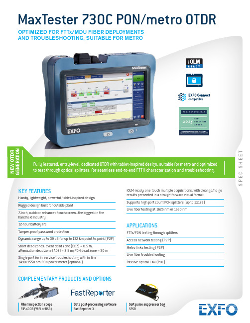
S P E C S H E E TN E W O T D R G E N E R A T I O NKEY FEATURESHandy, lightweight, powerful, tablet-inspired design Rugged design built for outside plant7-inch, outdoor-enhanced touchscreen–the biggest in the handheld industry 12-hour battery lifeTamper-proof password protectionDynamic range up to 39 dB for up to 132 km point-to-point (P2P)Short dead zones: event dead zone (EDZ) = 0.5 m;attenuation dead zone (ADZ) = 2.5 m; PON dead zone = 30 m Single port for in-service troubleshooting with in-line 1490/1550 nm PON power meter (optional)iOLM-ready: one-touch multiple acquisitions, with clear go/no-go results presented in a straightforward visual format Supports high port count PON splitters (up to 1x128)Live fiber testing at 1625 nm or 1650 nmAPPLICATIONSFTTx/PON testing through splitters Access network testing (P2P)Metro links testing (P2P)Live fiber troubleshooting Passive optical LAN (POL)MaxTester 730C PON/metro OTDRFully featured, entry-level, dedicated OTDR with tablet-inspired design, suitable for metro and optimized to test through optical splitters, for seamless end-to-end FTTH characterization and troubleshooting.OPTIMIZED FOR FTTx/MDU FIBER DEPLOYMENTS AND TROUBLESHOOTING, SUITABLE FOR METROCOMPLEMENTARY PRODUCTS AND OPTIONSFiber inspection scope FIP-400B (WiFi or USB)Data post-processing software FastReporter 3Soft pulse suppressor bag SPSBTHE HANDHELD OTDR. . . REINVENTED.The MaxTester 700B/C Series is the first tablet-inspired OTDR line that is handy, lightweight and rugged enough for any outside plant environment. With a 7-inch, outdoor-enhanced touchscreen–the most efficient handheld display in the industry–it delivers an unprecedented user experience. Its intuitive Windows-like GUI ensures a fast learning curve. Plus, its new and improved OTDR 2 environment offers icon-based functions, instant boot-up, automatic macrobend finders as well as improved auto and real-time modes.The MaxTester 700B/C Series is a line of genuine high-performance OTDRs from the world’s leading manufacturer. It delivers EXFO’s tried and true OTDR quality and accuracy along with the best optical performance for right-first-time results, every time. The amazing 12-hour battery life will never let a technician down, and the plug-and-play hardware options, like the VFL, power meter and USB tools, make every technician’s job easier.Most importantly, the MaxTester 700B/C Series is finally bringing the intelligent Optical Link Mapper (iOLM), an intelligent OTDR-based application, to the handheld market. This advanced software turns even the most complex trace analysis into a simple, one-touch task.Ultimately, the MaxTester 700B/C Series is small enough to fit in your hand and big enough to fit all your needs!THE ENTRY-LEVEL SOLUTION DESIGNED FOR ALL YOUR TESTING NEEDSThe MaxTester 730C PON/metro OTDR is optimized to test through optical splitters up to 1x128, ensuring complete end-to-end FTTH characterization. The 1625-nm or 1650-nm, out-of-band, live testing port enables the efficient troubleshooting of active networks without affecting the signal of other clients. Plus, the high dynamic range makes it suitable for metro P2P testing. Other models available:•MaxTester 715B short access and FTTx last-mile installation and troubleshooting•MaxTester 720C LAN/WAN access OTDR—optimized for multimode and singlemode access network construction and troubleshooting SECURE YOUR INVESTMENT AGAINST THEFTProtected instruments have no value on the black market making them completely unappealing to thieves.With our security management option, administrators can define and load a tamper-proof security profileon the MaxTester, displaying a property message on the home screen and securing it with a user password(permanent or renewable).LOOKING FOR ICON-BASED MAPPING?Linear view (included on all EXFO OTDRs)Available on our OTDRs since 2006, the linear view simplifies the reading of an OTDR trace by displaying icons in a linear way for each wavelength. This view converts the graph data points obtained from a traditional single pulse trace into reflective, non-reflective or splitter icons. With applied pass/fail thresholds, it becomes easier to pinpoint faults on your link.This improved linear view offers you the flexibility to display both theOTDR graph and its linear view without having to perform a toggleto analyze your fiber link.Although this linear view simplifies OTDR interpretation of a singlepulse-width trace, the user must still set the OTDR parameters.In addition, multiple traces must often be performed in order tofully characterize the fiber links. See the section below to learnabout how the iOLM can perform this automatically and with moreaccurate results.OTDR testing comes withits load of challenges...In response to these challenges, EXFO developed a better way to test fiber optics:application designed to simplify OTDR testing by eliminating the need to configure parameters, and/or analyze and interpret multiple complex OTDR traces. Its advanced algorithms dynamically define the testing parameters, as well as the number of acquisitions that best fit the network under test. By correlating multipulse widths on multiple wavelengths, the iOLM locates and identifiesIn addition to the standard iOLM feature set, you can select added-value features as part of the Order a unit with the iOLM application onlyCOMBORun both iOLM and OTDR applications (Oi code)Add the iOLM software option to your iOLM-ready unit, even while in the fieldGET THE BEST OUT OF YOUR DATA POST-PROCESSING— ONE SOFTWARE DOES IT ALLThis powerful reporting software is the perfect complement to your OTDR, and can be used to create and customize reports to fully address your needs.OPTICAL PLUG-AND-PLAY OPTIONSThe MaxTester features plug-and-play optical options that can be purchased whenever you need them: at the time of your order or later on. In either case, installation is a snap, and can be performed by the user without the need for any software update. Optical power meterEXFO’s high-level power meter (GeX) can measure up to 27 dBm, the highest in the industry. This is essential for hybrid fiber-coaxial (HFC) networks or high-power signals. If used with an auto-lambda/auto-switching compatible light source, the power meter automatically synchronizes on the same wavelength, thus avoiding any risk of mismatched measurement.•Extensive range of connectors•Auto-lambda and auto-switching•Offers measurement storage and reporting•Seven standard calibrated wavelengthsVisual fault locator (VFL)The plug-and-play VFL easily identifies breaks, bends, faulty connectors and splices, in addition to other causes of signal loss. This basic, yet essential troubleshooting tool should be part of every field technician’s toolbox. The VFL visually locates and detects faults over distances of up to 5 km by creating a bright-red glow at the exact location of the fault on singlemode or multimode fibers (available with the optical power meter only).FIBER CONNECTOR INSPECTION AND CERTIFICATION–THE ESSENTIAL FIRST STEP BEFORE ANY OTDR TESTING Taking the time to properly inspect a fiber-optic connector using an EXFO fiber inspection scope can prevent a host of issues from arising further down the line, thus saving you time, money and trouble. Moreover, using a fully automated solution with autofocus capabilities will turn this critical inspection phase into a fast and hassle-free one-step process.Did you know that the connector of your OTDR/iOLM is also critical?The presence of a dirty connector at an OTDR port or launch cable can negatively impact your test results, and even cause permanent damage during mating. Therefore, it is critical to regularly inspect these connectors to ensure that they are free of any contamination. Making inspection the first step of your OTDR best practices willmaximize the performances of your OTDR and your efficiency.PACKAGED FOR EFFICIENCY1Singlemode OTDR port610/100 Mbit/s Ethernet port11 2Singlemode Live OTDR port7Two USB 2.0 ports12 3Stylus8AC adapter13 4Power meter9Home/switch application andscreen capture (hold)5Visual fault locator10Power on/off/stand by123456789101113SOFTWARE UTILITIESSoftware update Ensure that your MaxTester is up-to-date with the latest software.VNC configuration The Virtual Network Computing (VNC) utility allows technicians to easily remote control the unit via a computer or laptop. Microsoft Internet Explorer Access the Web directly from your device interface.Data mover Transfer all your daily test results quickly and easily.Centralized documentation Instant access to user guides and other relevant documents.Wallpapers Enhance your work environment with colorful and scenic backgrounds.PDF Reader View your reports in PDF format.Bluetooth file sharing Share files between your MaxTester and any Bluetooth-enabled device.WiFi connection WiFi FIP inspection scope interface. Upload test results and browse the Internet.Inspection scope USB or WiFi scope to inspect and analyze connectors.FTP server Exchange files over WiFi to an FTP application on a smartphone for easier file sharing from the field.Security management Tamper-proof security profile with user password (permanent or renewable) and custom property message.SPECIFICATIONS a。
磁性开关SMC

缸径
D-H7型
D-H7C型
D-H7BA型
D-H7NF型
D-H7□W型
D-G5/K5型
D-G5BA型
D-G59F型
D-G5NT型
D-G5□W/K59W型
D-G39/K39型
D-G39A/K39A型
D-F7/J7型
D-J79C型
D-F79F型
D-F7BA型
D-F7BAV型
D-F7□V型
D-F7NT型
无 D-F7□W(V)型
耐热型·2色显示…………………………………………………………………P.1618 宽范围检出型 ……………………………………………………………………P.1619
南
微调电容器磁性开关 ……………………………………………………………P.1620
订制规格 …………………………………………………………………………P.1626
◆有触点磁性开关………………………………………………P.1629
一般(通用)型………………………………………………………………………P.1630 2色显示式…………………………………………………………………………P.1643 耐强磁场·2色显示式……………………………………………………………P.1646 耐热型 ……………………………………………………………………………P.1649
磁 D-A7□H/A80H型
性 D-A73C/A80C型
开 D-A79W型
关 D-A5/A6型
D-A59W型
D-A9型
D-A9□V型
D-E7□A/E80A型
D-Z7/Z8型
D-P7型
D-B3型
执行元件页码索引 (圆型数字为Best No.。)
PMS7003 Digital Universal Particle Concentration S

Digital universal particle concentration sensorPMS7003 series data manualMain characteristics◆Zero false alarm rate◆Real-time response◆Correct data◆Minimum distinguishable particle diameter :0.3 micrometer◆High anti-interference performance because of the patent structure of sixsides shielding◆Optional direction of air inlet and outlet in order to adapt the differentdesign◆Very SlimOverviewPMS7003 is a kind of digital and universal particle concentration sensor, which can be used to obtain the number of suspended particles in the air, i.e. the concentration of particles, and output them in the form of digital interface. This sensor can be inserted into variable instruments related to the concentration of suspended particles in the air or other environmental improvement equipments to provide correct concentration data in time.Working principleLaser scattering principle is used for such sensor, i.e. produce scattering by using laser to radiate suspending particles in the air, then collect scattering light in a certain degree, and finally obtain the curve of scattering light change with time. In the end, equivalent particle diameter and the number of particles with different diameter per unit volume can be calculated by microprocessor based on MIE theory. Please find the functional diagram of each part of sensor from Figure 1 as follows.Figure 1 Functional block diagram of sensor Technical Indexdata is not less than 1000.Note 2:“PM2.5 standard data ” is the “data2” in the appendix.Pin DefinitionFigure 2 Connector DefinitionOutput resultMainly output as the quality and number of each particles with different size per unit volume, the unit volume of particle number is 0.1L and the unit of mass concentration is μg/m³.There are two options for digital output: passive and active. Default mode is active after power up. In this mode sensor would send serial data to the host automatically .The active mode is divided into two sub-modes: stable mode and fast mode. If the concentration change is small the sensor would run at stable mode with the real interval of 2.3s.And if the change is big the sensor would be changed to fast mode automatically with the interval of 200~800ms, the higher of the concentration, the shorter of the interval.Typical CircuitFigure 3 Typical CircuitTypical Output CharacteristicDefinition of axis Y: PM2.5 concentration , unit: μg/m³Definition of axis X: number of samples, unit: timeFigure 4-1 Consistency at 20℃Figure 4-2 Consistency at 43℃Figure 4-3 Consistency at -5℃Figure 4-4 Consistency after 30 days’ runningRelationship of Temperature and ConsistencyDefinition of axis Y: Maximum Error Modulus(%) Definition of axis X: Temperature(℃)Figure 5 Consistency Vs TemperatureEndurance CharacteristicsCircuit Attentions1) DC 5V power supply is needed because the FAN should be driven by 5V.But the high level of data pin is 3.3V. Level conversion unit should beused if the power of host MCU is 5V.2) The SET and RESET pins are pulled up inside so they should not beconnected if without usage.3) PIN7 and PIN8 should not be connected.4) Stable data should be got at least 30 seconds after the sensor wakeupfrom the sleep mode because of the fan’s performance.Installation Attentions1) Metal shell is connected to the GND so be careful not to let it shorted withthe other parts of circuit except GND.2) The best way of install is making the plane of inset and outset closely tothe plane of the host. Or some shield should be placed between inset and outset in order to prevent the air flow from inner loop.3) The blowhole in the shell of the host should not be smaller than the inset.4) The sensor should not be installed in the air flow way of the air cleaner orshould be shielded by some structure.5) The sensor should be installed at least 20cm higher than the grand inorder to prevent it from blocking by the flock dust.6) Do not break up the sensor.Other Attentions1) Only the consistency of all the PM sensors of PLANTOWER is promisedand ensured. And the sensor should not be checked with any third party equipment.2) The sensor is usually used in the common indoor environment. So someprotection must be added if using in the conditions as followed:a) The time of concentration ≥300μg/m³is longer than 50% of thewhole year or concentration≥500μg/m³ i s longer than20% of thewhole year.b) Kitchenc) Water mist condition such as bathroom or hot spring.d) outdoorPart Number DefinitionPhysical Size (mm)Appendix I:PMS7003 transport protocol-Active Mode Default baud rate:9600bps Check bit:None Stop bit:1 bitNote: CF=1 should be used in the factory environment .Appendix II:PMS7003 transport protocol-Passive Mode Default baud rate:9600bps Check bit:None Stop bit:1 bit Host Protocol1.2.Answer0xe2: 32 bytes , same as appendix I3.Verify Bytes :Add of all the bytes except verify bytes.。
施耐德 NSC160S TM160D 断路器Osmart NSC 数据表

Product data sheetCharacteristicsNSC160S3160NNSC160S TM160D 断路器 - 3P/3d主要信息产品系列Osmart NSC 产品类型断路器产品短名NSC160S Rated current 160 A 断路器应用配电保护极数3P额定电流 [In]160 A 在…上 40 °C分断能力25 KA Icu 在…上 220/240 V AC 50/60 Hz 符合 IEC 60947-2 18 KA Icu 在…上 380 V AC 50/60 Hz 符合 IEC 60947-2 18 KA Icu 在…上 400 V AC 50/60 Hz 符合 IEC 60947-2补充信息保护极说明3D 断路器型号S 电网类型AC 电网频率50/60 Hz 控制类型手柄安装类型固定式安装方式底板安装连接方式-上端前连接连接方式-下端前连接额定绝缘电压 [Ui]690 V 符合 IEC 60947-2额定冲击耐受电压 [Uimp]6 KV conforming to IEC 60947-2额定工作电压 [Ue]440 V AC 50/60 Hz 符合 IEC 60947-2使用类别AC类额定使用短路分断能力[Ics]50 % 在…上 380/400 V AC 50/60 Hz 符合 IEC 60947-2 50 % 在…上 220/240 V AC 50/60 Hz 符合 IEC 60947-2机械寿命10000 次电气寿命5000 次 符合 IEC 60947-2相间距35 Mm 脱扣器名称TM-D 脱扣器类型热磁式脱扣器额定值160 A 在…上 40 °C 保护类型短路保护 (磁保护) 过载保护 (热保护)长延时电流整定类型固定式长延时电流整定值 [Ir] 1 In 长延时时间整定类型固定式T h e i n f o r m a t i o n p r o v i d e d i n t h i s d o c u m e n t a t i o n c o n t a i n s g e n e r a l d e s c r i p t i o n s a n d /o r t e c h n i c a l c h a r a c t e r i s t i c s o f t h e p e r f o r m a n c e o f t h e p r o d u c t s c o n t a i n e d h e r e i n .T h i s d o c u m e n t a t i o n i s n o t i n t e n d e d a s a s u b s t i t u t e f o r a n d i s n o t t o b e u s e d f o r d e t e r m i n i n g s u i t a b i l i t y o r r e l i a b i l i t y o f t h e s e p r o d u c t s f o r s p e c i f i c u s e r a p p l i c a t i o n s .I t i s t h e d u t y o f a n y s u c h u s e r o r i n t e g r a t o r t o p e r f o r m t h e a p p r o p r i a t e a n d c o m p l e t e r i s k a n a l y s i s , e v a l u a t i o n a n d t e s t i n g o f t h e p r o d u c t s w i t h r e s p e c t t o t h e r e l e v a n t s p e c i f i c a p p l i c a t i o n o r u s e t h e r e o f .N e i t h e r S c h n e i d e r E l e c t r i c I n d u s t r i e s S A S n o r a n y o f i t s a f f i l i a t e s o r s u b s i d i a r i e s s h a l l b e r e s p o n s i b l e o r l i a b l e f o r m i s u s e o f t h e i n f o r m a t i o n c o n t a i n e d h e r e i n .瞬时保护电流整定类型固定式短路瞬时保护1600 KA高度165 Mm宽度105 Mm深度60 Mm净重 1.3 Kg环境符合标准IEC 60947-2产品认证CE污染等级 3 符合 IEC 60947运行温度-25…70 °C贮存环境温度-35…85 °C包装单位Unit Type of Package 1PCENumber of Units in Package 11Package 1 Height14.51 CmPackage 1 Width18.22 CmPackage 1 Length11.37 CmPackage 1 Weight 1.517 KgUnit Type of Package 2CARNumber of Units in Package 28Package 2 Height26 CmPackage 2 Width30.6 CmPackage 2 Length39.7 CmPackage 2 Weight12.73 KgUnit Type of Package 3PALNumber of Units in Package 3128Package 3 Height106 CmPackage 3 Width62 CmPackage 3 Length80.5 CmPackage 3 Weight220.8 Kg可持续性产品类型Green Premium 产品REACh法规REACh 声明REACh(不含 SVHC)是欧盟ROHS指令符合豁免条件无汞是RoHS 豁免信息是环境披露产品环境文件流通资料无需具体的回收操作循环配置文件合同保修保修单18 个月Product Life Status :Commercialised。
SATEC PRO EM235 快速入门指南说明书

This guide instructs the user on installation, wiring, configuring and operating the EM235 multi-meter. This guide does not substitute the full user manual or the detailed safety instructions. To download the manual and other related material, please visit our website: .Warning! Only a licensed electrician may perform the installation and wiring of the EM235.Figure 1: EM235 front panelINSTALLATIONThe PRO EM235 is designed exclusively for installation on DIN-rail.Please note to leave room for future expansion : when installing a basic unit (without modules), it is recommended to maintain a minimal gap of 30-100mm to the right of the unit, allowing future installation of additional detachable SATEC modules (figure 5; depending on number of added modules, 17.8mm each).Figure 2: Opening the latchThe following steps (Figure 3) correspond with a low-voltage three phase network:1.Make sure all power sources are disconnected.2.Make sure that your designated power supply corresponds with the unit's rating.3.Connect the power supply (bottom-left of front panel) via 12 AWG wires and adesignated circuit breaker.4.Standard external current transformers: connect the CT's (14 AWG minimum) "+" pole tothe device's I1+ current input (unit’s bottom right of front panel, as in figure 3) and the "-" pole to the adjacent I1- current input. Repeat this for the following two phases, I2 and I3. Verify proper polarity in your connections in accordance with the arrow printed on the external CTs.“HACS” CTs: connect the red/white wire to the "+" terminal and the black/orange (colors vary according to the CT model) wire to the "-" terminal.5.Connect the voltage measurement inputs (22-12 AWG; bottom-center of front panel).6.Connect the com wire (26-12 AWG, shielded) to COM1 (RS485, top-left of front panel).7.Power-on the unit.Figure 3: Typical wye installationThe PRO EM235is operated via the LCD display, 2 LEDs and 4 pushbuttons (figure 1: front panel).When powered on, the device will default to displaying voltages, for basic setup back up (<- button) to the home screen navigate with arrows to “setup” (select with ), enter default password (“9”) and select (“apply”). Open “general setup” to reveal “basic setup” for configuration. See screenshot sequence in figure 4, below.Figure 4: Screenshot sequence for basic setup1.DO NOT HOT-SWAP. When adding/removing modules, make sure the unit isdisconnected from power supply2.Remove cover (sticker on right side of unit) to reveal port3.Attach the module tightly and tighten the clips4.Power on the unitFigure 5: module expansion, front panel view1.Default password: 92.Default IP: 192.168.0.203 (ETH1)3.Default current mode (HACS model): Alternating Current (AC)4.Default serial com settings (RS485): 19,200 Baud rate; address = 15.For convenient configuration please use SATEC’s PAS engineering software, connectingyour PC to the USB port (type C) at the right side of the front panel)To download PAS (free): /power-analysis-softwaremake sure to update .exe file with the most recent update available on webpageCopyright © 2021 SATEC Ltd.。
- 1、下载文档前请自行甄别文档内容的完整性,平台不提供额外的编辑、内容补充、找答案等附加服务。
- 2、"仅部分预览"的文档,不可在线预览部分如存在完整性等问题,可反馈申请退款(可完整预览的文档不适用该条件!)。
- 3、如文档侵犯您的权益,请联系客服反馈,我们会尽快为您处理(人工客服工作时间:9:00-18:30)。
+/- 1mA 0-20 mA 4-20 mA 0-1 mA
分时计费 (TOU), 8 种整体化和电能/需量费率登记 x 8 种费率, 4 种季节 x 4 种日计费类型, 每天 8 种费率变化, 容易编程的费率时间表, 电能和最大需量读数的自动日历数据图表 (总量和费率寄存器)
1. RS232
2. RS485
高达 32 个装置
3. TCP/IP
以太网 10/100 BaseT
4. Modem
56K 拨号 modL SPECIFICATIONS 技术参数
PM175
电压 (10-120% FS) 电流 (10-200% FS), 起始电流 0.1% FS 中性电流 频率 功率因素 有功功率(W) 无功功率 (Var) 视在功率 (VA) 有功电度 (W.h.)
无功电度 (War.h.) 视在电度 (VA.h.)
总谐波失真 THD 总需量失真 TDD 温度系数 输入电流消耗 测量电流范围
精度(读数)
0.2% 0.2% 0.4% 0.02% 0.2% 0.2% 0.3% 0.2% 0.2S 级 0.2S 级 遵守 IEC 62053-22:2003 0.2S 级 遵守 IEC 62053-22:2003, |PF|<0.9 0.2S 级 0.2S 级 遵守 IEC 62053-22:2003 0.1% 1.5% 0.008% / οC 小于 0.1 VA 1% 至 200%
全谐波分析仪
电压和电流单次谐波高达第50次
电压和电流总谐波失真THD 电流TDD、K因素 谐波功率和谐波流量(谐波方向)
电压间谐波高达第50次 电压和电流、谐波频谱和谐波角
闪烁: IEC 61000 瞬态记录
最小宽度: 156ms@50Hz
凹陷/膨胀检测 自动报告 实时时钟
符合谐波标准:IEEE1159,G5/4
记录间隔从1到9999秒 支持可编程内存分区
内存
1 MB 非易失性记录内存 针对事件记录、数据记录和波形记录的全部可 编程内存分区
控制选项
2 路继电器输出 4 路数字量输入 4 路模拟量输入(可选项) 最高达16路模拟量输出(可选项)
通讯
两个通讯端口; 通讯可选项:
COM1: RS232/244/485 56K 拨号调制解调器 以太网 10/100 基数 T, eXpertpowerTM 可用 COM2: RS422/485
5A 二次 操作范围: 连续 10A 有效值负荷: <0.1 VA 过载承受: 15A 连续有效值, 300A 持续1秒有效值
1A 二次 操作范围: 连续 2A 有效值负荷: <0.02 VA 过载承受: 6A 连续有效值, 80A 持续1秒有效值
3排高亮度LED显示提供简单明了的本地测量读数。该显示模块可以自由拆卸,并且可以安装在距离 测量本体装置1000米的场所。 LCD 彩色液晶触摸屏图形显示器 (可选项)
PM175 高端电能质量分析仪
高端电能质量分析仪
BENEFITS 好处
PM175 是一个结构紧凑、具有电能质量分析能力的多 功能三相测控和计费仪表。PM175 特别的设计能够满 足从配电盘厂到变电站操作人员等众多用户的需求,3排 高亮度LED显示提供简单明了的本地读数,其显示模块 可自由拆卸,并且它与装置本身的最远安装连接距离能 够到达1000米。
10 Milltown Court, Union NJ 07083, USA Tel: (908) 686-9510 Fax: (908) 686-9520
satec@
FEATURES 特性
测量
0.2S 级计费精度 每周波128个采样真正有效值测量 快速、实时、逐周波测量 四象限测量 最小/最大值(瞬时和需量)
TECHNICAL SPECIFICATIONS 技术参数
参数
外形尺寸 重量 电压输入 电流输入
显示 继电器输出 可选模拟输入/输出
Energy
描述
高: 114 mm; 宽: 127 mm; 长: 114 mm
1.23 公斤 / 2.7 磅.
操作范围: 690 VAC line-to-line, 400 VAC line-to-neutral. 直接输入和通过PT输入 (高达 828 VAC line-to-line, 高达 480 VAC line-to-neutral)
符合标准
精度满足 ANSI C12.20-1998
UL File #E129258 (认证中)
通过认证包括: EMC: 89/336/EEC as amended by 92/31/EEC and 93/68/EEC LVD: 72/23/EEC as amended by 93/68/EEC and 93/465/EEC
声明符合以下统一标准: EN55011: 1991 EN50082-1:1992 EN61010-1:1993 A2/1995 EN50081-2 Generic Emission Standard—Industrial Environment EN50082-2 Generic Immunity Standard—Industrial Environment EN55022: 1994 Class A EN61000-4-2 ENV50140:1983 ENV50204:1995 (900MHz) ENV50141: 1993 EN61000-4-4:1995 EN61000-4-8:1993
接线配置
接受所有接线方式,可选择通过前面板或通过通讯。
电能测量
精度:0.2S级,符合IEC62053-22:2003
EN50160 电能质量记录仪
EN50160 遵守统计, EN50160 谐波调查统计, 板载电能质量分析仪; 可编程门限值和迟滞; 现成的使用报告; IEEE519 电能质量。
定制 EN50160 电能质量记录仪
频率 实时时钟 精度 负荷 环境条件 通讯
质量保证 精度保证
15 Hz ~ 480 Hz 精度: 标准误差 15秒/月 @ 25οC
0.2S级, 0.2S 级遵守IEC62053-22:2003
8 VA
从 -20οC 到 +60οC 湿度: 0 to 95% 无冷凝
Modbus RTU 和 Modbus ASCII 通讯协议
两个通讯端口可以通过补充通讯或者用户数据采集软件 进行本地、远程自动抄表读数和设置。不同通讯选项可 用于包括公共电话线、局域网和互联网的远程通讯。
TOU 分时计费电能测量 完备的内置EN50160报告 0.2S 级精度 通讯平台和各种协议:
电话调制解调器 蜂窝调制解调器 TCP/IP协议 以太网 Profibus DP 测量符合如下电能质量标准: EN50160 IEC6100-4-7 谐波 & 间谐波 IEC61000 闪变 CBEMA/ITIC IEEE519 & IEEE1159
30 ppm 实时时钟 GPS同步脉冲输入
波形记录
两个独立但同步的波形记录器每个都记录完整的 三相电压和三相电流波形 记录分辨率为32并每周波高达128个采样
高达16个预故障周波和2000个后故障周波
支持可编程内存分区
事件记录
可编程的1 ms 时间戳记 支持可编程内存分区
数据记录
16个可编程数据记录表格,每个表格高达16种参数