土木工程外文翻译
(完整)土木工程外文翻译

原文Prestressed ConcreteConcrete is strong in compression, but weak in tension: Its tensile strength varies from 8 to 14 percent of its compressive strength。
Due to such a low tensile capacity, flexural cracks develop at early stages of loading. In order to reduce or prevent such cracks from developing, a concentric or eccentric force is imposed in the longitudinal direction of the structural element. This force prevents the cracks from developing by eliminating or considerably reducing the tensile stresses at the critical midspan and support sections at service load, thereby raising the bending, shear, and torsional capacities of the sections。
The sections are then able to behave elastically, and almost the full capacity of the concrete in compression can be efficiently utilized across the entire depth of the concrete sections when all loads act on the structure.Such an imposed longitudinal force is called a prestressing force, i.e., a compressive force that prestresses the sections along the span of the structural element prior to the application of the transverse gravity dead and live loads or transient horizontal live loads。
土木工程专业英语带译文
13
Key characteristics Three physical characteristics give reinforced concrete its special
12
Chapter 6
If a material with high strength in tension, such as steel, is placed in concrete, then the composite material, reinforced concrete, resists not only compression but also bending and other direct tensile actions. A reinforced concrete section where the concrete resists the compression and steel resists the tension can be made into almost any shape and size for the construction industry.
钢筋混凝土是由混凝土,钢筋(钢筋),钢筋 网(钢筋网),钢板网,钢板或纤维组成,这些被 用来加强混凝土的张力。 它由法国园丁约瑟夫·莫 尼尔于1849年发明,并于1867年获得专利。混凝 土仅指用钢或钢加固的混凝土。 5
• Other materials used to reinforce concrete can be organic and inorganic fibres as well as composites in different forms. Concrete is strong in compression, but weak in tension, thus adding reinforcement increases the strength in tension. In addition, the failure strain of concrete in tension is so low that the reinforcement has to hold the cracked sections together. For a strong, ductile and durable construction the reinforcement shall have the following properties:
土木工程专业英语词汇(整理版)99317
第一部分必须掌握,第二部分尽量掌握第一部分:1 Finite Element Method 有限单元法2 专业英语Specialty English3 水利工程Hydraulic Engineering4 土木工程Civil Engineering5 地下工程Underground Engineering6 岩土工程Geotechnical Engineering7 道路工程Road (Highway) Engineering8 桥梁工程Bridge Engineering9 隧道工程Tunnel Engineering10 工程力学Engineering Mechanics11 交通工程Traffic Engineering12 港口工程Port Engineering13 安全性safety17木结构timber structure18 砌体结构masonry structure19 混凝土结构concrete structure20 钢结构steelstructure21 钢-混凝土复合结构steel and concrete composite structure22 素混凝土plain concrete23 钢筋混凝土reinforced concrete24 钢筋rebar25 预应力混凝土pre-stressed concrete26 静定结构statically determinate structure27 超静定结构statically indeterminate structure28 桁架结构truss structure29 空间网架结构spatial grid structure30 近海工程offshore engineering31 静力学statics32运动学kinematics33 动力学dynamics34 简支梁simply supported beam35 固定支座fixed bearing36弹性力学elasticity37 塑性力学plasticity38 弹塑性力学elaso-plasticity39 断裂力学fracture Mechanics40 土力学soil mechanics41 水力学hydraulics42 流体力学fluid mechanics43 固体力学solid mechanics44 集中力concentrated force45 压力pressure46 静水压力hydrostatic pressure47 均布压力uniform pressure48 体力body force49 重力gravity 50 线荷载line load51 弯矩bending moment52 torque 扭矩53 应力stress54 应变stain55 正应力normal stress56 剪应力shearing stress57 主应力principal stress58 变形deformation59 内力internal force60 偏移量挠度deflection61 settlement 沉降62 屈曲失稳buckle63 轴力axial force64 允许应力allowable stress65 疲劳分析fatigue analysis66 梁beam67 壳shell68 板plate69 桥bridge70 桩pile71 主动土压力active earth pressure72 被动土压力passive earth pressure73 承载力load-bearing capacity74 水位water Height75 位移displacement76 结构力学structural mechanics77 材料力学material mechanics78 经纬仪altometer79 水准仪level80 学科discipline81 子学科sub-discipline82 期刊journal ,periodical83文献literature84 ISSN International Standard Serial Number 国际标准刊号85 ISBN International Standard Book Number 国际标准书号86 卷volume87 期number 88 专著monograph89 会议论文集Proceeding90 学位论文thesis, dissertation91 专利patent92 档案档案室archive93 国际学术会议conference94 导师advisor95 学位论文答辩defense of thesis96 博士研究生doctorate student97 研究生postgraduate98 EI Engineering Index 工程索引99 SCI Science Citation Index 科学引文索引100ISTP Index to Science and Technology Proceedings 科学技术会议论文集索引101 题目title102 摘要abstract103 全文full-text104 参考文献reference105 联络单位、所属单位affiliation106 主题词Subject107 关键字keyword108 ASCE American Society of Civil Engineers 美国土木工程师协会109 FHWA Federal Highway Administration 联邦公路总署110 ISO International Standard Organization111 解析方法analytical method112 数值方法numerical method113 计算computation114 说明书instruction第二部分:岩土工程专业词汇1.geotechnical engineering岩土工程2.foundation engineering基础工程3.soil, earth土4.soil mechanics土力学cyclic loading周期荷载unloading卸载reloading再加载viscoelastic foundation粘弹性地基viscous damping粘滞阻尼shear modulus剪切模量5.soil dynamics土动力学6.stress path应力路径7.numerical geotechanics 数值岩土力学二. 土的分类 1.residual soil残积土groundwater level地下水位 2.groundwater 地下水groundwater table地下水位3.clay minerals粘土矿物 4.secondary minerals次生矿物ndslides滑坡6.bore hole columnar section钻孔柱状图7.engineering geologic investigation工程地质勘察8.boulder漂石9.cobble卵石10.gravel砂石11.gravelly sand砾砂12.coarse sand粗砂13.medium sand中砂14.fine sand细砂15.silty sand粉土16.clayey soil粘性土17.clay粘土18.silty clay粉质粘土19.silt粉土20.sandy silt砂质粉土21.clayey silt粘质粉土22.saturated soil饱和土23.unsaturated soil非饱和土24.fill (soil)填土25.overconsolidated soil超固结土26.normally consolidated soil正常固结土27.underconsolidated soil欠固结土28.zonal soil区域性土29.soft clay软粘土30.expansive (swelling) soil膨胀土31.peat泥炭32.loess黄土33.frozen soil冻土24.degree of saturation饱和度25.dry unit weight 干重度26.moist unit weight湿重度45.ISSMGE=International Society for Soil Mechanics and Geotechnical Engineering 国际土力学与岩土工程学会四. 渗透性和渗流1.Darcy’s law 达西定律2.piping管涌3.flowing soil流土4.sand boiling砂沸5.flow net流网6.seepage渗透(流)7.leakage渗流8.seepage pressure渗透压力9.permeability 渗透性10.seepage force渗透力11.hydraulic gradient水力梯度12.coefficient of permeability渗透系数五. 地基应力和变形1.soft soil软土2.(negative) skin friction of driven pile打入桩(负)摩阻力3.effective stress有效应力4.total stress总应力5.field vane shear strength十字板抗剪强度6.low activity低活性7.sensitivity灵敏度8.triaxial test三轴试验9.foundation design基础设计10.recompaction再压缩11.bearing capacity承载力12.soil mass土体13.contact stress (pressure)接触应力(压力)14.concentrated load集中荷载15.a semi-infinite elastic solid半无限弹性体16.homogeneous均质17.isotropic各向同性18.strip footing条基19.square spread footing方形独立基础20.underlying soil (stratum ,strata)下卧层(土)21.dead load =sustained load恒载持续荷载22.live load活载23.short –term transient load短期瞬时荷载24.long-term transient load长期荷载25.reduced load折算荷载26.settlement沉降27.deformation变形28.casing套管29.dike=dyke堤(防)30.clay fraction粘粒粒组31.physical properties物理性质32.subgrade路基33.well-graded soil级配良好土34.poorly-graded soil级配不良土35.normal stresses正应力36.shear stresses剪应力37.principal plane主平面38.major (intermediate, minor) principal stress最大(中、最小)主应力39.Mohr-Coulomb failure condition摩尔-库仑破坏条件40.FEM=finite element method有限元法41.limit equilibrium method极限平衡法42.pore water pressure孔隙水压力43.preconsolidation pressure先期固结压力44.modulus of compressibility压缩模量45.coefficent of compressibility压缩系数pression index压缩指数47.swelling index回弹指数48.geostatic stress自重应力49.additional stress附加应力50.total stress总应力51.final settlement最终沉降52.slip line滑动线六. 基坑开挖与降水 1 excavation开挖(挖方) 2 dewatering(基坑)降水3 failure of foundation基坑失稳4 bracing of foundation pit基坑围护5 bottom heave=basal heave (基坑)底隆起6 retaining wall挡土墙7 pore-pressure distribution孔压分布8 dewatering method降低地下水位法9 well point system井点系统(轻型)10 deep well point深井点11 vacuum well point真空井点12 braced cuts支撑围护13 braced excavation支撑开挖14 braced sheeting支撑挡板七. 深基础--deep foundation 1.pile foundation桩基础1)cast –in-place灌注桩diving casting cast-in-place pile沉管灌注桩bored pile钻孔桩special-shaped cast-in-place pile 机控异型灌注桩piles set into rock嵌岩灌注桩rammed bulb pile夯扩桩2)belled pier foundation钻孔墩基础drilled-pier foundation 钻孔扩底墩under-reamed bored pier3)precast concrete pile预制混凝土桩4)steel pile钢桩steel pipe pile钢管桩steel sheet pile钢板桩5)prestressed concrete pile预应力混凝土桩prestressed concrete pipe pile预应力混凝土管桩2.caisson foundation 沉井(箱)3.diaphragm wall地下连续墙截水墙4.friction pile摩擦桩5.end-bearing pile端承桩6.shaft竖井;桩身7.wave equation analysis波动方程分析8.pile caps承台(桩帽)9.bearing capacity of single pile单桩承载力teral pile load test单桩横向载荷试验11.ultimate lateral resistance of single pile单桩横向极限承载力12.static load test of pile单桩竖向静荷载试验13.vertical allowable load capacity单桩竖向容许承载力14.low pile cap低桩承台15.high-rise pile cap高桩承台16.vertical ultimate uplift resistance of single pile单桩抗拔极限承载力17.silent piling静力压桩18.uplift pile抗拔桩19.anti-slide pile抗滑桩20.pile groups群桩21.efficiency factor of pile groups群桩效率系数(η)22.efficiency of pile groups群桩效应23.dynamic pile testing桩基动测技术24.final set最后贯入度25.dynamic load test of pile桩动荷载试验26.pile integrity test桩的完整性试验27.pile head=butt桩头28.pile tip=pile point=pile toe桩端(头)29.pile spacing桩距30.pile plan桩位布置图31.arrangement of piles =pile layout 桩的布置32.group action群桩作用33.end bearing=tip resistance桩端阻34.skin(side) friction=shaft resistance桩侧阻35.pile cushion桩垫36.pile driving(by vibration) (振动)打桩37.pile pulling test拔桩试验38.pile shoe桩靴39.pile noise打桩噪音40.pile rig打桩机九. 固结consolidation1.Terzzaghi’s consolidation theory太沙基固结理论2.Barraon’s consolidation theory巴隆固结理论3.Biot’s consolidation theory比奥固结理论4.over consolidation ration (OCR)超固结比5.overconsolidation soil超固结土6.excess pore water pressure超孔压力7.multi-dimensional consolidation多维固结8.one-dimensional consolidation一维固结9.primary consolidation主固结10.secondary consolidation次固结11.degree of consolidation固结度12.consolidation test固结试验13.consolidation curve固结曲线14.time factor Tv时间因子15.coefficient of consolidation固结系数16.preconsolidation pressure前期固结压力17.principle of effective stress有效应力原理18.consolidation under K0 condition K0固结十. 抗剪强度shear strength 1.undrained shear strength不排水抗剪强度2.residual strength残余强度3.long-term strength长期强度4.peak strength峰值强度5.shear strain rate剪切应变速率6.dilatation剪胀7.effective stress approach of shear strength 剪胀抗剪强度有效应力法8.total stress approach of shear strength抗剪强度总应力法9.Mohr-Coulomb theory莫尔-库仑理论10.angle of internal friction内摩擦角11.cohesion粘聚力12.failure criterion破坏准则13.vane strength十字板抗剪强度14.unconfined compression无侧限抗压强度15.effective stress failure envelop有效应力破坏包线16.effective stress strength parameter有效应力强度参数十一. 本构模型--constitutive model1.elastic model弹性模型2.nonlinear elastic model非线性弹性模型3.elastoplastic model弹塑性模型4.viscoelastic model粘弹性模型5.boundary surface model边界面模型6.Duncan-Chang model邓肯-张模型7.rigid plastic model 刚塑性模型8.cap model盖帽模型9.work softening加工软化10.work hardening加工硬化11.Cambridge model剑桥模型12.ideal elastoplastic model理想弹塑性模型13.Mohr-Coulomb yield criterion莫尔-库仑屈服准则14.yield surface屈服面15.elastic half-space foundation model弹性半空间地基模型16.elastic modulus弹性模量17.Winkler foundation model 文克尔地基模型十二. 地基承载力--bearing capacity of foundation soil 1.punching shear failure冲剪破坏2.general shear failure整体剪切破化 3.local shear failure局部剪切破坏 4.state of limit equilibrium极限平衡状态5.critical edge pressure临塑荷载6.stability of foundation soil地基稳定性7.ultimate bearing capacity of foundation soil地基极限承载力8.allowable bearing capacity of foundation soil地基容许承载力十三. 土压力--earth pressure1.active earth pressure主动土压力2.passive earth pressure 被动土压力3.earth pressure at rest静止土压力4.Coulomb’s earth pressure theory库仑土压力理论5.Rankine’s earth pressure theory朗金土压力理论十四. 土坡稳定分析--slope stability analysis1.angle of repose休止角2.Bishop method毕肖普法3.safety factor of slope边坡稳定安全系数4.Fellenius method of slices费纽伦斯条分法5.Swedish circle method 瑞典圆弧滑动法6.slices method条分法十五. 挡土墙--retaining wall1.stability of retaining wall挡土墙稳定性2.foundation wall基础墙3.counter retaining wall扶壁式挡土墙4.cantilever retaining wall悬臂式挡土墙5.cantilever sheet pile wall悬臂式板桩墙6.gravity retaining wall重力式挡土墙7.anchored plate retaining wall锚定板挡土墙8.anchored sheet pile wall锚定板板桩墙十六. 板桩结构物--sheet pile structure 1.steel sheet pile钢板桩 2.reinforced concrete sheet pile钢筋混凝土板桩3.steel piles钢桩4.wooden sheet pile木板桩5.timber piles 木桩十七. 浅基础--shallow foundation 1.box foundation箱型基础 2.mat(raft) foundation片筏基础 3.strip foundation条形基础 4.spread footing扩展基础pensated foundation 补偿性基础6.bearing stratum持力层7.rigid foundation刚性基础8.flexible foundation柔性基础9.embedded depth of foundation基础埋置深度 foundation pressure基底附加应力11.structure-foundation-soil interaction analysis上部结构-基础-地基共同作用分析十八. 土的动力性质--dynamic properties of soils1.dynamic strength of soils动强度2.wave velocity method 波速法3.material damping材料阻尼4.geometric damping 几何阻尼5.damping ratio阻尼比6.initial liquefaction初始液化7.natural period of soil site地基固有周期8.dynamic shear modulus of soils动剪切模量9.dynamic ma 二十. 地基基础抗震 1.earthquake engineering地震工程2.soil dynamics土动力学3.duration of earthquake地震持续时间 4.earthquake response spectrum地震反应谱5.earthquake intensity地震烈度6.earthquake magnitude震级7.seismic predominant period地震卓越周期8.maximum acceleration of earthquake地震最大加速度二十一. 室内土工实验1.high pressure consolidation test高压固结试验2.consolidation under K0 condition K0固结试验 3.falling head permeability变水头试验4.constant head permeability常水头渗透试验5.unconsolidated-undrained triaxial test不固结不排水试验(UU)6.consolidated undrained triaxial test固结不排水试验(CU)7.consolidated drained triaxial test固结排水试验(CD)paction test击实试验9.consolidated quick direct shear test固结快剪试验10.quick direct shear test快剪试验11.consolidated drained direct shear test慢剪试验12.sieve analysis筛分析13.geotechnical model test土工模型试验14.centrifugalmodel test离心模型试验15.direct shear apparatus直剪仪16.direct shear test直剪试验17.direct simple shear test直接单剪试验18.dynamic triaxial test三轴试验19.dynamic simple shear 动单剪20.free(resonance)vibration column test自(共)振柱试验二十二. 原位测试1.standard penetration test (SPT)标准贯入试验 2.surface wave test (SWT)表面波试验 3.dynamic penetration test(DPT)动力触探试验4.static cone penetration (SPT) 静力触探试验 5.plate loading test静力荷载试验teral load test of pile 单桩横向载荷试验7.static load test of pile 单桩竖向荷载试验8.cross-hole test 跨孔试验9.screw plate test螺旋板载荷试验10.pressuremeter test旁压试验11.light sounding轻便触探试验12.deep settlement measurement深层沉降观测13.vane shear test十字板剪切试验14.field permeability test现场渗透试验15.in-situ pore water pressure measurement 原位孔隙水压量测16.in-situ soil test原位试验。
(完整版)土木工程专业英语翻译
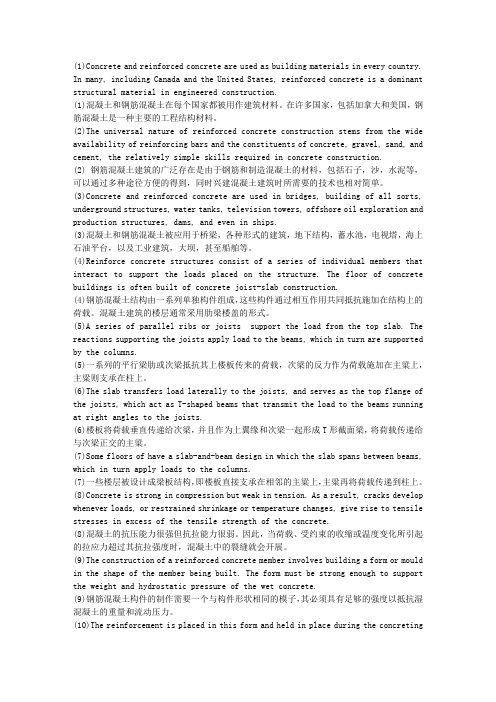
(1)Concrete and reinforced concrete are used as building materials in every country. In many, including Canada and the United States, reinforced concrete is a dominant structural material in engineered construction.(1)混凝土和钢筋混凝土在每个国家都被用作建筑材料。
在许多国家,包括加拿大和美国,钢筋混凝土是一种主要的工程结构材料。
(2)The universal nature of reinforced concrete construction stems from the wide availability of reinforcing bars and the constituents of concrete, gravel, sand, and cement, the relatively simple skills required in concrete construction.(2) 钢筋混凝土建筑的广泛存在是由于钢筋和制造混凝土的材料,包括石子,沙,水泥等,可以通过多种途径方便的得到,同时兴建混凝土建筑时所需要的技术也相对简单。
(3)Concrete and reinforced concrete are used in bridges, building of all sorts, underground structures, water tanks, television towers, offshore oil exploration and production structures, dams, and even in ships.(3)混凝土和钢筋混凝土被应用于桥梁,各种形式的建筑,地下结构,蓄水池,电视塔,海上石油平台,以及工业建筑,大坝,甚至船舶等。
土木工程毕业外文翻译
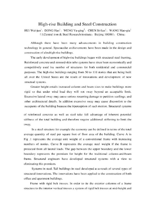
1.Central iron & Steel Research institute, Beijing 100081, China2.Chinese Society for Metals, Beijing 100711, China高层建筑与钢结构HUi Wei-jun,DONG HanWENG Yu-ging,CHEN Si-lian,WANG Mao-giu摘要耐火钢其实就是对火灾有一定抵抗能力的钢材,日本认为耐火钢是焊接结构用轧制钢材的一类,在我国它是建筑用低合金钢的一种。
耐火钢于普通的建筑用钢不同,它要求具有良好的耐高温性能,作为常温下的承载材料,只要求在遇到火灾的较短时间内(1到3小时)高温条件下能够保持高的屈服强度,常温下钢材强度的2/3相当于该材料的长期允许应力值,当发生火灾时,如果耐火钢的屈服点仍然在此值以上,建筑物就不会倒塌。
因此,就要求耐火钢在一定高温下的屈服不低于室温下屈服强度的2/3。
本文研究的目的在于研究提高耐火港的强韧性、抗震性和耐火性能。
关键字高层建筑;钢结构;发展应用1.前言近年来,虽然一般的建筑结构设计取得了很大的进步,但是取得显著成绩的还要数超高层建筑结构设计。
最初的高层建筑设计是从钢结构的设计开始的。
钢筋混凝土和受力外包钢筒系统运用起来是比较经济的系统,被有效地运用于大批的民用建筑和商业建筑中。
50层到100层的建筑被成为超高层建筑。
而这种建筑在美国被广泛的应用是由于新的结构系统的发展和创新。
这样的高度需要大柱和梁的尺寸,这样以来可以使建筑物更加坚固以至于在允许的限度范围内承受风荷载而不产生弯曲和倾斜。
过分的倾斜会导致建筑物的隔离构件、顶棚以及其它建筑细部产生循环破坏。
除此之外,过大的摇动也会使建筑物的使用者感觉到这样的晃动而产生不舒服的感觉。
无论是钢筋混凝土结构系统还是钢结构系统都充分利用了整个建筑的刚度潜力,因此,不能指望利用多余的刚度来限制侧向位移。
土木工程--外文文献翻译

土木工程--外文文献翻译-CAL-FENGHAI.-(YICAI)-Company One1学院:专业:土木工程姓名:学号:外文出处: Structural Systems to resist (用外文写)Lateral loads附件: 1.外文资料翻译译文;2.外文原文。
附件1:外文资料翻译译文抗侧向荷载的结构体系常用的结构体系若已测出荷载量达数千万磅重,那么在高层建筑设计中就没有多少可以进行极其复杂的构思余地了。
确实,较好的高层建筑普遍具有构思简单、表现明晰的特点。
这并不是说没有进行宏观构思的余地。
实际上,正是因为有了这种宏观的构思,新奇的高层建筑体系才得以发展,可能更重要的是:几年以前才出现的一些新概念在今天的技术中已经变得平常了。
如果忽略一些与建筑材料密切相关的概念不谈,高层建筑里最为常用的结构体系便可分为如下几类:1.抗弯矩框架。
2.支撑框架,包括偏心支撑框架。
3.剪力墙,包括钢板剪力墙。
4.筒中框架。
5.筒中筒结构。
6.核心交互结构。
7. 框格体系或束筒体系。
特别是由于最近趋向于更复杂的建筑形式,同时也需要增加刚度以抵抗几力和地震力,大多数高层建筑都具有由框架、支撑构架、剪力墙和相关体系相结合而构成的体系。
而且,就较高的建筑物而言,大多数都是由交互式构件组成三维陈列。
将这些构件结合起来的方法正是高层建筑设计方法的本质。
其结合方式需要在考虑环境、功能和费用后再发展,以便提供促使建筑发展达到新高度的有效结构。
这并不是说富于想象力的结构设计就能够创造出伟大建筑。
正相反,有许多例优美的建筑仅得到结构工程师适当的支持就被创造出来了,然而,如果没有天赋甚厚的建筑师的创造力的指导,那么,得以发展的就只能是好的结构,并非是伟大的建筑。
无论如何,要想创造出高层建筑真正非凡的设计,两者都需要最好的。
虽然在文献中通常可以见到有关这七种体系的全面性讨论,但是在这里还值得进一步讨论。
设计方法的本质贯穿于整个讨论。
土木工程外文翻译-原文
外文原文Response of a reinforced concrete infilled-frame structure to removal of twoadjacent columnsMehrdad Sasani_Northeastern University, 400 Snell Engineering Center, Boston, MA 02115, UnitedStatesReceived 27 June 2007; received in revised form 26 December 2007; accepted 24January 2008Available online 19 March 2008AbstractThe response of Hotel San Diego, a six-story reinforced concrete infilled-frame structure, is evaluated following the simultaneous removal of two adjacent exterior columns. Analytical models of the structure using the Finite Element Method as well as the Applied Element Method are used to calculate global and local deformations. The analytical results show good agreement with experimental data. The structure resisted progressive collapse with a measured maximum vertical displacement of only one quarter of an inch (6.4 mm). Deformation propagation over the height of the structure and the dynamic load redistribution following the column removal are experimentally and analytically evaluated and described. The difference between axial and flexural wave propagations is discussed. Three-dimensional Vierendeel (frame) action of the transverse and longitudinal frames with the participation of infill walls is identified as the major mechanism for redistribution of loads in the structure. The effects of two potential brittle modes of failure (fracture of beam sections without tensile reinforcement and reinforcing bar pull out) are described. The response of the structure due to additional gravity loads and in the absence of infill walls is analytically evaluated.c 2008 Elsevier Ltd. All rights reserved.Keywords: Progressive collapse; Load redistribution; Load resistance; Dynamic response; Nonlinear analysis; Brittle failure1.IntroductionThe principal scope of specifications is to provide general principles and computation al methods in order to verify safety of structures. The “ safety factor ”, which accor ding to modern trends is independent of the nature and combination of the materials u sed, can usually be defined as the ratio between the conditions. This ratio is also prop ortional to the inverse of the probability ( risk ) of failure of the structure.Failure has to be considered not only as overall collapse of the structure but also as un serviceability or, according to a more precise. Common definition. As the reaching of a “ limit state ” which causes the construction not to accomplish the task it was desi gned for. There are two categories of limit state :(1)Ultimate limit sate, which corresponds to the highest value of the load-bearing cap acity. Examples include local buckling or global instability of the structure; failure of some sections and subsequent transformation of the structure into a mechanism; failure by fatigue; elastic or plastic deformation or creep that cause a substantial change of t he geometry of the structure; and sensitivity of the structure to alternating loads, to fire and to explosions.(2)Service limit states, which are functions of the use and durability of the structure. E xamples include excessive deformations and displacements without instability; early o r excessive cracks; large vibrations; and corrosion.Computational methods used to verify structures with respect to the different safety co nditions can be separated into:(1)Deterministic methods, in which the main parameters are considered as nonrandom parameters.(2)Probabilistic methods, in which the main parameters are considered as random para meters.Alternatively, with respect to the different use of factors of safety, computational meth ods can be separated into:(1)Allowable stress method, in which the stresses computed under maximum loads are compared with the strength of the material reduced by given safety factors.(2)Limit states method, in which the structure may be proportioned on the basis of its maximum strength. This strength, as determined by rational analysis, shall not be less than that required to support a factored load equal to the sum of the factored live load and dead load ( ultimate state ).The stresses corresponding to working ( service ) conditions with unfactored live and dead loads are compared with prescribed values ( service limit state ) . From the four possible combinations of the first two and second two methods, we can obtain some u seful computational methods. Generally, two combinations prevail:(1)deterministic methods, which make use of allowable stresses. (2)Probabilistic meth ods, which make use of limit states.The main advantage of probabilistic approaches is that, at least in theory, it is possible to scientifically take into account all random factors of safety, which are then combin ed to define the safety factor. probabilistic approaches depend upon :(1) Random distribution of strength of materials with respect to the conditions of fabri cation and erection ( scatter of the values of mechanical properties through out the str ucture ); (2) Uncertainty of the geometry of the cross-section sand of the structure ( fa ults and imperfections due to fabrication and erection of the structure );(3) Uncertainty of the predicted live loads and dead loads acting on the structure; (4)U ncertainty related to the approximation of the computational method used ( deviation of the actual stresses from computed stresses ). Furthermore, probabilistic theories me an that the allowable risk can be based on several factors, such as :(1) Importance of the construction and gravity of the damage by its failure; (2)Numbe r of human lives which can be threatened by this failure; (3)Possibility and/or likeliho od of repairing the structure; (4) Predicted life of the structure. All these factors are rel ated to economic and social considerations such as:(1) Initial cost of the construction;(2) Amortization funds for the duration of the construction;(3) Cost of physical and material damage due to the failure of the construction;(4) Adverse impact on society;(5) Moral and psychological views.The definition of all these parameters, for a given safety factor, allows constructio n at the optimum cost. However, the difficulty of carrying out a complete probabilistic analysis has to be taken into account. For such an analysis the laws of the distribution of the live load and its induced stresses, of the scatter of mechanical properties of mat erials, and of the geometry of the cross-sections and the structure have to be known. F urthermore, it is difficult to interpret the interaction between the law of distribution of strength and that of stresses because both depend upon the nature of the material, on t he cross-sections and upon the load acting on the structure. These practical difficulties can be overcome in two ways. The first is to apply different safety factors to the mate rial and to the loads, without necessarily adopting the probabilistic criterion. The seco nd is an approximate probabilistic method which introduces some simplifying assump tions ( semi-probabilistic methods ) . As part of mitigation programs to reduce the likelihood of mass casualties following local damage in structures, the General Services Administration [1] and the Department of Defense [2] developed regulations to evaluate progressive collapse resistance of structures. ASCE/SEI 7 [3] defines progressive collapse as the spread of an initial local failure from element to element eventually resulting in collapse of an entire structure or a disproportionately large part of it. Following the approaches proposed by Ellinwood and Leyendecker [4], ASCE/SEI 7 [3] defines two general methods for structural design of buildings to mitigate damage due to progressive collapse: indirect and direct design methods. General building codes and standards [3,5] use indirect design by increasing overall integrity of structures. Indirect design is also used in DOD [2]. Although the indirect design method can reduce the risk of progressive collapse [6,7] estimation of post-failure performance of structures designed based on such a method is not readily possible. One approach based on direct design methods to evaluate progressive collapse of structures is to study the effects of instantaneous removal of load-bearing elements, such as columns. GSA [1] and DOD [2] regulations require removal of one load bearing element. These regulations are meant to evaluate general integrity of structures and their capacity of redistributing the loads following severe damage to only one element. While such an approach provides insight as to the extent to which the structures are susceptible to progressive collapse, in reality, the initial damage can affect more than just one column. In this study, using analytical results that are verified against experimental data, the progressive collapse resistance of the Hotel San Diego is evaluated, following the simultaneous explosion (sudden removal) of two adjacent columns, one of which was a corner column. In order to explode the columns, explosives were inserted into predrilled holes in the columns. The columns were then well wrapped with a few layers of protective materials. Therefore, neither air blast nor flying fragments affected the structure.2. Building characteristicsHotel San Diego was constructed in 1914 with a south annex added in 1924. The annex included two separate buildings. Fig. 1 shows a south view of the hotel. Note that in the picture, the first and third stories of the hotel are covered with black fabric. The six story hotel had a non-ductile reinforced concrete (RC) frame structure with hollow clay tile exterior infill walls. The infills in the annex consisted of two withes (layers) of clay tiles with a total thickness of about 8 in (203 mm). The height of the first floor was about 190–800 (6.00 m). The height of other floors and that of the top floor were 100–600 (3.20 m) and 160–1000 (5.13 m), respectively. Fig. 2 shows the second floor of one of the annex buildings. Fig. 3 shows a typical plan of this building, whose response following the simultaneous removal (explosion) of columns A2 and A3 in the first (ground) floor is evaluated in this paper. The floor system consisted of one-way joists running in the longitudinal direction (North–South), as shown in Fig. 3. Based on compression tests of two concrete samples, the average concrete compressive strength was estimated at about 4500 psi (31 MPa) for a standard concrete cylinder. The modulus of elasticity of concrete was estimated at 3820 ksi (26 300 MPa) [5]. Also, based on tension tests of two steel samples having 1/2 in (12.7 mm) square sections, the yield and ultimate tensile strengths were found to be 62 ksi (427 MPa) and 87 ksi (600 MPa), respectively. The steel ultimate tensile strain was measured at 0.17. The modulus of elasticity of steel was set equal to 29 000 ksi (200000 MPa). The building was scheduled to be demolished by implosion. As part of the demolition process, the infill walls were removed from the first and third floors. There was no live load in the building. All nonstructural elements including partitions, plumbing, and furniture were removed prior to implosion. Only beams, columns, joist floor and infill walls on the peripheralbeams were present.3. SensorsConcrete and steel strain gages were used to measure changes in strains of beams and columns. Linear potentiometers were used to measure global and local deformations. The concrete strain gages were 3.5 in (90 mm) long having a maximum strain limit of ±0.02. The steel strain gages could measure up to a strain of ±0.20. The strain gages could operate up to a several hundred kHz sampling rate. The sampling rate used in the experiment was 1000 Hz. Potentiometers were used to capture rotation (integral of curvature over a length) of the beam end regions and global displacement in the building, as described later. The potentiometers had a resolution of about 0.0004 in (0.01 mm) and a maximum operational speed of about 40 in/s (1.0 m/s), while the maximum recorded speed in the experiment was about 14 in/s (0.35m/s).4. Finite element modelUsing the finite element method (FEM), a model of the building was developed in the SAP2000 [8] computer program. The beams and columns are modeled with Bernoulli beam elements. Beams have T or L sections with effective flange width on each side of the web equal to four times the slab thickness [5]. Plastic hinges are assigned to all possible locations where steel bar yielding can occur, including the ends of elements as well as the reinforcing bar cut-off and bend locations. The characteristics of the plastic hinges are obtained using section analyses of the beams and columns and assuming a plastic hinge length equal to half of the section depth. The current version of SAP2000 [8] is not able to track formation of cracks in the elements. In order to find the proper flexural stiffness of sections, an iterative procedure is used as follows. First, the building is analyzed assuming all elements are uncracked. Then, moment demands in the elements are compared with their cracking bending moments, Mcr . The moment of inertia of beam and slab segments are reduced by a coefficient of 0.35 [5], where the demand exceeds the Mcr. The exteriorbeam cracking bending moments under negative and positive moments, are 516 k in (58.2 kN m) and 336 k in (37.9 kN m), respectively. Note that no cracks were formed in the columns. Then the building is reanalyzed and moment diagrams are re-evaluated. This procedure is repeated until all of the cracked regions are properly identified and modeled.The beams in the building did not have top reinforcing bars except at the end regions (see Fig. 4). For instance, no top reinforcement was provided beyond the bend in beam A1–A2, 12 inches away from the face of column A1 (see Figs. 4 and 5). To model the potential loss of flexural strength in those sections, localized crack hinges were assigned at the critical locations where no top rebar was present. Flexural strengths of the hinges were set equal to Mcr. Such sections were assumed to lose their flexural strength when the imposed bending moments reached Mcr.The floor system consisted of joists in the longitudinal direction (North–South). Fig. 6 shows the cross section of a typical floor. In order to account for potential nonlinear response of slabs and joists, floors are molded by beam elements. Joists are modeled with T-sections, having effective flange width on each side of the web equal to four times the slab thickness [5]. Given the large joist spacing between axes 2 and 3, two rectangular beam elements with 20-inch wide sections are used between the joist and the longitudinal beams of axes 2 and 3 to model the slab in the longitudinal direction. To model the behavior of the slab in the transverse direction, equally spaced parallel beams with 20-inch wide rectangular sections are used. There is a difference between the shear flow in the slab and that in the beam elements with rectangular sections modeling the slab. Because of this, the torsional stiffness is setequal to one-half of that of the gross sections [9].The building had infill walls on 2nd, 4th, 5th and 6th floors on the spandrel beamswith some openings (i.e. windows and doors). As mentioned before and as part of the demolition procedure, the infill walls in the 1st and 3rd floors were removed before the test. The infill walls were made of hollow clay tiles, which were in good condition. The net area of the clay tiles was about 1/2 of the gross area. The in-plane action of the infill walls contributes to the building stiffness and strength and affects the building response. Ignoring the effects of the infill walls and excluding them in the model would result in underestimating the building stiffness and strength.Using the SAP2000 computer program [8], two types of modeling for the infills are considered in this study: one uses two dimensional shell elements (Model A) and the other uses compressive struts (Model B) as suggested in FEMA356 [10] guidelines.4.1. Model A (infills modeled by shell elements)Infill walls are modeled with shell elements. However, the current version of the SAP2000 computer program includes only linear shell elements and cannot account for cracking. The tensile strength of the infill walls is set equal to 26 psi, with a modulus of elasticity of 644 ksi [10]. Because the formation ofcracks has a significant effect on the stiffness of the infill walls, the following iterative procedure is used to account for crack formation:(1) Assuming the infill walls are linear and uncracked, a nonlinear time history analysis is run. Note that plastic hinges exist in the beam elements and the segments of the beam elements where moment demand exceeds the cracking moment have a reduced moment of inertia.(2) The cracking pattern in the infill wall is determined by comparing stresses in the shells developed during the analysis with the tensile strength of infills.(3) Nodes are separated at the locations where tensile stress exceeds tensile strength. These steps are continued until the crack regions are properly modeled.4.2. Model B (infills modeled by struts)Infill walls are replaced with compressive struts as described in FEMA 356 [10] guidelines. Orientations of the struts are determined from the deformed shape of the structure after column removal and the location of openings.4.3. Column removalRemoval of the columns is simulated with the following procedure.(1) The structure is analyzed under the permanent loads and the internal forces are determined at the ends of the columns, which will be removed.(2) The model is modified by removing columns A2 and A3 on the first floor. Again the structure is statically analyzed under permanent loads. In this case, the internal forces at the ends of removed columns found in the first step are applied externally to the structure along with permanent loads. Note that the results of this analysis are identical to those of step 1.(3) The equal and opposite column end forces that were applied in the second step are dynamically imposed on the ends of the removed column within one millisecond [11] to simulate the removal of the columns, and dynamic analysis is conducted.4.4. Comparison of analytical and experimental resultsThe maximum calculated vertical displacement of the building occurs at joint A3 inthe second floor. Fig. 7 shows the experimental and analytical (Model A) vertical displacements of this joint (the AEM results will be discussed in the next section). Experimental data is obtained using the recordings of three potentiometers attached to joint A3 on one of their ends, and to the ground on the other ends. The peak displacements obtained experimentally and analytically (Model A) are 0.242 in (6.1 mm) and 0.252 in (6.4 mm), respectively, which differ only by about 4%. The experimental and analytical times corresponding to peak displacement are 0.069 s and 0.066 s, respectively. The analytical results show a permanent displacement of about 0.208 in (5.3 mm), which is about 14% smaller than the corresponding experimental value of 0.242 in (6.1 mm).Fig. 8 compares vertical displacement histories of joint A3 in the second floor estimated analytically based on Models A and B. As can be seen, modeling infills with struts (Model B) results in a maximum vertical displacement of joint A3 equal to about 0.45 in (11.4 mm), which is approximately 80% larger than the value obtained from Model A. Note that the results obtained from Model A are in close agreement with experimental results (see Fig. 7), while Model B significantly overestimates the deformation of the structure. If the maximum vertical displacement were larger, the infill walls were more severely cracked and the struts were more completely formed, the difference between the results of the two models (Models A and B) would be smaller.Fig. 9 compares the experimental and analytical (Model A) displacement of joint A2 in the second floor. Again, while the first peak vertical displacement obtained experimentally and analytically are in good agreement, the analytical permanent displacement under estimates the experimental value.Analytically estimated deformed shapes of the structure at the maximum vertical displacement based on Model A are shown in Fig. 10 with a magnification factor of 200. The experimentally measured deformed shape over the end regions of beamsA1–A2 and A3–B3 in the second floorare represented in the figure by solid lines. A total of 14 potentiometers were located at the top and bottom of the end regions of the second floor beams A1–A2 and A3–B3, which were the most critical elements in load redistribution. The beam top and corresponding bottom potentiometer recordings were used to calculate rotation between the sections where the potentiometer ends were connected. This was done by first finding the difference between the recorded deformations at the top and bottom of the beam, and then dividing the value by the distance (along the height of the beam section) between the two potentiometers. The expected deformed shapes between the measured end regions of the second floor beams are shown by dashed lines. As can be seen in the figures, analytically estimated deformed shapes of the beams are in good agreement with experimentally obtained deformed shapes.Analytical results of Model A show that only two plastic hinges are formed indicating rebar yielding. Also, four sections that did not have negative (top) reinforcement, reached cracking moment capacities and therefore cracked. Fig. 10 shows the locations of all the formed plastic hinges and cracks.。
土木工程外文翻译(中英互译版)
使用加固纤维聚合物增强混凝土梁的延性Nabil F. Grace, George Abel-Sayed, Wael F. Ragheb摘要:一种为加强结构延性的新型单轴柔软加强质地的聚合物(FRP)已在被研究,开发和生产(在结构测试的中心在劳伦斯技术大学)。
这种织物是两种碳纤维和一种玻璃纤维的混合物,而且经过设计它们在受拉屈服时应变值较低,从而表达出伪延性的性能。
通过对八根混凝土梁在弯曲荷载作用下的加固和检测对研制中的织物的效果和延性进行了研究。
用现在常用的单向碳纤维薄片、织物和板进行加固的相似梁也进行了检测,以便同用研制中的织物加固梁进行性能上的比拟。
这种织物经过设计具有和加固梁中的钢筋同时屈服的潜力,从而和未加固梁一样,它也能得到屈服台阶。
相对于那些用现在常用的碳纤维加固体系进行加固的梁,这种研制中的织物加固的梁承受更高的屈服荷载,并且有更高的延性指标。
这种研制中的织物对加固机制表达出更大的奉献。
关键词:混凝土,延性,纤维加固,变形介绍外贴粘合纤维增强聚合物〔FRP〕片和条带近来已经被确定是一种对钢筋混凝土结构进行修复和加固的有效手段。
关于应用外贴粘合FRP板、薄片和织物对混凝土梁进行变形加固的钢筋混凝土梁的性能,一些试验研究调查已经进行过报告。
Saadatmanesh和Ehsani〔1991〕检测了应用玻璃纤维增强聚合物(GFRP)板进行变形加固的钢筋混凝土梁的性能。
Ritchie等人〔1991〕检测了应用GFRP,碳纤维增强聚合物〔CFRP〕和G/CFRP板进行变形加固的钢筋混凝土梁的性能。
Grace等人〔1999〕和Triantafillou〔1992〕研究了应用CFRP薄片进行变形加固的钢筋混凝土梁的性能。
Norris,Saadatmanesh和Ehsani〔1997〕研究了应用单向CFRP薄片和CFRP织物进行加固的混凝土梁的性能。
在所有的这些研究中,加固的梁比未加固的梁承受更高的极限荷载。
- 1、下载文档前请自行甄别文档内容的完整性,平台不提供额外的编辑、内容补充、找答案等附加服务。
- 2、"仅部分预览"的文档,不可在线预览部分如存在完整性等问题,可反馈申请退款(可完整预览的文档不适用该条件!)。
- 3、如文档侵犯您的权益,请联系客服反馈,我们会尽快为您处理(人工客服工作时间:9:00-18:30)。
本科毕业设计外文文献及译文文献、资料题目:A comparative study of variouscommercially available programsin slope stability analysis文献、资料来源:Computers and Geotechnics文献、资料发表(出版)日期:2008.8.9院(部):专业:班级:姓名:学号:指导教师:翻译日期:附件一,外文翻译原文及译文1,文献原文:Response of a reinforced concrete infilled-frame structure to removal oftwo adjacent columnsMehrdad Sasani_Northeastern University, 400 Snell Engineering Center, Boston, MA 02115, United States Received 27 June 2007; received in revised form 26 December 2007; accepted 24 January 2008Available online 19 March 2008AbstractThe response of Hotel San Diego, a six-story reinforced concrete infilled-frame structure, is evaluated following the simultaneous removal of two adjacent exterior columns. Analytical models of the structure using the Finite Element Method as well as the Applied Element Method are used to calculate global and local deformations. The analytical results show good agreement with experimental data. The structure resisted progressive collapse with a measured maximum vertical displacement of only one quarter of an inch (6.4 mm). Deformation propagation over the height of the structure and the dynamic load redistribution following the column removal are experimentally and analytically evaluated and described. The difference between axial and flexural wave propagations is discussed. Three-dimensional Vierendeel (frame) action of the transverse and longitudinal frames with the participation of infill walls is identified as the major mechanism for redistribution of loads in the structure. The effects of two potential brittle modes of failure (fracture of beam sections without tensile reinforcement and reinforcing bar pull out) are described. The response of the structure due to additional gravity loads and in the absence of infill walls is analytically evaluated.c 2008 Elsevier Ltd. All rights reserved.Keywords: Progressive collapse; Load redistribution; Load resistance; Dynamic response; Nonlinear analysis; Brittle failure1. IntroductionAs part of mitigation programs to reduce the likelihood of mass casualties following local damage in structures, the General Services Administration [1] and the Department of Defense [2] developed regulations to evaluate progressive collapse resistance of structures. ASCE/SEI 7 [3] defines progressive collapse as the spread of an initial local failure from element to element eventually resulting in collapse of an entire structure or a disproportionately large part of it. Following the approaches proposed by Ellingwood and Leyendecker [4], ASCE/SEI 7 [3] defines two general methods for structural design of buildings to mitigate damage due to progressive collapse: indirect and direct design methods. Generalbuilding codes and standards [3,5] use indirect design by increasing overall integrity of structures. Indirect design is also used in DOD [2]. Although the indirect design method can reduce the risk of progressive collapse [6,7] estimation ofpost-failure performance of structures designed based on such a method is not readily possible. One approach based on direct design methods to evaluate progressive collapse of structures is to study the effects of instantaneous removal of load-bearing elements, such as columns. GSA [1] and DOD [2] regulations require removal of one load bearing element. These regulations are meant to evaluate general integrity of structures and their capacity of redistributing the loads following severe damage to only one element. While such an approach provides insight as to the extent to which the structures are susceptible to progressive collapse, in reality, the initial damage can affect more than just one column. In this study, using analytical results that are verified against experimental data, the progressive collapse resistance of the Hotel San Diego is evaluated, following the simultaneous explosion (sudden removal) of two adjacent columns, one of which was a corner column. In order to explode the columns, explosives were inserted into predrilled holes in the columns. The columns were then well wrapped with a few layers of protective materials. Therefore, neither air blast nor flying fragments affected the structure.2. Building characteristicsHotel San Diego was constructed in 1914 with a south annex added in 1924. The annex included two separate buildings. Fig. 1 shows a south view of the hotel. Note that in the picture, the first and third stories of the hotel are covered with black fabric. The six story hotel had a non-ductile reinforced concrete (RC) frame structure with hollow clay tile exterior infill walls. The infills in the annex consisted of two wythes (layers) of clay tiles with a total thickness of about 8 in (203 mm). The height of the first floor was about 190–800 (6.00 m). The height of other floors and that of the top floor were 100–600 (3.20 m) and 160–1000 (5.13 m), respectively. Fig. 2 shows the second floor of one of the annex buildings. Fig.3 shows a typical plan of this building, whose response following the simultaneous removal (explosion) of columns A2 and A3 in the first (ground) floor is evaluated in this paper. The floor system consisted of one-way joists running in the longitudinal direction (North–South), as shown in Fig. 3. Based on compression tests of two concrete samples, the average concrete compressive strength was estimated at about 4500 psi (31 MPa) for a standard concrete cylinder. The modulus of elasticity of concrete was estimated at 3820 ksi (26 300 MPa) [5]. Also, based on tension tests of two steel samples having 1/2 in (12.7 mm) square sections, the yield and ultimate tensile strengths were found to be 62 ksi (427 MPa) and 87 ksi (600 MPa), respectively. The steel ultimate tensile strain was measured at 0.17. The modulus of elasticity of steel was set equal to 29 000 ksi (200 000 MPa). The building was scheduled to be demolished by implosion. As part of the demolition process, the infill walls were removed from the first and third floors. There was no live load in the building. All nonstructural elements including partitions, plumbing, and furniture were removed prior to implosion. Only beams, columns, joist floor and infill walls on the peripheralbeams were present.3. SensorsConcrete and steel strain gages were used to measure changes in strains of beams and columns. Linear potentiometers were used to measure global and local deformations. The concrete strain gages were 3.5 in (90 mm) long having a maximum strain limit of ±0.02. The steel strain gages could measure up to a strain of ±0.20. The strain gages could operate up to a several hundred kHz sampling rate. The sampling rate used in the experiment was 1000 Hz. Potentiometers were used to capture rotation (integral of curvature over a length) of the beam end regions and global displacement in the building, as described later. The potentiometers hada resolution of about 0.0004 in (0.01 mm) and a maximum operational speed of about40 in/s (1.0 m/s), while the maximum recorded speed in the experiment was about14 in/s (0.35 m/s).4. Finite element modelUsing the finite element method (FEM), a model of the building was developed in the SAP2000 [8] computer program. The beams and columns are modeled with Bernoulli beam elements. Beams have T or L sections with effective flange width on each side of the web equal to four times the slab thickness [5]. Plastic hinges are assigned to all possible locations where steel bar yielding can occur, including the ends of elements as well as the reinforcing bar cut-off and bend locations. The characteristics of the plastic hinges are obtained using section analyses of the beams and columns and assuming a plastic hinge length equal to half of the section depth. The current version of SAP2000 [8] is not able to track formation of cracks in the elements. In order to find the proper flexural stiffness of sections, an iterative procedure is used as follows. First, the building is analyzed assuming all elements are uncracked. Then, moment demands in the elements are compared with their cracking bending moments, Mcr . The moment of inertia of beam and slab segments are reduced by a coefficient of 0.35 [5], where the demand exceeds the Mcr. Theexterior beam cracking bending moments under negative and positive moments, are 516 k in (58.2 kN m) and 336 k in (37.9 kN m), respectively. Note that no cracks were formed in the columns. Then the building is reanalyzed and moment diagrams are re-evaluated. This procedure is repeated until all of the cracked regions are properly identified and modeled.The beams in the building did not have top reinforcing bars except at the end regions (see Fig. 4). For instance, no top reinforcement was provided beyond the bend in beam A1–A2, 12 inches away from the face of column A1 (see Figs. 4 and 5). To model the potential loss of flexural strength in those sections, localized crack hinges were assigned at the critical locations where no top rebar was present. Flexural strengths of the hinges were set equal to Mcr. Such sections were assumed to lose their flexural strength when the imposed bending moments reached Mcr.The floor system consisted of joists in the longitudinal direction (North–South). Fig. 6 shows the cross section of a typical floor. In order to account for potential nonlinear response of slabs and joists, floors are molded by beam elements. Joists are modeled with T-sections, having effective flange width on each side of the web equal to four times the slab thickness [5]. Given the large joist spacing between axes 2 and 3, two rectangular beam elements with 20-inch wide sections are used between the joist and the longitudinal beams of axes 2 and 3 to model the slab in the longitudinal direction. To model the behavior of the slab in the transverse direction, equally spaced parallel beams with 20-inch wide rectangular sections are used. There is a difference between the shear flow in the slab and that in the beam elements with rectangular sections modeling the slab. Because of this, the torsional stiffness is setequal to one-half of that of the gross sections [9].The building had infill walls on 2nd, 4th, 5th and 6th floors on the spandrel beams with some openings (i.e. windows and doors). As mentioned before and as part of the demolition procedure, the infill walls in the 1st and 3rd floors were removed before the test. The infill walls were made of hollow clay tiles, which were in good condition. The net area of the clay tiles was about 1/2 of the gross area. The in-plane action of the infill walls contributes to the building stiffness and strength and affects the building response. Ignoring the effects of the infill walls and excluding them in the model would result in underestimating the building stiffness and strength.Using the SAP2000 computer program [8], two types of modeling for the infills are considered in this study: one uses two dimensional shell elements (Model A) and the other uses compressive struts (Model B) as suggested in FEMA356 [10] guidelines.4.1. Model A (infills modeled by shell elements)Infill walls are modeled with shell elements. However, the current version of the SAP2000 computer program includes only linear shell elements and cannot account for cracking. The tensile strength of the infill walls is set equal to 26 psi, with a modulus of elasticity of 644 ksi [10]. Because the formation ofcracks has a significant effect on the stiffness of the infill walls, the following iterative procedure is used to account for crack formation:(1) Assuming the infill walls are linear and uncracked, a nonlinear time history analysis is run. Note that plastic hinges exist in the beam elements and the segments of the beam elements where moment demand exceeds the cracking moment have a reduced moment of inertia.(2) The cracking pattern in the infill wall is determined by comparing stresses in the shells developed during the analysis with the tensile strength of infills.(3) Nodes are separated at the locations where tensile stress exceeds tensile strength. These steps are continued until the crack regions are properly modeled.4.2. Model B (infills modeled by struts)Infill walls are replaced with compressive struts as described in FEMA 356 [10] guidelines. Orientations of the struts are determined from the deformed shape of the structure after column removal and the location of openings.4.3. Column removalRemoval of the columns is simulated with the following procedure.(1) The structure is analyzed under the permanent loads and the internal forces are determined at the ends of the columns, which will be removed.(2) The model is modified by removing columns A2 and A3 on the first floor. Again the structure is statically analyzed under permanent loads. In this case, the internal forces at the ends of removed columns found in the first step are applied externally to the structure along with permanent loads. Note that the results of this analysis are identical to those of step 1.(3) The equal and opposite column end forces that were applied in the second step are dynamically imposed on the ends of the removed column within one millisecond [11] to simulate the removal of the columns, and dynamic analysis is conducted.4.4. Comparison of analytical and experimental resultsThe maximum calculated vertical displacement of the building occurs at joint A3 in the second floor. Fig. 7 shows the experimental and analytical (Model A) vertical displacements of this joint (the AEM results will be discussed in the next section). Experimental data is obtained using the recordings of three potentiometers attached to joint A3 on one of their ends, and to the ground on the other ends. The peak displacements obtained experimentally and analytically (Model A) are 0.242 in (6.1 mm) and 0.252 in (6.4 mm), respectively, which differ only by about 4%. The experimental and analytical times corresponding to peak displacement are 0.069 s and 0.066 s, respectively. The analytical results show a permanent displacement of about 0.208 in (5.3 mm), which is about 14% smaller than the corresponding experimental value of 0.242 in (6.1 mm).Fig. 8 compares vertical displacement histories of joint A3 in the second floor estimated analytically based on Models A and B. As can be seen, modeling infills with struts (Model B) results in a maximum vertical displacement of joint A3 equal to about 0.45 in (11.4 mm), which is approximately 80% larger than the value obtained from Model A. Note that the results obtained from Model A are in close agreement with experimental results (see Fig. 7), while Model B significantly overestimates the deformation of the structure. If the maximum vertical displacement were larger, the infill walls were more severely cracked and the struts were more completely formed, the difference between the results of the two models (Models A and B) would be smaller.Fig. 9 compares the experimental and analytical (Model A) displacement of joint A2 in the second floor. Again, while the first peak vertical displacement obtained experimentally and analytically are in good agreement, the analytical permanent displacement under estimates the experimental value.Analytically estimated deformed shapes of the structure at the maximum vertical displacement based on Model A are shown in Fig. 10 with a magnification factor of 200. The experimentally measured deformed shape over the end regions of beams A1–A2 and A3–B3 in the second floorare represented in the figure by solid lines. A total of 14 potentiometers were located at the top and bottom of the end regions of the second floor beams A1–A2 and A3–B3, which were the most critical elements in load redistribution. The beam top and corresponding bottom potentiometer recordings were used to calculate rotation between the sections where the potentiometer ends were connected. This was done by first finding the difference between the recorded deformations at the top and bottom of the beam, and then dividing the value by the distance (along the height of the beam section) between the two potentiometers. The expected deformed shapes between the measured end regions of the second floor beams are shown by dashed lines. As can be seen in the figures, analytically estimated deformed shapes of the beams are in good agreement with experimentally obtained deformed shapes.Analytical results of Model A show that only two plastic hinges are formed indicating rebar yielding. Also, four sections that did not have negative (top) reinforcement, reached cracking moment capacities and therefore cracked. Fig. 10 shows the locations of all the formed plastic hinges and cracks.2,译文:钢筋混凝土填充框架结构对拆除两个相邻的柱的响应作者:Mehrdad Sasani美国波士顿东北大学,斯奈尔400设计中心 MA02115收稿日期:2007年7月27日,修整后收稿日期2007年12月26日,录用日期2008年1月24日,网上上传日期2008年3月19日。