M150XN07中文资料
AnaChip AP2007 数据手册
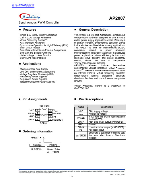
AP2007Synchronous PWM ControllerFeatures- Single 4.5V to 20V Supply Application - 0.8V + 2.0% Voltage Reference - Virtual Frequency Control TM - Fast Transient Response- Synchronous Operation for High Efficiency (93%) - Short Circuit Protect- Small Size with Minimum External Components - Soft Start and Enable Functions - Under Voltage Lockout Function - SOP-8L Pb-Free PackageApplications- Microprocessor Core Supply- Low Cost Synchronous Applications - Voltage Regulator Modules (VRM) - Networking Power Supplies - Sequenced Power Supplies- Telecommunication Power Supplies.General DescriptionThe AP2007 is a low-cost, full featured, synchronous voltage-mode controller designed for use in single ended power supply applications where efficiency is of primary concern. Synchronous operation allows for the elimination of heat sinks in many applications. The AP2007 is ideal for implementing DC/DC converters needed to power advanced microprocessors in low cost systems or in distributed power applications where efficiency is important. High-side drive circuitry, and preset shoot-thru control, allows the use of inexpensive 1P+1N-channel power switches.AP2007’s features include temperature compensated voltage reference, Virtual Frequency Control TM method to reduce external component count, an internal 200KHz virtual frequency oscillator, under-voltage lockout protection, soft-start, shutdown function and current sense comparator circuitry.Virtual Frequency Control is a trademark of PWRTEK, LLC.Pin AssignmentsSOP-8L1(Top View)VCC V REFPHASE DRVP DRVNFBGND AP20072345678SS/SHDNOrdering InformationAP2007 X X Package Packing S: SOP-8LBlank : Tube A : TapingPin DescriptionsNameDescriptionVCC Chip supply voltage V REF Reference voltagePHASEInput from the phase node betweenthe MOSFET sDRVP High side driver output (P MOSFET)GND Ground DRVN Low side driver output (N MOSFET) FB Feedback inputSS/SHDN Soft start, a capacitor to ground setsthe slow start time / Shutdownfunction查询AP2007供应商Synchronous PWM ControllerBlock DiagramCROSS CURRENT CONTROL DRVNVIRTUAL FREQ OSCILLATORDRVPR Q SQSQB R+-+-+-+-VOLTAGE REFERENCE +-VCC0.8VUNDER VOLTAGEERROR COMPVCC 12ua2ua0.2V0.9VSS/SHDNFBGNDOCSETPHASEVCCDRVPDRVNAP2007 FUNCTIONAL BLOCK DIAGRAMVirtual Frequency Control - PatentNumber 6,456,050.V REF-+0.4V -+0.4VAbsolute Maximum RatingsSymbol ParameterRange. Unit V IN VCC to GND -1 to 22 V V PHASE PHASE to GND -1 to 22 V V DRVP DRVP to GND -1 to 22 V V DRVN DRVN to GND-1 to 22 V θJC Thermal Resistance Junction to Case 90 oC/W θJA Thermal Resistance Junction to Ambient 250 oC/W T OP Operating Temperature Range -40 to +85 o C T ST Storage Temperature Range-65 to +150o C T LEADLead Temperature (Soldering) 10 Sec.300o CSynchronous PWM ControllerElectrical CharacteristicsUnless specified: V CC =12V; GND = 0V;V O = 5V; T J = 25oCSymbol Parameter Conditions Min. Typ. Max. Unit Power SupplyV CC Supply Voltage(Recommended)4.5 - 20 VI CC Supply Current DRVP & DRVN are floating - 9.5 - mA ∆V LINE Line Regulation V O = 2.5V - 0.5 % Error Comparator A OL Gain (A OL ) - 70 - dB I B Input Bias - 0.2 1 uA Oscillator F OSC Oscillator Frequency - 200 - KHz DC MAX Oscillator Max Duty Cycle 80 85 - % Mofset DriversI DRVP DRVP Source/Sink V CC – V DRVP =3VV DRVP – V GND = 2V 0.5 1 - AI DRVN DRVN Source/Sink V CC – V DRVN = 3VV DRVL – V GND = 2V0.5 1 - AV DRVL DRVP/N Low Level Voltage - - 1.2 V V DRVH DRVP/N High Level Voltage V CC -1.2- - V ProtectionT DEAD Dead Time DRVP & DRVN are floating - 150 - nS Vocset Over Current Setting Voltage 0.4 VV DRVP/N DRVP/DRVN System ErrorVoltage (Note3) V SS =Low, V CC <3.8, over current happenV CC -1.2- - VReferenceReference Voltage 0.7840.8 0.816V V REF Accuracy 0o C to 70oC-2 - + 2 %Soft StartI SSC Charge Current V SS = 1.5V 8.0 10 12 uA I SSD Discharge Current V SS = 1.5V 1.3 2 2.7 uA Under voltage lockout (UVLO)V UT Upper Threshold Voltage (V CC )- 4.0 - V V LWT Lower Threshold Voltage (V CC )- 3.8 - V V HT Hysteresis (V CC ) - 200 - mVNote 1. Specification refers to Typical Application Circuit.Note 2. This device is ESD sensitive. Use of standard ESD handling precautions is required. Note 3. Abnormal condition; Ex: over-current, under-voltage lockout, soft-start disappear.Synchronous PWM ControllerTypical Application Circuit87651234D1Option VCC SS/SHDN FB DRVP GNDPHASE DRVN Q1Q2L110uHC8470u/16V C9Vout=3.2V*+-+-C1R21KR33K ** Vout = 0.8 x (1+R3/R2)AP2007C4330nC3330nR112ΩV REF 10n470u/16V470u/16VAF9435C5AF9410C20.1uC647n C70.1u 1ΩOption 1ΩOptionR2 1K ~ 10K≅(4835)(4412)Virtual Frequency ControlVirtual Frequency Control combines the advantages of constant frequency and constant off-time control in a single mode of operation. This allows fix frequency, precision switching voltage regulator control with fast transient response and the smallest solution size. Switch duty cycle can be adjusted from 0% to 100% on a pulse by pulse basis when responding to transient conditions. Both 0% and 100% duty cycle operation can be maintained for extended periods of time in response to load or line transients. Figure 1 depicts a simplified operation of the Virtual Frequency Controltechnique: The VFC oscillator generates a pulse of a known duration (VFC_Pulse). The regulator loop responds by returning a complementary feedback pulse (FB_Pulse). The FB_Pulse duration is a result of external conditions such as inductor size, the voltage across the inductor and the duration of the VFC_Pulse. A VFC control loop is then formed whereby the duration of the VFC_Pulse is modified as a result of the FB_Pulse duration. The VFC loop arrives at a state of equilibrium, where the operating frequency remains inherently constant.GATE CONTROL LOGICVIRTUAL FREQ OSCILLATOR+-FB PulseVFC PulseVrefERROR COMPV INLout CoutVout Rfb1Rfb2Figure 1: Virtual Frequency Control Loop- Synchronous single supply application.Synchronous PWM with VFC Controller (Preliminary) Virtual Frequency Control (Continued)Virtual frequency control is a technique that provides stable, constant frequency of operation for pulse controlled architectures such as constant off-time/on-time. This is all done internal to the IC with minimal number of components and without the need for connections to external terminals such as input and/or output. No external compensation is required, thus providing a low cost, high performance fix frequency solution for switching voltage regulators.Virtual Frequency Control is a trademark of PWRTEK, LLC.Function DescriptionSynchronous Buck ConverterPrimary V CORE power is provided by a synchronous, voltage-mode pulse width modulated (PWM) controller. This section has all the features required to build a high efficiency synchronous buck converter, including soft-start, shutdown, and cycle-by-cycle current limit.Referring to the functional block diagram FIG 1, the output voltage of the synchronous converter is set and controlled by the output of the error comparator. The external resistive divider reference voltage, is derived from an internal trimmed-bandgap voltage reference. The inverting input of the error comparator receives its voltage from the FB pin.The internal oscillator uses an on-chip capacitor and trimmed precision current sources to set the virtual oscillation frequency to 200KHz. The virtual frequency oscillator sets the PWM latch. This pulls DRVN low, turning off the low-side N_MOSFET and DRVP is pulled low, turning on the high-side P-MOSFET (once the cross-current control allows it). The triangular voltage ramp at the FB pin is then compared against the reference voltage at the inverting input of the error comparator. When the FB voltage increases above the reference voltage, the comparator output goes high. This pulls DRVP high, turning off the high-side P-MOSFET, and DRVN is pulled high, turning on the low-side N-MOSFET (once the cross-current control allows it). The Virtual Frequency Oscillator then generates a programmed off time to allow the FB voltage to return to the valley voltage of the triangular ramp. At the end of the off time the PWM latch is set and the cycle repeats again.Under Voltage LockoutThe under voltage lockout circuit of the AP2007 assures that the high-side P-MOSFET driver outputs remain in the off state whenever the supply voltage drops below set parameters. Lockout occurs if V CC falls below 3.8V. Normal operation resumes once V CC rises above 4.0V. R DS(ON) Current LimitingThe current limit threshold (0.4V) is set by connecting an internal resistor from the V CC supply to OCSET. Vocset is compared to the voltage at the PHASE node. This comparison is made only when the high-side drive is high to avoid false current limit triggering due to uncontributing measurements from the MOSFET s off-voltage. When the voltage at PHASE is less than the voltage at OCSET, an over-current condition occurs and the soft start cycle is initiated. The synchronous switchturns on and SS/SHDN starts to sink 2uA. When SS/ SHDN reaches 0.2V, it then starts to source 10uA and a new cycle begins. When the soft start voltage is below 0.9V the cycle is controlled with pulse by pulse current limiting.Soft StartInitially, SS/SHDN pin sources 10uA of current to charge an external capacitor. The inverting input of the error comparator is clamped to a voltage proportional to the voltage on SS/SHDN. This limits the on-time of the high-side P-MOSFET, thus leading to a controlled ramp-up of the output voltages.Synchronous PWM with VFC Controller (Preliminary)Function Description (Continued)Hiccup ModeDuring power up, the SS/SHDN pin is internally pulled low until V CC reaches the under-voltage lockout level of 4V. Once V CC has reached 4V, the SS/SHDN pin is released and begins to source 10uA of current to the external soft-start capacitor. As the soft-start voltage rises, the inverting input of the error comparator is clamped to this voltage. When the error signal reaches the level of the internal 0.8V reference, the output voltage is to have reached its programmed voltage. If an over-current condition has not occurred the soft-start voltage will continue to rise and level off at about 2.5V.An over-current condition occurs when the high-side drive is turned on, but the PHASE node does not reach the voltage level set at the OCSET pin. Once an over-current occurs, the high-side drive is turned off and the low-side drive turns on and the SS/SHDN pin begins to sink 2uA. The soft-start voltage will begin to decrease as the 2uA of current discharge the external capacitor. When the soft-start voltage reaches 0.2V, the SS/SHDN pin will begin to source 10uA and begin to charge the external capacitor causing the soft-start voltage to rise again. If the over-current condition is no longer present, normal operation will continue. If the over-current condition is still present, the SS/SHDN pin will again begin to sink 2uA. This cycle will continue indefinitely until the over-current condition is removed.In order to prevent substrate glitching, a small-signal diode should be placed in close proximity to the chip with cathode connected to PHASE and anode connected to GND.Marking Information(Top View)SOP-8L184AP2007YY WW XLogo"02" =2002~5Synchronous PWM ControllerPackage InformationPackage Type: SOP-8LVIEW "A"LHECVIEW "A"AA 2A 1B e D7(4X)0.015x457(4X)yDimensions In Millimeters Dimensions In Inches SymbolMin. Nom. Max. Min. Nom. Max.A 1.40 1.60 1.75 0.055 0.063 0.069 A1 0.10 - 0.25 0.040 - 0.100 A2 1.30 1.45 1.50 0.051 0.057 0.059B 0.33 0.41 0.51 0.013 0.016 0.020C 0.19 0.20 0.25 0.0075 0.008 0.010D 4.80 5.05 5.30 0.189 0.199 0.209E 3.70 3.90 4.10 0.146 0.154 0.161 e - 1.27 - - 0.050 - H 5.79 5.99 6.20 0.228 0.236 0.244 L 0.38 0.71 1.27 0.015 0.028 0.050 y - - 0.10 - - 0.004θ0O - 8O 0O- 8O。
EPICF10050547NS中文资料(PCA Electronics)中文数据手册「EasyDatasheet - 矽搜」

10.0 12.0 15.0
18.0 22.0 27.0
33.0 39.0 47.0
56.0 68.0 82.0
100.0 1.5 1.8
2.2 2.7 3.3
3.9 4.7 5.6
6.8 8.2 10.0
12.0 15.0 18.0
22.0 27.0 33.0
39.0 47.0 56.0
68.0 82.0
Q
(最低)
100
8
11
8
11
8
11
8
11
8
10
8
10
8
10
8
10
8
10
8
10
8
10
8
10
8
10
8
11
8
11
8
11
8
11811来自8118
11
8
11
8
14
8
14
8
14
8
10
8
12
10
13
10
14
10
13
10
13
10
14
10
14
10
14
12
14
12
14
12
15
12
15
12
16
12
16
12
17
12
18
12
17
12
17
12
18
12
18
12
18
10
21
10
18
10
18
12
AXOS系列产品简介说明书

EMC TESTING PRODUCT OVERVIEWCUSTOMER BASE FOR EMC TESTINGCOMPACT TESTERThe AXOS is an ultra-compact immunity tester that performs all the most commonly used transient immunity tests, including Surge, EFT, Dips/Interrupts, AC/Surge Magnetic Field, Ring Wave and Telecom Surge. Full Compliance and Pre-Compliance tests are performed to meet the requirements of a wide variety of transient immunity standards, including IEC 61000-4-x “CE Mark” Basic standards, IEC 60601 for Medical equipment, and many other IEC, ANSI, ITU, UL and specific product standards.P C D 126AD E C 5D E C 6D E C 7I P 4BP A T 50 AP A T 1000Surge 1.2/50 & 8/20, 5.0kV EFT / Burst 5.0kV Dips & InterruptsSurge magnetic field 61000-4-9Insulation testing 1.2/50, 15kV 3-phase surge 32A 3-phase surge 100A 3-phase EFT/Burst 32A 3-phase EFT/Burst 100ACDNs symmetrical data & control lines CDNs asymmetrical data & control lines Capacitive coupling clampsELECTROSTATIC DISCHARGEThe ONYX simulators by HAEFELY HIPOTRONICS have been specially designed to meet all latest international standards, including IEC61000-4-2 Ed. 2 and are the most ergonomic battery and AC power operated 30kV guns on the market. 16kV and 30kV models available, along with a complete range of accessories that ensure a complete ESD test setup (verification equipment, test tables, coupling planes etc).FEATURESSTANDARDS a 16kV and 30kV models a Touch screen operation a Modulara Automatic polarity switching a Remote control software a Remote triggera Bleed-of Functionalitya Lightweight and portable design a Battery and AC operation a Environmental monitoring a Onboard LED EUT light a Smart key functionsa Contact discharge current flow detection a Self-test functiona IEC 61000-4-2 Ed. 2a IEC613402-1/-2a IEC 801-2a IEC 60571a EN 50155 a ANSI C63.16a ISO 10605a ISO 14304a ITU-T K20a MIL-STD-1512/-1514/-750D/-883a RTCA/DO-160a JEDEC 22-A114A a GR-78/1089-COREThe self test function is a built-in self test routine which checks the HV supply, the impulse capacitor, the HV discharge relays, and the insulation of the entire HV circuitry.Bleed-off functionalityThe so called bleed-off functionality of the ONYX simulator ensures via an integrated relay that the EUT is completely discharged before the next ESD pulse is initiated. This functionality ensures a maximum of test accuracy to the user without the need for a discharge brush.Smart Key OperationThe smart key button is integrated at the upper part of the discharge trigger and has various functions which are defined by the user, enabling you to run a sequence of events according to your testing requirements, and simplify test procedures.The functions include user defined discharge voltages steps, sweep voltage, On/Off LED light, Polarity Switching, control and report function.Compliance & ModularityThe design is based on the requirements of all latest international standards, including the latest IEC 61000-4-2 Ed. 2. R/C module values are available from 50-5000 Ohms and 50-1000pF , which enables users to fully test according to many international standards.Contact Discharge Current Flow Detection & Self T estThe unique NO CONTACT detection circuit function continuously monitors whether ESD pulses are discharged to the EUT , ensures users the test was successful and prevents incorrect test results.ONYX 16n16kV Electrostatic Discharge Simulatorn16kV Air & Contact Dischargen150pF/330Ω standard discharge networkn Exchangeable RC modules to meet variousstandard requirements (IEC, ISO, ANSI, MIL)n Ergonomic design and operation (touch screen) n Rechargeable battery or mains operatedn Smart key functionsn Automatic polarity switchingn Remote triggern Self test functionn Includes: Light rigid carrying case, contact and air discharge tips, mains supply, 2 x rechargeable battery pack with chargerSOFTWAREWhy should you use software to perform ESD tests?Because it makes your life easier and helps to make tests more reliable and reproducible. Benefitsn Windows XP, Windows Vista and Windows 7 compatibilityn Support of USB and optical USB interfacesn Easy-to-use and intuitive creator for test plans and test proceduresn Enhanced and highly flexible reporting capabilitiesn Up-to-date design and navigationn Intuitive operationn Independent test station n High end componentsn Very high result accuracy and precision n Higher voltage level of 7.3kV n Spike frequency up to 110 kHz n IEC/EN61000-4-4 Ed. 3n Unique windows based control and reporting software n Distinctive safety features n Ideal for over testingn Multi-test stationn Covers EFT/Burst, Surge, Dips & Interrupts, Magnetic Field, and Insulation Tests n 5.0kV EFT/Burstn Fully meets all latest standards including IEC/EN61000-4-4 Ed. 3n Ideal for pre-compliance testing and CE markingNOTE: Please refer to the COMPACT section on page 3 for details.All our EFT/Burst generators are 100% compliant to the latest standards, including IEC/EN 61000-4-4 Ed. 3, which is mandatory from April 2012.DISTINCTIVE FEATURESSTAND-ALONECOMPACTEFT/BURSTBursts or EFTs (Electrical Fast Transients) are caused by operation of electro-mechanical switches, motors and distribution switch-gear connected to the power distribution network. A typical burst consists of a large number of recurring impulses at high frequency for a short time period.V 90%50%10%FlexibilityDepending on the actual testing requirements, we offer our customers the choice between stand alone and compact testing equipment.Stand alone equipment allow users to test at levels higher than what is usually required within the standards, making such testers ideal for over-testing purposes.Compact solutions allow users to not only cover the latest eft/burst requirements, but also to carry out surge, dips & interrupts, magnetic field, and insulation tests.EFT SOLUTIONSn 5kV Burst Test Systemn Built according to IEC/EN 61000-4-4 Ed. 2 & 3 as well as to ANSI/IEEE C62.41/45 and C37.90.1n Impulse voltage up to 5kVn Frequency range from 1Hz to 1MHzn IEC, random, continuous and real burst mode n Ramp functionsn Integrated automated single-phase CDN for AC and DC up to 16A EUT mains current n Burst parameters editable during testingn 7.3kV Burst Test Systemn Built according to IEC/EN 61000-4-4 Ed. 2 & 3 as well as to ANSI/IEEE C62.41/45 and C37.90.1n Impulse voltage up to 7.3kVn Frequency range from 1Hz to 100kHzn IEC, random, continuous and real burst mode n Ramp functionsn Integrated automated single-phase CDN for AC and DC up to 16A EUT mains current n Burst parameters editable during testingAXOS SERIESPEFT 8010MANUAL 32A THREE-PHASE COUPLING-DECOUPLING NETWORK FOR EFT TESTING100A THREE-PHASE COUPLING/DECOUPLING NET-WORK FOR EFT TESTINGFP-EFT 32MFP-EFT 100M2n Built according to IEC/EN 61000-4-4 Ed. 2 & 3 and ANSI C62.41/45n Superposition of EFT impulses onto three- phase power lines and DC power lines n 8kV maximum impulse voltage n EUT voltage up to 690V/400V ACn EUT mains current up to 100A per phase n Manual coupling path switchingnSynchronization with power supply possiblen Built according to IEC/EN 61000-4-4 Ed. 2 & 3 as well as to ANSI C62.41/45n Superposition of EFT impulses onto three- phase power lines and DC power linesn 8kV maximum impulse voltagen EUT mains voltage up to 690V/400V AC, 110V DC n EUT mains current up to 32A per phase n Synchronization with power supply possible nEUT over-current protectionEFT VERIFICATION SETWAVEFORM VERIFICATION SETOPTIONSn Built according to IEC/EN 61000-4-4 Ed. 2 & 3 and ANSI C37.90.1n 40mm maximum cable size n Up to 8kV impulse voltage n Handy carrying handlen Optional transducer plate for clamp calibration/ verificationn Built according to IEC/EN 61000-4-4 Ed. 2 & 3n For verification/calibration of EFT generators (PEFT 4010, PEFT 8010, AXOS Series)n Combined 50Ω load, 54 dB attenuator n Combined 1 k Ω load, 60 dB attenuator n Required cables includedn Supplied with detailed application noten IEEE 488 interface optionn Three phase verification adaptersn Warning lamps and emergency switches n Fibre optic links (EUT fail)n Test tablesn Dedicated software WinFEAT&R n Upgrade kits for older modelsnReal burst functional extensionn Optical decoupling fibre optic links (RS232)n AC and DC adaptersn Near field test probes (E&H)n Vertical operation stands VOSSURGE - TRANSIENT / LIGHTNINGPRODUCTS AND APPLICATIONSStand-alone, compact, and modular Surge impulse generators are available up to 30kV , which cover a range of EMC surge tests including the classical IEC defined “Combination Wave“ 1.2/50 & 8/20, “Hybrid waves“ defined for telecommunications testing, 10/700, ring wave, damped oscillating wave, magnetic field, and many more.Typical standard applications include IEC, EN and ANSI for power line testing, FCC, Bellcore, ITU and ETSI for telecom testing.Our modular Surge Platform can also be used for product safety testing to UL standards and also ITE requirements. A wide range of accessories from single and three phase CDNs up to 100A and telecoms coupling units, make these systems the most modular and flexible test equipment on themarket.32A THREE-PHASE COUPLING/DECOUPLING NETWORK FOR SURGE TESTINGFP-COMB 32n Built according to IEC/EN 61000-4-5 Ed. 2 & 3n EUT voltage up to 480Vn EUT current up to 32A per phasenTest level max. 7.0kV / 3.5kA n Fully automatic test routinesn Automatic synch source switching n Test object power line bypass mode n Test object overcurrent protection15KV VOLTAGE SURGE GENERATORPS 1500n Built according to IEC/EN 60065,IEC/EN 60950-1 and UL 1414n Impulse voltage up to 15kV n Up to 24 discharges per minute n Positive and Negative Polarity n External trigger inputn Automatic selection of 4M Ω/100 M Ω parallel resistor n Impulse voltage monitor n Includes test pistol n Flash measurement n Insulation/safety testing n Component testingn Small and compact design30KV SURGE TEST SYSTEMSINGLE-PHASE COUPLING/DECOUPLING NETWORKFOR SURGE TESTING UP TO 30KV / 15KAPSURGE 30.2FP-SURGE 3010n Single-phase EUT powering n EUT mains voltage up to 480V n EUT mains current up to 10An Manual selection of coupling path and coupling capacitor n Test level up to 15kV/30kA n EUT overcurrent protection n Large integrated test cabinetn Built according to IEC/EN61000-4-5, IEC/EN 61010, IEC/EN 61643-1 and ANSI C62.41/45n Impulse voltage up to 30kV (combination wave)n Impulse current up to 30kA (8/20 µs)n Combination wave (1.2/50 µs & 8/20 µs)n 8/20 µs, 10/350 µs, 10/1000 µs current pulse n Impulse voltage & current measurement n Automatic polarity switching n Integrated test cabinetPIM 100PIM 110COMBINATION WAVE IMPULSE MODULERING WAVE IMPULSE MODULEn Built according to IEC/EN 61000-4-5 Ed. 1 & 2 and ANSI C62.41/45n 1.2/50 µs open circuit up to 7.4kV n 8/20 µs short circuit up to 3.7kAnImpulse voltage and current monitors n *1° Phase synchronizationn Reliable semiconductor HV-switchn Positive, negative and alternating polarity n Up to 12 pulses per minuten Built according to IEC/EN 61000-4-12 and ANSI C62.41/45n 100 kHz frequency, 0.5 µs rise time n Imp. voltage up to 7.8kV / 12 Ω, 30 Ω and 200 Ωn Impulse voltage and current monitors n *1° phase synchronizationn Positive, negative and alternating polarity n Up to 12 pulses per minuten Reliable semiconductor HV-switch100A THREE-PHASE COUPLING/DECOUPLING NETWORKMANUAL SURGE COUPLING UNIT FOR SYMMETRICAL DATA AND CONTROL LINESPCD 121n Built according to IEC/EN 61000-4-5 Ed. 2 Fig. 14 & Ed. 3 Fig. 10n Coupling of Combination Wave impulses n Up to 2 pairs / 4 wires can be testedn Serial resistors included, 4 x 40/80/160 Ohm n Gas arrestors and Avalanche Breakdown Diodes coupling elements included n Can be used with any surge generator n Impulse voltage up to 6.6kVnSignal Bandwidth up to > 10 MHzPCD 122MANUAL SURGE COUPLING UNIT FOR SYMMETRICAL DATA AND CONTROL LINESn Built according to IEC/EN 61000-4-5 Ed. 2 Fig. 14 & Ed. 3 Fig. 10n Coupling of 10/700 µs impulsesn Up to 2 pairs / 4 wires can be testedn Serial resistors included, 4 x 25/50/100 Ohmn Gas arrestors and Avalanche Breakdown Diodes coupling elements included n Can be used with any surge generator n Impulse voltage up to 6.6kVn Signal Bandwidth up to > 10 MHz.MANUAL SURGE COUPLING/DECOUPLING UNIT FOR DATA AND SURGE DECOUPLING UNIT FOR SYMMETRICAL DATAn Signal Bandwidth up to some 10MHzDEC 7SURGE DECOUPLING UNIT FOR ASYMMETRICAL DATA AND CONTROL LINESn Built according to:IEC/EN 61000-4-5 Ed. 2 Fig. 11, 12 & 13 & Ed. 3 Fig. 9IEC 61000-4-12:1995 Fig. 9, 10, 13 & 14 Array n Decoupling of Combination wave impulsesn Decoupling of Ring Wave (100kHz) impulsesn Up to four wire can be tested simultaneousn Decoupling: Inductors 20mH not compensatedn Protection elements are Varistors and Breakdown avalanche diodesn Can be used with any surge generatorn Impulse voltage up to 6.6kVn Signal Bandwidth up to some 100 HzLOW ENERGY IMPULSE TRANSFORMER FOR INSULATION TESTING NETWORK FOR SURGE PLATFORMPOWER FREQUENCY MAGNETIC FIELD TEST SYSTEMMAG 1000n Built according to IEC/EN 61000-4-8n 1m x 1m antenna included w/ stand n Up to 1100A/m field strength n Horizontal and Vertical testingn Continuous and short duration testing n Built in power supply at 50/60Hz n Simple interfaceMSURGE-APULSE MAGNETIC FIELD TEST SYSTEMnBuilt according to IEC/EN 61000-4-9n 8/20µs magnetic field wave shape n Up to 3000A/m field strength n Sturdy constructionn Horizontal and vertical testingn Control from HAEFEL Y surge generators n Single turn coil with 1m x 1m square area n Optional 2m x 2.6m magnetic coilDip: decrease of the mains VoltageSOFTWAREThe WinFEAT&R software is the latest generation of control and reporting software, based on a modern Drag and Drop concept. With such ease of use, even users with minimum technical experience will be carrying out tests in no time.This unique software allows users to run user specified or pre-defined tests according to the latest standards, and monitors and displays real time output current and voltage values.Communication between software and oscilloscope monitoring allows screenshots to be added to the test report.The software runs up to Windows 7 and is compatible with all stand-alone HAEFEL Y HIPOTRONICS test generators.FEATURESn Control and reporting for stand-alone EFT/Burst, Surge, Dips& Interrupts generators.n Drag and Drop applicationn User defined tests can be added and pre-defined tests arealready included (according to the standards).n Output Current/Voltage monitoring during test.n EUT supervision (max/min V/I levels).n User friendly, designed for use by users with minimumtechnical experience.n Automatic synchronization between software and PC.n Test setup uploaded to Oscilloscope.n User defined test report with oscilloscope screenshotoption.n Fully compatible with Windows 7 (32-bit/64-bit)A u g u s t 2013EuropeChinaNorth America Haefely T est AG Haefely T est AG Representative Beijing OfficeHipotronics, Inc.Birsstrasse 300 8-1-602, Fortune Street1650 Route 22 N 4052 Basel No. 67, Chaoyang Road, Chaoyang DistrictBrewster, NY 10509SwitzerlandBeijing, China 100025United States☎ + 41 61 373 4111 ☎ +86 10 8578 8099 ☎ +1 845 230 9245 + 41 61 373 4912+86 10 8578 9908 +1 845 279 2467emc-**********************************.cn*********************HAEFEL Y HIPOTRONICS has a policy of continuous product improvement. We therefore reserve the right to change design and specification without notice.OFFICES:。
夏普 MX-M550N M620N M700N数码复合机 说明书
在生产线上,扫描组件的输出功率被调至0.8 mW+10%,并且通过运行自动功率控制 (APC)使该功率保持恒定不变。 小心 使用控制装置或调节装置或者执行非此处规定的操作步骤时可能导致有害的辐射。
0-4
dragonII_copy_EX..book
Page 5 Wednesday, September 26, 2007
第1章 使用本产品前
前言 ........................................... 主要特性 ....................................... 零部件名称和功能 ............................... ● 外部 ...................................... ● 内部 ...................................... ● 操作面板 .................................. ● 触摸屏 .................................... 开关电源 ....................................... 审计模式 ....................................... ● 启用审计模式时使用本机器 .................. 1-2 1-3 1-10 1-10 1-11 1-13 1-14 1-17 1-18 1-18
dragonII_copy_EX..book
Page 2 Wednesday, September 26, 2007
1:43 PM
dragonII_copy_EX..book
Page 1 Wednesday, September 26, 2007
Alienware m15 笔记本电脑用户指南说明书

Alienware m15设置和规格计算机型号: Alienware m15管制型号: P79F管制类型: P79F001注、小心和警告注: “注”表示帮助您更好地使用该产品的重要信息。
小心: “小心”表示可能会损坏硬件或导致数据丢失,并说明如何避免此类问题。
警告: “警告”表示可能会造成财产损失、人身伤害甚至死亡。
© 2018-2019 Dell Inc. 或其子公司。
保留所有权利。
Dell、EMC 和其他商标是 Dell Inc. 或其附属机构的商标。
其他商标可能是其各自所有者的商标。
2019 - 06Rev. A03目录设置 Alienware m15 (5)创建适用于 Windows 的 USB 恢复驱动器 (6)Alienware m15 的视图 (7)右 (7)左 (7)基座 (8)显示屏 (8)背面 (9)底部 (10)Alienware m15 的规格 (11)计算机型号 (11)尺寸和重量: (11)处理器 (11)芯片组 (11)操作系统 (12)内存 (12)端口和接口 (12)通信 (13)以太网 (13)无线模块 (13)音频 (13)存储 (14)键盘 (14)摄像头 (15)触摸板 (15)触摸板手势 (15)电源适配器 (16)电池 (16)显示屏 (17)显卡 (17)计算机环境 (18)混合电源 (19)键盘快捷方式 (20)Alienware Command Center (21)3获取帮助和联系 Alienware (22)自助资源 (22)联系 Alienware (22)4设置 Alienware m15注: 根据您所订购的配置,本文档中的图像可能与您的计算机有所差异。
连接电源适配器,然后按下电源按钮。
5创建适用于 Windows 的 USB 恢复驱动器创建恢复驱动器来排除故障和修复 Windows 可能出现的问题。
创建恢复驱动器时需要一个最小容量为 16 GB 的空 USB 闪存驱动器。
英特尔外星人M15设备设置和规格说明书

Alienware m15Setup and Specifications Computer Model: Alienware m15Regulatory Model: P79FRegulatory Type: P79F001Notes, cautions, and warningsNOTE: A NOTE indicates important information that helps you make better use of your product.CAUTION: A CAUTION indicates either potential damage to hardware or loss of data and tells you how to avoid the problem.WARNING: A WARNING indicates a potential for property damage, personal injury, or death.© 2018-2019 Dell Inc. or its subsidiaries. All rights reserved. Dell, EMC, and other trademarks are trademarks of Dell Inc. or its subsidiaries. Other trademarks may be trademarks of their respective owners.2019 - 03Rev. A02ContentsSet up your Alienware m15 (5)Create a USB recovery drive for Windows (6)Views of Alienware m15 (7)Right (7)Left (7)Base (8)Display (8)Back (9)Bottom (10)Specifications of Alienware m15 (11)Computer model (11)Dimensions and weight (11)Processors (11)Chipset (11)Operating system (12)Memory (12)Ports and connectors (12)Communications (13)Ethernet (13)Wireless module (13)Audio (13)Storage (14)Keyboard (14)Camera (15)Touchpad (15)Touchpad gestures (15)Power adapter (16)Battery (16)Display (17)Video (17)Computer environment (18)Hybrid power (19)Keyboard shortcuts (20)Alienware Command Center (21)3Getting help and contacting Alienware (22)Self-help resources (22)Contacting Alienware (22)4Set up your Alienware m15NOTE: The images in this document may differ from your computer depending on the configuration you ordered.1 Connect the power adapter and press the power button.2 Create recovery drive for Windows.NOTE: It is recommended to create a recovery drive to troubleshoot and fix problems that may occur withWindows.For more information, see Create a USB recovery drive for Windows.5Create a USB recovery drive for WindowsCreate a recovery drive to troubleshoot and fix problems that may occur with Windows. An empty USB flash drive with a minimum capacity of 16 GB is required to create the recovery drive.NOTE: This process may take up to an hour to complete.NOTE: The following steps may vary depending on the version of Windows installed. Refer to the Microsoft support site for latest instructions.1 Connect the USB flash drive to your computer.2 In Windows search, type Recovery.3 In the search results, click Create a recovery drive.The User Account Control window is displayed.4 Click Y es to continue.The Recovery Drive window is displayed.5 Select Back up system files to the recovery drive and click Next.6 Select the USB flash drive and click Next.A message appears, indicating that all data in the USB flash drive will be deleted.7 Click Create.8 Click Finish.For more information about reinstalling Windows using the USB recovery drive, see the Troubleshooting section of your product's Service Manual at /support/manuals.6Views of Alienware m15Right1USB 3.1 Gen 1 ports (2)Connect peripherals such as external storage devices and printers. Provides data transfer speeds up to 5 Gbps.Left1Security-cable slot (for Noble locks)Connect a security cable to prevent unauthorized movement of your computer.2Network portConnect an Ethernet (RJ45) cable from a router or a broadband modem for network or Internet access.3USB 3.1 Gen 1 port with PowerShareConnect peripherals such as external storage devices and printers.Provides data transfer speeds up to 5 Gbps. PowerShare enables you to charge your USB devices even when yourcomputer is turned off.NOTE: If your computer is turned off or in hibernate state, you must connect the power adapter to charge your devices using the PowerShare port. Y ou must enable this feature in the BIOS setup program.NOTE: Certain USB devices may not charge when the computer is turned off or in sleep state. In such cases,turn on the computer to charge the device.4Headset portConnect headphones or a headset (headphone and microphone combo).7Base1Power button (Alienhead)Press to turn on the computer if it is turned off, in sleep state, or in hibernate state.Press to put the computer in sleep state if it is turned on.Press and hold for 4 seconds to force shut-down the computer.NOTE: Y ou can customize the power-button behavior in Power Options.2Right-click areaPress to right-click.3Left-click areaPress to left-click.4TouchpadMove your finger on the touchpad to move the mouse pointer. Tap to left-click and two finger tap to right-click. Display81Left microphoneProvides digital sound input for audio recording and voice calls.2CameraEnables you to video chat, capture photos, and record videos.3Camera-status lightTurns on when the camera is in use.4Right microphoneProvides digital sound input for audio recording and voice calls.Back1HDMI portConnect to a TV or another HDMI-in enabled device. Provides video and audio output.2Mini DisplayPortConnect to a TV or another DisplayPort-in enabled device. Provides video and audio output.3Thunderbolt 3 (USB Type-C) portSupports USB 3.1 Gen 2, DisplayPort 1.2, Thunderbolt 3 and also enables you to connect to an external display using a display adapter.Provides data transfer rates up to 10 Gbps for USB 3.1 Gen 2 and up to 40 Gbps for Thunderbolt 3.NOTE: A USB Type-C to DisplayPort adapter (sold separately) is required to connect a DisplayPort device.4External graphics portConnect an Alienware Graphics Amplifier to enhance the graphics performance.5Power-adapter portConnect a power adapter to provide power to your computer and charge the battery.9Bottom1Right speakerProvides audio output.2Service Tag labelThe Service Tag is a unique alphanumeric identifier that enables Dell service technicians to identify the hardware components in your computer and access warranty information.3Left speakerProvides audio output.10Specifications of Alienware m15 Computer modelAlienware m15Dimensions and weightTable 1. Dimensions and weightProcessorsTable 2. Processor specificationsChipsetTable 3. Chipset specificationsOperating system•Windows 10 Home (64-bit)•Windows 10 Professional (64-bit) MemoryTable 4. Memory specificationsPorts and connectorsTable 5. External ports and connectors specificationsTable 7. Internal ports and connectors specificationsCommunicationsEthernetTable 8. Ethernet specificationsWireless moduleTable 9. Wireless module specificationsAudioTable 10. Audio specificationsStorageY our computer supports one of the following configurations:•One 2.5-inch hard drives•One M.2 PCIe solid-state drive•One M.2 PCIe solid-state drive and one 2.5-inch hard drive•One M.2 Intel Optane and one 2.5-inch hard drive•Two M.2 PCIe solid-state drivesNOTE: The primary drive of your computer varies depending on the storage configuration. For computers:•with a M.2 drive, the M.2 drive is the primary drive.•without M.2 drive, the 2.5-inch drive is the primary drive.Table 11. Storage specificationsKeyboardTable 12. Keyboard specificationsCameraTable 13. Camera specificationsTouchpadTable 14. Touchpad specificationsTouchpad gesturesFor more information about touchpad gestures for Windows 10, see the Microsoft knowledge base article 4027871 at .Power adapterTable 15. Power adapter specificationsNOTE: Alienware m15 supports Hybrid power feature during heavy loading. For more information, see Hybrid power.BatteryTable 16. Battery specificationsNOTE: Alienware m15 supports Hybrid power feature during heavy loading. For more information, see Hybrid power.DisplayTable 17. Display specificationsVideoTable 18. Discrete graphics specificationsTable 19. Integrated graphics specificationsComputer environmentAirborne contaminant level: G1 as defined by ISA-S71.04-1985 Table 20. Computer environment* Measured using a random vibration spectrum that simulates user environment.† Measured using a 2 ms half-sine pulse when the hard drive is in use.‡ Measured using a 2 ms half-sine pulse when the hard-drive head is in parked position.Hybrid powerThe Hybrid power feature enables your computer to function optimally during the following instances of heavy loading. Examples of heavy loading include:•Graphics and processor-intensive applications and/or gaming•External power loading from devices relying on your computer as a power source such as gaming mice, keyboards, external speakers, and headsetsWhen during instances of heavy loading, system performance is maintained through hybrid power. Hybrid power coordinates the power drawn from the power adapter and battery, allowing power to be drawn from the battery for up to five percent per hour with the power adapter plugged in. This feature is disabled when the battery falls below 20 percent charge.The following table shows the different scenarios and benefits of hybrid power:Table 21. Hybrid power feature descriptionKeyboard shortcutsNOTE: Keyboard characters may differ depending on the keyboard language configuration. Keys used for shortcuts remain the same across all language configurations.NOTE: Y ou can define the primary behavior of the function keys (F1–F12) by changing Function Key Behavior in BIOS setup program.Table 22. List of keyboard shortcutsTable 23. List of Macro keysAlienware Command CenterAlienware Command Center (AWCC) provides a single interface to customize and enhance the gaming experience. The AWCC dashboard displays most recently played or added games, and provides game-specific information, themes, profiles, and access to computer settings. Y ou can quickly access settings such as game-specific profiles and themes, lighting, macros, and audio that are critical to the gaming experience.AWCC also supports AlienFX 2.0. AlienFX enables you to create, assign, and share game-specific lighting maps to enhance the gaming experience. It also enables you to create your own individual lighting effects and apply them to the computer or attached peripherals. AWCC embeds Peripheral Controls to ensure a unified experience and the ability to link these settings to your computer or game.AWCC supports the following features:•FX: Create and manage the AlienFX zones.•Fusion: Includes the ability to adjust game-specific Power Management, Sound Management, and Thermal Management features.•Peripheral Management: Enables peripherals to appear in and be managed in Alienware Command Center. Supports key peripheral settings and associates with other functions such as profiles, macros, AlienFX, and game library.AWCC also supports Sound Management, Thermal Controls, CPU, GPU, Memory (RAM) monitoring. For more information about AWCC, see the Alienware Command Center Online Help.21Getting help and contacting AlienwareSelf-help resourcesY ou can get information and help on Alienware products and services using these online self-help resources: Table 24. Alienware products and online self-help resourcesIn Windows search, typeContacting AlienwareTo contact Alienware for sales, technical support, or customer service issues, see .NOTE: Availability varies by country/region and product, and some services may not be available in your country/ region.NOTE: If you do not have an active Internet connection, you can find contact information about your purchase invoice, packing slip, bill, or Dell product catalog.22。
M150XN07_07中文资料
M150XN07 V.2Product SpecificationAU OPTRONICS CORPORATIONProduct Specification15.0” XGA Color TFT-LCD ModuleModel Name: M150XN07 V.2Approved by Prepared byCC Chiu TC TsaiDDBU Marketing Division / AU Optronics corporationCustomer Checked & Approved byProduct Specification15.0” XGA Color TFT-LCD ModuleModel Name: M150XN07V.2 (u) Preliminary Specifications( ) Final Specifications Note: This Specification is subject to change without notice.Contents1.0 Handling Precautions (5)2.0 General Description (6)2.1 Display Characteristics (6)2.2 Optical Characteristics (7)3.0 Functional Block Diagram (12)4.0 Absolute Maximum Ratings (13)4.1 TFT LCD Module (13)4.2 Backlight Unit (13)4.3 Absolute Ratings of Environment (13)5.0 Electrical characteristics (14)5.1 TFT LCD Module (14)5.1.1 Power Specification (14)5.1.2 Signal Electrical Characteristics (15)5.2 Backlight Unit (16)6.0 Signal Characteristic (17)6.1 Pixel Format Image (17)6.2 The input data format (18)6.3 Signal Description (19)6.4 Interface Timing (20)6.4.1 Timing Characteristics (20)6.4.2 Timing diagram (21)6.5 Power ON/OFF Sequence (22)7.0 Connector & Pin Assignment (23)7.1 TFT LCD Module (23)7.2 Backlight Unit (24)7.3 Signal for Lamp connector (24)8.0 Reliability (25)9.0 Safety (26)9.1 Sharp Edge Requirements (26)9.2 Materials (26)9.2.1 Toxicity (26)9.2.2 Flammability (26)9.3 Capacitors (26)10.0 Other requirement (26)10.1 National Test Lab Requirement (26)10.2 Label (26)11.0 Mechanical Characteristics (27)Record of RevisionVersion and Date Page Old description New Description Remark 0.1 2005/02/14 All First Edition for Customer1.0 Handling Precautions1) Since front polarizer is easily damaged, pay attention not to scratch it.2) Be sure to turn off power supply when inserting or disconnecting from input connector.3) Wipe off water drop immediately. Long contact with water may cause discoloration or spots.4) When the panel surface is soiled, wipe it with absorbent cotton or other soft cloth.5) Since the panel is made of glass, it may break or crack if dropped or bumped on hard surface.6) Since CMOS LSI is used in this module, take care of static electricity and insure human earth whenhandling.7) Do not open nor modify the Module Assembly.8) Do not press or pat the panel surface by fingers,hand or tooling.9) Do not press the reflector sheet at the back of the module to any directions.10) In case if a module has to be put back into the packing container slot after once it was taken out from thecontainer, do not press the center of the CCFL reflector edge. Instead, press at the far ends of the CCFL reflector edge softly. Otherwise the TFT module may be damaged.11) At the insertion or removal of the Signal Interface Connector, be sure not to rotate nor tilt the InterfaceConnector of the TFT module.12) After installation of the TFT module into an enclosure (Desktop monitor Bezel, for example), do not twistnor bend the TFT Module even momentary. At designing the enclosure, it should be taken into consideration that no bending/twisting forces are applied to the TFT module from outside. Otherwise the TFT module may be damaged.2.0 General DescriptionThis specification applies to the 15.0 inch Color TFT/LCD Module M150XN07 V2.This module is designed for a display unit of personal computer.The display supports the XGA (1024 (H) x 768(V)) screen format and 16.2M colors (RGB 6-bits + FRC data). All input signals are 1 Channel LVDS interface compatible.This module does not contain an inverter card for backlight.2.1 Display CharacteristicsThe following items are characteristics summary on the table under 25 ℃condition:ITEMS Unit SPECIFICATIONSScreen Diagonal [mm] 381 (15”)Active Area [mm] 304.128 (H) x 228.096Pixels H x V 1024(x3) x 768Pixel Pitch [mm] 0.297 (per one triad) x 0.297Pixel Arrangement R.G.B. Vertical StripeDisplay Mode TN mode, Normally WhiteWhite Luminance [cd/m2] 250 (Typ) @ 8mAContrast Ratio 500 : 1 (Typ)Optical Rise Time/Fall Time [msec] 12 (Typ) (Note 1) Color Saturation 65% NTSCNominal Input Voltage VDD [Volt] +3.3 VPower Consumption(VDD line + CCFL line)[Watt] 13.3 W (Typ.) @8mA (All Black Pattern)Weight [Grams] 1100 (Typ)Min. Typ. Max.Horizatal(H) 326.0 326.5 327.0Vertical(V) 253.0 253.5 254.0Physical Size [mm]Depth(D) - - 12.0Electrical Interface 1 Channel LVDSSupport Color 16.2M colors (RGB 6-bit + FRC data)Temperature RangeOperating Storage (Shipping) [o C][o C]0 to +50-20 to +60Surface Treatment Hard-coating (3H), anti-glare treatment Note 1 :System should warm up for at least one hourmeasuring distance2.2 Optical CharacteristicsThe optical characteristics are measured under stable conditions at 25℃ (Room Temperature):Item Unit Conditions Min. Typ. Max.Note Horizontal (Right) CR = 10 (Left) TBD6565- Vertical (Up) CR = 10 (Down) TBD65 55keep total 120(Mayb e 60,60)Horizontal (Right) CR = 5 (Left) TBD TBD Viewing Angle [degree]Vertical (Up) CR = 5 (Down)TBD TBD Contrast ratioNormal Direction TBD 500 -Rising Time - TBD TBD Falling Time - TBD TBD Response Time[msec]Rising + Falling - 12 Note 1Red x 0.61 0.64 0.67 Red y0.30 0.33 0.36 Green x 0.27 0.30 0.33 Green y 0.56 0.59 0.62 Blue x 0.12 0.15 0.18 Color / Chromaticity Coordinates (CIE)Blue y0.07 0.10 0.13 White x 0.28 0.31 0.34 Color Coordinates(CIE)WhiteWhite y 0.30 0.33 0.36 White Luminance @ CCFL 8mA (center)[cd/m 2] 200 250 - Luminance Uniformity [%] 75 80 Note 2 Crosstalk (in 75Hz) [%] 1.2 1.5 Note 3 FlickerdB-20Note 4 Equipment Pattern Generator, Power Supply, Digital Voltmeter, Luminance meter (PR 880, BM-5A ,BM 7 ,CS-1000, CA210, SR_3 & EZ Contrast(ELDIM)* )Aperture1∘with 50cm viewing distanceTest Point Center (VESA point 9) Environment < 1 lux*’ EZ Contrast is different measurement tool with very close viewing distance.Note 1: Definition of Response timeThe output signals of photo detector are measured when the input signals are changed from “Black” to “White”(rising time), and from “White” to “Black ”(falling time), respectively. The response time is interval between the 10% and 90% of amplitudes.Note 2: Brightness uniformity of these 9 points is defined as below50 %90 % 90 % 50 %10 %10 %Note 3: Crosstalk is defined as below :Unit: percentage of dimension of display areal L A -L A ’ l / L A x 100%= 1.5% max., L A and L Bl L B -L B ’ l / L B x 100%= 1.5% max., L A ’ and L B ’ are brightness at location A ’ and B ’Note 4: Test Paterm: Subchecker Pattern at 127 gray levelR G B R G BR G B R G B R G B R G B1/2 1/21/61/61/2 1/21/61/6 2/3 1/3 1/3 2/3Gray Level = L127Gray Level = L0Time3.0 Functional Block DiagramThe following diagram shows the functional block of the 15.0 inches wide Color TFT/LCD Module:CWY20G – A0G16 / MSB240420 JST-BHR-03VS-1Mating Type : HRS DF14-20S-1.25C SM02(8.0)B-BHS-1-TB4.0 Absolute Maximum RatingsAbsolute maximum ratings of the module is as following:4.1 TFT LCD ModuleItem Symbol Min Max Unit Conditions Logic/LCD Drive VDD 0.3 +3.6 [Volt] Note 1,24.2 Backlight UnitItem Symbol Min Max Unit Conditions CCFL Current IRCFL - 8.5 [mA] rms Note 1,24.3 Absolute Ratings of EnvironmentItem Symbol Min Max Unit Conditions Operating Temperature TOP 0 +50 [o C] Note 3 Operating Humidity HOP 8 90 [%RH] Note 3 Storage Temperature TST -20 +60 [o C] Note 3 Storage Humidity HST 8 90 [%RH] Note 3Note 1: With in Ta (25℃)Note 2: Permanent damage to the device may occur if exceed maximum valuesNote 3:For quality perfermance, please refer to AUO IIS(Incoming Inspection Standard). Please refer the graph below for the corresponding of temperature and humidity."5.0 Electrical characteristics5.1 TFT LCD Module 5.1.1 Power SpecificationInput power specifications are as follows;Symbol Parameter Min Typ Max Units ConditionVDD Logic/LCD Drive Voltage 3.0 3.3 3.6 [Volt] ±10%IDD VDD current - 600 700 [mA] Vin=3.3V , Gray Bar Pattern, at 60HzIrush LCD Inrush Current - - 3 [A] NotePDD VDD Power 2.0 2.3 [Watt] Vin=3.3V , Gray Bar Pattern, at 60HzVDDrpAllowableLogic/LCD Drive Ripple Voltage100[mV] p-pVin=3.3V , All Black Pattern, at 75HzNote: Measurement conditions:SWVin rising time0V3.3V5.1.2 Signal Electrical CharacteristicsInput signals shall be low or Hi-Z state when Vin is offIt is recommended to refer the specifications of SN75LVDS82DGG (Texas Instruments) in detail.Each signal characteristics are as follows;Symbol Parameter Min Typ Max Units ConditionVTH Differential Input High Threshold - - 100 [mV] VICM = 1.2V NoteVTL Differential Input Low Threshold -100 -- [mV] VICM = 1.2V Note │VID │ Input DifferentialVoltage100 400 600 [mV] Note VICMDifferential Input Common ModeVoltage1.1-1.45[V]VTH/VTL = ± 100mV NoteNote: LVDS Signal Waveform5.2 Backlight UnitParameter guideline for CCFL InverterSymbol Parameter Min.Typ.Max.Unit ConditionIRCFL CCFL operation range 2.5 8 8.5 [mA]rms(Ta=25o C)Note 4ICFL CCFL Inrush current - - 20 [mA]FCFL CCFL Frequency 40 55 80 [KHz] (Ta=25o C) Note 1ViCFL(0o C) (reference) CCFL Ignition Voltage1450 - -[Volt]rms(T a=0o C) Note 3ViCF (25o C) (reference) CCFL Ignition Voltage1100 - -[Volt]rms(Ta=25o C) Note 3VCFL CCFL Discharge Voltage-620(@8mA)710(@2.5mA)[Volt]rms(Ta=25o C) Note 2PCFL CCFL Power consumption@8mA(excluding inverter)- 10 11 [Watt] (Ta=25o C) Note 2Note 1: CCFL frequency should be carefully determined to avoid interference between inverter and TFT LCD.Note 2: Calculator value for reference (IRCFLxVCFLx2=PCFL).Note 3: CCFL inverter should be able to give output a voltage more than 1450 volt. Lamp units need 1450 volt minimum for ignition.Note 4: CCFL life time is 30,000hr at 8.0mA, it’s defined as when the brightness is reduced by half. It’s recommended not to exceed 8.0mA for CCFL life time concern and it’s prohibited to exceed 8.5mA for safety concern.6.0 Signal Characteristic6.1 Pixel Format ImageFollowing figure shows the relationship of the input signals and LCD pixel format.6.2 The input data formatDE VS HS OG0OR5OR4OR3OR2OR1OR0OB0OG3OG4OG1OG2OB1OG5OB5OB3OB4OB2OR7OB7OR6OB6OG7OG6CLKIN+RIN0 +/-CLKIN-Rsvd Current CycleRIN1 +/-RIN2 +/-RIN3 +/-Note1: Please follow PSWG. Note2: 8-bit inNote3: R/G/B data 7:MSB, R/G/B data 0:LSB6.3 Signal DescriptionThe module using a pair of LVDS receiver SN75LVDS82(Texas Instruments) or compatible. LVDS is a differential signal technology for LCD interface and high speed data transfer device. Transmitter shall be SN75LVDS83(negative edge sampling) or compatible. The first LVDS port(RxOxxx) transmits odd pixels while the second LVDSport(RxExxx) transmits even pixels.CWY20G-A0D1T (PTWO) or MSB240420 (STM)Pin No. Symbol Description1 VDD Power Supply, 3.3V (typical)2 VDD Power Supply, 3.3V (typical)3 VSS Ground4 VSS Ground5 Rin0-- LVDS differential data input (R0-R5, G0)6 Rin0++ LVDS differential data input (R0-R5, G0)7 VSS Ground8 Rin1-- LVDS differential data input (G1-G5, B0-B1)9 Rin1++ LVDS differential data input (G1-G5, B0-B1)10 VSS Ground11 Rin2-- LVDS differential data input (B2-B5, HS, VS, DE)12 Rin2++ LVDS differential data input (B2-B5, HS, VS, DE)13 VSS Ground14 ClkIN-- LVDS differential clock input15 ClkIN++ LVDS differential clock input16 VSS Ground17 Rin3-- LVDS differential data input (R6-R7, G6-G7,B6-B7)18 Rin3+- LVDS differential data input (R6-R7, G6-G7,B6-B7)19 VSS Ground20 VSS GroundNote: Please follow PSWG.6.4 Interface Timing6.4.1 Timing CharacteristicsBasically, interface timings described here is not actual input timing of LCD module but output timing of SN75LVDS82DGG (Texas Instruments) or equivalent.Signal Parameter Symbol MIN TYP MAX Unit Clock Timing Clock frequency clk 50 65 81 MHz Hsync TimingHorizontal active Thd 1024 1024 1024 TclkHorizontal blanking Thbl 40 320 400 TclkHorizontal period Th 1064 1344 1424 Tck Vsync TimingVertical active Tvd 768 768 768 ThVertical blanking Tvbl 8 38 75 ThVertical period Tv 776 806 843 ThNote:DE mode onlyNote: Typical value refer to VESA STANDARD6.4.2 Timing diagram6.5 Power ON/OFF SequenceVin power and lamp on/off sequence is as follows. Interface signals are also shown in the chart. Signals from any system shall be Hi-Z state or low level when Vin is off.On7.0 Connector & Pin AssignmentPhysical interface is described as for the connector on module.These connectors are capable of accommodating the following signals and will be following components.7.1 TFT LCD ModuleConnector Name / Designation Interface Connector / Interface card Manufacturer P-TWO or compatibleType Part Number CWY20G – A0G16 / MSB240420Mating Housing Part Number HRS DF14-20S-1.25CPin#Signal Name Pin#Signal Name1 VDD2 VDD3 VSS4 VSS5 Rin0-6 Rin0+7 VSS8 Rin1-9 Rin1+10 VSS11 Rin2-12 Rin2+13 VSS14 ClkIN-15 ClkIN+16 VSS17 Rin3-18 Rin3+19 VSS20 VSS7.2 Backlight UnitConnector Name / Designation For Lamp ConnectorManufacturer JST or compatibleType / Part Number BHR-03VS-1Mating Type / Part Number SM02(8.0)B-BHS-1-TB 7.3 Signal for Lamp connectorPin Symbol Description1 HV Lamp High Voltage2 NC No connection3 LV Groundu Cable length: 140 +- 5 mmu Connector-output position: right side (front view)u Lamp assembly design shall be easy for replacement and repair.8.0 ReliabilityReliability test conditionNo Test Item Test Condition1 Temperature Humidity Bias (THB) 50℃, 80%, 300hours2 High Temperature Operation (HTO) 50℃, 300hours3 Low Temperature Operation (LTO) 0℃, 300hours4 High Temperature Storage (HTS) 60℃, 300hours5 Low Temperature Storage (LTS) -20℃, 300hours6 Thermal Shock Test (TST) -20℃/30min, 60℃/30min, 100 cycles7 On/Off Test On/10sec, Off/10sec, 30,000 cycles8 Shock Test (Non-Operating) 50G, 20ms, Half-sine wave (+ X, +Y, +Z)9 Vibration Test (Non-Operating) 1.5G(10~200Hz P- P), 30 Minutes each Axis (X, Y, Z)10 ESD (ElectroStatic Discharge) Contact Discharge: ± 8KV, 150pF(330Ω ) 1sec, 8 points, 25 times/ pointAir Discharge: ± 15KV, 150pF(330Ω ) 1sec, 8 points, 25 times/ point11 Altitude Test Operation:10,000 ftNon-Operation:30,000 ft12 Drop Test The drop height is 60cm9.0 Safety9.1 Sharp Edge RequirementsThere will be no sharp edges or comers on the display assembly that could cause injury.9.2 Materials9.2.1 ToxicityThere will be no carcinogenic materials used anywhere in the display module. If toxic materialsare used, they will be reviewed and approved by the responsible AUO Toxicologist.9.2.2 FlammabilityAll components including electrical components that do not meet the flammability gradeUL94-V1 in the module will complete the flammability rating exception approval process.The printed circuit board will be made from material rated 94-V1 or better. The actual ULflammability rating will be printed on the printed circuit board.9.3 CapacitorsIf any polarized capacitors are used in the display assembly, provisions will be made to keepthem from being inserted backwards.10.0 Other requirement10.1 National Test Lab RequirementThe display module will satisfy all requirements for compliance toUL 1950, First Edition U.S.A. Information Technology EquipmentCSA C22.2 No.950-M89 Canada, Information Technology EquipmentEEC 950 International, Information Technology EquipmentEN 60 950 International, Information Processing Equipment(European Norm for IEC950)10.2 LabelThe label is on the panel as shown below:。
XN0150100L资料

0 to 0.1
■ Absolute Maximum Ratings Ta = 25°C
4: Emitter 5: Base (Tr1) Mini5-G1 Package
Marking Symbol: 5R Internal Connection
3 4 5
1.1+0.3 –0.1
Tr1
2
1
■ Electrical Characteristics Ta = 25°C ± 3°C
Base-emitter voltage VBE (V)
Collector current IC (mA)
hFE IC
600 VCE = 10 V
300
fT I E
VCB = 10 V Ta = 25°C 240
NV IC
VCE = 10 V GV = 80 dB 200 Function = FLAT Ta = 25°C
Large)
Conditions IC = 10 µA, IE = 0 IC = 2 mA, IB = 0 IE = 10 µA, IC = 0 VCB = 20 V, IE = 0 VCE = 10 V, IB = 0 VCE = 10 V, IC = 2 mA VCE = 10 V, IC = 2 mA IC = 100 mA, IB = 10 mA VCB = 10 V, IE = −2 mA, f = 200 MHz VCB = 10 V, IE = 0, f = 1 MHz
XN01501
PT Ta
500
60
IC VCE
240
Ta = 25°C IB = 160 µA
IC I B
VCE = 10 V Ta = 25°C 200
- 1、下载文档前请自行甄别文档内容的完整性,平台不提供额外的编辑、内容补充、找答案等附加服务。
- 2、"仅部分预览"的文档,不可在线预览部分如存在完整性等问题,可反馈申请退款(可完整预览的文档不适用该条件!)。
- 3、如文档侵犯您的权益,请联系客服反馈,我们会尽快为您处理(人工客服工作时间:9:00-18:30)。
AU OPTRONICS CORPORATIONProduct Specifications15.0” XGA Color TFT-LCD ModuleModel Name: M150XN07V.1Approved by Prepared byDDBU Marketing Division / AU Optronics CroporationCustomerChecked & Approved bySpec. No.: DDPM-M150XN07-0.1 Version: 1 Total pages: 26 Date: 2003-July-31Product Specifications15.0” XGA Color TFT-LCD ModuleModel Name:M150XN07V.1 (u) Preliminary Specifications () Final Specificationsi Contents1.0 Handling Precautions2.0 General Description2.1 Display Characteristics2.2 Functional Block Diagram3.0 Absolute Maximum Ratings4.0 Optical Characteristics4.1 Signal for Lamp connector4.2 Parameter guideline for CCFL Inverter5.0 Signal Interface5.1 Module Interface Connectors5.2 Module Connector Pin Configuration5.3 Backlight Connectors5.4 Backlight Connector Pin Configuration5.5 Signal Electrical Characteristics5.6 Interface Timings Characteristics5.7 Interface Timing Definition6.0 Pixel format image7.0 Power Consumption8.0 Power ON/OFF Sequence9.0 Backlight Characteristics9.1 Signal for Lamp connector9.2 Parameter guideline for CCFL Inverter10.0Vibration, Shock, and Drop10.1 Vibration & Shock10.1.1 Vibration Test Spec10.1.2 Shock Test Spec10.2 Drop11.0 Environment11.1 Temperature and Humidity11.1.1 Operating Conditions11.1.2 Shipping Conditions11.2 Atmospheric Pressure11.3 Thermal Shock12.0 Reliability12.1 Failure criteria12.2 Failure rate12.2.1 Usage12.2.2 Components de-rating12.3 CCFL life12.4 ON/OFF cycle13.0 Safety13.1 Sharp edge requirement13.2 Material13.2.1 Toxicity13.2.2 Flammability13.3 Capacitors13.4 Hazardous voltage14.0 Other requirements14.1 Smoke free design14.2 National test lab requirement15.0 Label16.0 Mechanical Characteristicsii Record of RevisionVersion and Date Page Old description New Description Remark 0.1 2003/06/10 All First Edition for Customer All1.0 Handling Precautions1) Since front polarizer is easily damaged, pay attention not to scratch it.2) Be sure to turn off power supply when inserting or disconnecting from input connector.3) Wipe off water drop immediately. Long contact with water may cause discoloration or spots.4) When the panel surface is soiled, wipe it with absorbent cotton or other soft cloth.5) Since the panel is made of glass, it may break or crack if dropped or bumped on hard surface.6) Since CMOS LSI is used in this module, take care of static electricity and insure human earth whenhandling.7) Do not open nor modify the Module Assembly.8) Do not press the reflector sheet at the back of the module to any directions.9) In case if a Module has to be put back into the packing container slot after once it was taken out from thecontainer, do not press the center of the CCFL Reflector edge. Instead, press at the far ends of the CFL Reflector edge softly. Otherwise the TFT Module may be damaged.10) At the insertion or removal of the Signal Interface Connector, be sure not to rotate nor tilt the InterfaceConnector of the TFT Module.11) After installation of the TFT Module into an enclosure (LCD monitor housing, for example), do not twist norbend the TFT Module even momentary. At designing the enclosure, it should be taken into consideration that no bending/twisting forces are applied to the TFT Module from outside. Otherwise the TFT Module may be damaged.12) Cold cathode fluorescent lamp in LCD contains a small amount of mercury. Please follow local ordinances orregulations for disposal.13) Small amount of materials having no flammability grade is used in the LCD module. The LCD module should besupplied by power complied with requirements of Limited Power Source (2.11, IEC60950 or UL1950), or be applied exemption.14) The LCD module is designed so that the CFL in it is supplied by Limited Current Circuit (2.4, IEC60950 or UL1950).Do not connect the CFL in Hazardous Voltage Circuit.2.0 General DescriptionThis specification applies to the 15.0 inch Color TFT-LCD Module M150XN07.The display supports the XGA (1024(H) x 768(V)) screen format and 262,144 colors (RGB 6-bits data). All input signals are 1 Channel LVDS interface compatible.This module does not contain an inverter card for backlight.Features-XGA 1024(H) x 768(V) resolution-2 CCFLs (Cold cathode Fluorescent Lamp)-High contrast ratio, high aperture ratio-Wide viewing angle-High-speed response-Low power consumptionApplicationDesktop monitors2.1 Display CharacteristicsThe following items are characteristics summary on the table under 25 ℃condition:ITEMS Unit SPECIFICATIONSScreen diagonal [mm] 381 (15”)Outline dimension [mm] 326.5 x 253.5 x 12.0 typ.Display Area [mm] 304.128 (H) x 228.096(38.1cm diagonal)Resolution 1024(R,G,B x 3) x 768Pixel Pitch [mm] 0.297 x 0.297Pixel Arrangement R.G.B. Vertical StripeDisplay Mode TN mode, Normally WhiteTypical white Luminance. [cd/m2] 250nit (typ) @8mA (note 1)Brightness uniformity 80% typ. (note 2)Luminance uniformity 1.7 max.(Note 3)Crosstalk (at 60Hz) 1.2% max. (note 4)Contrast Ratio 400 : 1 typ.Support Colors 262,144 colors (6-bit for R,G,B)Chromaticity(CIE1931)White-x 0.313White-y 0.329Color Gamut 60% typ., of NTSC coverageViewing angle 60(left),60(right),40(up),60(down) CR=10 Response Time [msec] 16ms typ. (Tr +Tf)Nominal Input Voltage VDD [Volt] +3.3 VPower Consumption(VDD line + CCFL line)[Watt] 15 (typ.) @8mA (All Black Pattern)Electrical Interface LVDS (1 ch)Frame rate [Hz] 60Hz typ., 75Hz max.Weight [Grams] 1100 typ.Mounting method Side mountingSurface treatment Anti-glare, hard coating (3H)Temperature RangeOperating Storage (Shipping) [o C][o C]0 to +50-20 to +60Note 1: Brightness is measured at the center point of brightness value with all pixels displaying white.Note 2: Brightness uniformity of these 9 points is defined as below:(Min. brightness / Max. brightness) x 100%Note 3: TCO ’99 Certification Requirements and test methods for environmental labeling of Display Report No. 2defines Luminance uniformity as below:((Lmax,+30deg. / Lmin,+30deg.) + (Lmax,-30deg. / Lmin,-30deg.)) / 2256512192384576Unit: pixels76850 %90 % 90 %50 %10 %Unit: percentage of dimension of display area10 %TCO 99 certification requirements and test methods:Effective area :W ×H2) D is the diagonal of the screen in centimeters. And m d is as follow.md (cm)=D ×1.5 with a minimum distance :m d =50 cm3) The measurement positions shall consist of an active white square of size 4 by 4 cm.4) Measure L max ,+30°and L min ,+30°that are given as points L & R. And then rotated to an azimuth angle of –30 degrees and measure L max ,-30°and L min ,-30°again using the same procedure. 5) The variation in luminance ratio is calculated as the ratio: L R =(( L max ,+30°/ L min ,+30°)+(L max ,-30°/ L min ,-30°))/2 ≦ 1.7Note 4:Unit: percentage of dimension of display areal L A -L A ’ l / L A x 100%= 1.2% max., L A and L B are brightness at location A and B l L B -L B ’ l / L B x 100%= 1.2% max., L A ’ and L B ’ are brightness at location A ’ and B ’1/21/21/61/61/21/21/61/6 2/31/31/3 2/32.2 Functional Block DiagramThe following diagram shows the functional block of 15.0 inches Color TFT-LCD Module:DF-14H-20P-1.25H (Hirose)JST BHR-03VS-1 CWY20G-A0D1T (PTWO)3.0 Absolute Maximum RatingsAbsolute maximum ratings of the module is as following:ItemSymbol Min Max Unit Conditions Logic/LCD Drive Voltage VDD 0.3 +3.6 [Volt] Input Voltage of Signal Vin 0.3 VDD+0.3 [Volt]CCFL CurrentICFL 3.0 8.5 [mA] rms Note 1 Operating Temperature TOP 0 +50 [oC] Note 2 Operating Humidity HOP 20 85 [%RH] Note 2 Storage Temperature TST -20 +60 [o C] Note 2 Storage Humidity HST 5 95[%RH] Note 2 Vibration 1.5 / 10-200 [G / Hz]Shock50/20 [G / ms] Half sine wave Assured Torque at Side Mount 2.0 [kgf.cm] Re-screw3[Times]Note 1: CCFL life time will drop dramatically if exceeding 8.0 mA; It will have safety concern if exceeding 8.5mA. Note 2: Maximum Wet-Bulb should be 39℃ and No condensation.Wet bulb temperature chartRelative Humidity %Temperature o C-206050 95 5 100 0Operation rangeStorage rangeStorage range90 80 70 60 50 40 30 20 10 T wb =39℃T=40℃,H=95%T=60℃,H=39%T=65℃,H=29%T=50℃,H=55%4.0 Optical CharacteristicsThe optical characteristics are measured under stable conditions at 25℃(Room Temperature):”5.0 Signal Interface5.1 Module Interface ConnectorsPhysical interface is described as for the connector on module.These connectors are capable of accommodating the following signals and will be following components Connector Name Interface ConnectorManufacturer Hirose, PTWO or compatibleType / Part Number DF-14H-20P-1.25H (Hirose)CWY20G-A0D1T (PTWO)5.2 Module Connector Pin ConfigurationDF-14H-20P-1.25H (Hirose) or CWY20G-A0D1T (PTWO)Pin No. Symbol Description1 VDD Power Supply, 3.3V (typical)2 VDD Power Supply, 3.3V (typical)3 VSS Ground4 VSS Ground5 Rin0-- LVDS differential data input (R0-R5, G0)6 Rin0++ LVDS differential data input (R0-R5, G0)7 VSS Ground8 Rin1-- LVDS differential data input (G1-G5, B0-B1)9 Rin1++ LVDS differential data input (G1-G5, B0-B1)10 VSS Ground11 Rin2-- LVDS differential data input (B2-B5, HS, VS, DE)12 Rin2++ LVDS differential data input (B2-B5, HS, VS, DE)13 VSS Ground14 ClkIN-- LVDS differential clock input15 ClkIN++ LVDS differential clock input16 VSS Ground17 Rin3-NC18 Rin3+NC19 VSS Ground20 NC Please *floating* and don’t connect to ground.5.3 Backlight ConnectorsConnector Name / Designation For Lamp ConnectorManufacturer JST or compatibleType / Part Number BHR-03VS-1Mating Type / Part Number SM02(8.0)B-BHS-1-TB5.4 Backlight Connector Pin ConfigurationPin Symbol Description1 HV Lamp High Voltage2 NC No connection3 LV Groundu Cable length: 140 +- 5 mmu Connector-output position: right side (front view)u Lamp assy design shall be easy for replacement and repair.5.5 Signal Electrical CharacteristicsEach signal characteristics are as follows;Item Symbol Min Typ Max UnitVDD +3.0 +3.3 +3.6 [V] LCD Drivevoltage“High”input signalVih 2.0 - - [V] voltage“Low”input signalVil - - 0.8 [V] voltage6bits input data format5.6 Signal Electrical CharacteristicsInput signals shall be low or Hi-Z state when Vin is offIt is recommended to refer to the specifications of SN75LVDS82DGG (Texas Instruments) in detail. Each signal characteristics are as follows:Parameter Condition Min Max UnitVth Differential InputHighVoltage(Vcm=+1.2V)100[mV]Vtl Differential Input LowVoltage(Vcm=+1.2V)-100[mV]5.7 Interface TimingsBasically, interface timings described here is not actual input timing of LCD module but output timing of SN75LVDS82DGG (Texas Instruments) or equivalent.5.7.1 Timing CharacteristicsSignal Parameter Symbol MIN TYP MAX Unit Clock Timing Clock frequency clk 50 65 81 MHz Horizontal active Thd 1024 1024 1024 TclkHorizontal blanking Thbl 40 320 400 Tclk Hsync TimingHorizontal period Th 1064 1344 1424 TckVertical active Tvd 768 768 768 ThVertical blanking Tvbl 8 38 75 Th Vsync TimingVertical period Tv 776 806 843 Th Note: Typical value refer to VESA STANDARD5.8 Interface Timing Definition6.0 Pixel format imageFollowing figure shows the relationship of the input signals and LCD pixel format.7.0 Power ConsumptionInput power specifications are as follows;Symbol Parameter Min Typ Max Units ConditionVDD LCD Drive Voltage 3.0 3.3 3.6 [V]IDD LCD Drive Current TBD TBD TBD [mA]VDD=3.3v, All Black Pattern PDD LCD Drive powerconsumptionTBDTBDTBD [Watt] VDD=3.3v, All Black PatternVDDnsAllowableLCD Drive Ripple Noise100[mV] p-p8.0 Power ON/OFF SequenceVDD power and lamp on/off sequence is as follows. Interface signals are also shown in the chart.On9.0 Backlight Characteristics9.1 Signal for Lamp connectorPin #signal Name1Lamp High Voltage2No connection3 Ground9.2 Parameter guide line for CCFL InverterSymble Parameter Min Typ Max Units ConditionIRCFL CCFL operation range 2.5 8.0 8.5 [mA]rms (Ta=25℃) Note 4ICFL CCFL Inrush current - - 20 [mA]FCFL CCFL Frequency 40 55 80 [KHz] (Ta=25℃)Note 1ViCFL (25℃) (reference) CCFL Ignition Voltage1000[Volt]rms(Ta= 25℃)Note 3ViCFL (0℃) (reference) CCFL Ignition Voltage1300[Volt]rms(Ta= 0℃)Note 3VCFL CCFL Discharge Voltage(Reference) 590 650 [Volt]rms(Ta=25℃)Note 2PCFL CCFL Power consumption@ 8mA (excludinginverter) 9.4 10.4[Watt] (Ta=25℃)Note 2Note 1: CCFL Frequency should be carefully determined to avoid interference between inverter and TFT LCD Note 2: Calculator value for reference (IRCFL×VCFLx2=PCFL)Note 3: CCFL inverter should be able to give out a power that has a generating capacity of over 1300 voltage.Lamp units need 1300 voltage minimum for ignitionNote 4: CCFL life time 30,000hr at 8mA,it’s defined as when the brightness is reduced by half.It’s recommended not to exceed 8.0 mA for CCFL life time concern and it’s prohibited to exceed 8.5 mA for safety concern.10.0 Vibration,Shock,and Drop10.1 Vibration & ShockThe module shall work error free after following vibration and shock condition. Likewise the module shall not sustain any damage after vibration and shock test.10.1.1 Vibration Test Spec:l Frequency: 10 - 200Hzl Sweep: 30 Minutes each Axis (X, Y, Z)l Acceleration: 1.5G(10~200Hz P- P)l Test method:Acceleration (G) 1.5Frequency (Hz) 10~200~10Active time (min) 3010.1.2 Shock Test Spec:Acceleration (G) 50Active time(ms) 20Wave form Half-sinTimes 1l Direction: ±X , ±Y, ±Z10.2 DropPackage test: The drop height is defined as 60 cm.(1 corner,3 edges,6 flat faces)-- No damage and defect found for panel.11.0 EnvironmentThe display module will meet the provision of this specification during operating condition or after storage or shipment condition specified below. Operation at 10% beyond the specified range will not cause physical damage to the unit.11.1 Temperature and Humidity11.1.1 Operating ConditionsThe display module operates error free, when operated under the following conditions;Temperature 0 0C to 50 0CRelative Humidity 20% to 85%Wet Bulb Temperature 39.0 0C11.1.2 Shipping ConditionsThe display module operates error free, after the following conditions;Temperature -20 0C to 60 0CRelative Humidity 5% to 95%Wet Bulb Temperature 39.0 0C11.2 Atmospheric PressureThe display assembly is capable of being operated without affecting its operations over the pressure range as following specified:Pressure Altitude Maximum Pressure 1040 hPa 0 m = sea levelMinimum Pressure 601 hPa 3658 m = 12,000 feet Note: Non-operation altitude limit of this display module = 40,000 feet. = 12193 m.11.3 Thermal ShockThe display module will not sustain damage after being subjected to 100 cycles of rapid temperature change. A cycle of rapid temperature change consists of varying the temperature from -200C to 600C, and back again. Thermal shock cycle-20 0C for 30min60 0C for 30minPower is not applied during the test. After temperature cycling, the unit is placed in normal room ambient for at least 4 hours before powering on.12.0 ReliabilityThis display module and the packaging of that will comply following standards.12.1 Failure CriteriaThe display assembly will be considered as failing unit when it no longer meets any of the requirements stated in this specification. Only as for maximum white luminance, following criteria is applicable.Note: Maximum white Luminance shall be 75 cd/m2 or more.12.2 Failure RateThe average failure rate of the display module (from first power-on cycle till 1,000 hours later) will not exceed1.0%. The average failure rate of the display module from 1,000 hours until 10,000 hours will not exceed 0.70% per 1000 hours.12.2.1 UsageThe assumed usage for the above criteria is:l 220 power-on hours per monthl 500 power on/off cycles per monthl Maximum brightness settingl Operation to be within office environment (250C typical)12.2.2 Component De-ratingAll the components used in this device will be checked the load condition to meet the failure rate criteria.12.3 CCFL LifeThe assumed CCFL Life will be longer than 30,000 hours under stable conditi on at 25±5 0C;Standard current at 8.0 ±0.5 mADefinition of life: brightness becomes 50% or less than the minimum luminance value of CCFL.12.4 ON/OFF CycleThe display module will be capable of being operated over the following ON/OFF Cycles.ON/OFF Value Cycle+VDD and CCFL power 36,000 10 seconds on / 10 seconds off 13.0 Safety13.1 Sharp Edge RequirementsThere will be no sharp edges or corners on the display assembly that could cause injury.13.2 Materials13.2.1 ToxicityThere will be no carcinogenic materials used anywhere in the display module. If toxic materials are used, they will be reviewed and approved by the responsible AUO Toxicologist.13.2.2 FlammabilityAll components including electrical components that do not meet the flammability grade UL94-V1 in the module will complete the flammability rating exception approval process. The printed circuit board will be made from material rated 94-V1 or better. The actual UL flammability rating will be printed on the printed circuit board.14.0 Other requirements14.1 Smoke Free DesignAny smoke nor strange smell shall not be observed by the operator at any single failure.14.2 National Test Lab RequirementThe display module will satisfy all requirements for compliance to the following requirement:UL 1950, First Edition U.S.A. Information Technology EquipmentCSA C22.2 No.950-M89 Canada, Information Technology EquipmentIEC 950 International, Information Technology EquipmentEN 60 950 International, Information Processing Equipment(European Norm for IEC950)The construction of the display module is designed to suppress EMI. When mounted into a specified host system, the system will meet the following EMI requirement:FCC Part 15 Class BVCCI Class 2CISPR 22, class BTaiwan CNS standardChina CCIB standard15.0 Label。