Surface Quality of AlSiCp Composites
ICP-AES光谱法测定铝钛硼丝中各元素含量
I — S光谱 法 测 定铝 钛 硼 丝 中各 元素 含量 CP AE
刘 立 国 周 兵 刘 昕
摘 要 : 用 I — S法 直 接 测 定 铝 钛 硼 丝 中各 元素 的含 量 。 用 氢 氧 化 采 CP AE
( 北轻合 东 金有限 责任公司)
根据 以上 试 验 , 考 热 电公 司 提供 的 仪器 工 作 条件 的 参考 数据 , 参
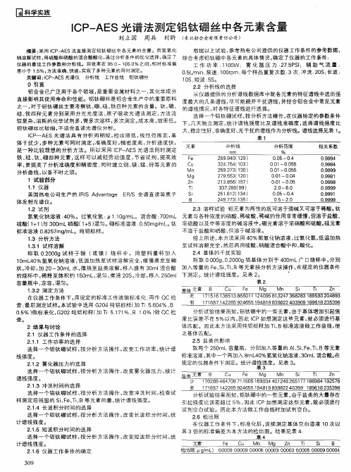
O 引 言 22 分析 线 的选 择 _ 铝 合金 已广 泛 用于 各 个 领 域 , 重 要 金属 材 料 之 一 , 是 其化 学 成 分 从仪器提供的分析谱线数据库 中就各元素的特征谱线中选出强 直 接 影 响其 使 用 寿命 和 性 能 。铝 钛 硼 丝 是 铝合 金生 产 中 的重 要 原 料 度 最 大 的 几 条谱 线 , 可 能避 开 干扰 谱 线 , 结合 铝 合 金 中常 见 元素 尽 并 之 一 , 于 铝 钛硼 丝 主 要 考察 钛 、 、 、 四 种 元素 的含 量。 钛 、 、 对 硼 硅 铁 硼 的谱 线 情 况 , 各特 征 谱 线进 行 选 择。 对 硅 、 四种 元 素 分 别 采 用 分 光 光 度 法 、 子 吸 收光 谱 法 测 定 , 法 流 铁 原 方 选 择一 个 铝 钛硼 试 样 , 分析 方法 操作 , 仪 器 给定 的 参数 条 件 按 在 较复杂, 消耗 的化 学 试 剂 多 , 多 次溶 样 , 次 测定 。 本 高 , 需 多 成 效率 低 。 下 , 天独 立 测 定 , 计 谱 线 强 度 比及 谱 线 准确 度 , 择 谱线 强 度 比 几 统 选
6066AlSiCp复合材料的制备工艺与性能的研究的开题报告

6066AlSiCp复合材料的制备工艺与性能的研究的开题报告一、研究背景和意义随着现代制造业的发展,高性能复合材料逐渐被广泛应用于航空航天、汽车、船舶等领域。
其中,6066AlSiCp复合材料由于其高强度、高刚度、高导热性、低热膨胀系数等优异性能,成为研究热点之一。
该复合材料由铝基合金矩形棒料和硅碳化物颗粒组成,其制备工艺和复合界面性能直接影响着材料的性能。
因此,对6066AlSiCp复合材料的制备工艺与性能进行研究具有重要的实际意义和应用前景。
二、研究内容和目标本课题拟对6066AlSiCp复合材料的制备工艺和性能进行研究,研究内容包括:1. 确定制备工艺参数,包括铸造温度、硅碳化物颗粒掺量等;2. 制备不同比例的6066AlSiCp复合材料试样;3. 测试试样的力学性能,包括抗拉强度、屈服强度、弹性模量等;4. 测试试样的导热性能,包括热导率、热膨胀系数等;5. 分析试样的组织结构和断口形貌。
本研究的目标是通过实验研究,掌握6066AlSiCp复合材料的制备工艺和性能,为制备高性能的铝基复合材料提供参考依据。
三、研究方法和计划本研究采用以下方法:1. 确定制备工艺参数:通过实验确定铸造温度和硅碳化物颗粒掺量的最佳参数;2. 制备试样:按照确定的工艺参数制备不同比例的6066AlSiCp复合材料试样;3. 测试力学性能:使用万能试验机测试试样的力学性能;4. 测试导热性能:使用热导仪测试试样的导热性能;5. 分析组织结构和断口形貌:使用扫描电镜对试样的组织结构和断口形貌进行分析。
本研究计划如下:第一年:确定制备工艺参数,制备6066AlSiCp复合材料试样;第二年:测试力学性能和导热性能,分析试样的组织结构和断口形貌;第三年:总结实验结果,撰写论文和发表文章。
四、预期成果及应用前景本研究将获得6066AlSiCp复合材料的制备工艺和性能数据,为制备高性能的铝基复合材料提供参考。
同时,研究结果可应用于航空航天、汽车、船舶等领域,推动我国高性能复合材料的发展。
ICP-AES光谱法测定铝钛硼丝中各元素含量5页

ICP-AES光谱法测定铝钛硼丝中各元素含量0 引言铝合金已广泛用于各个领域,是重要金属材料之一,其化学成分直接影响其使用寿命和性能。
铝钛硼丝是铝合金生产中的重要原料之一,对于铝钛硼丝主要考察钛、硼、硅、铁四种元素的含量。
钛、硼、硅、铁四种元素分别采用分光光度法、原子吸收光谱法测定,方法流较复杂,消耗的化学试剂多,需多次溶样,多次测定。
成本高,效率低。
铝钛硼丝比较细,不适合直读光谱仪分析。
ICP―AES光谱法具有分析周期短,检出限低,线性范围宽,基体干扰少,多种元素可同时测定,准确度好,精密度高,分析速度快,是一种比较理想的分析方法。
所以采用ICP-AES光谱法同时测定铁、硅、钛、硼四种元素,这样可以减轻劳动强度,节省试剂,提高效率,更提高了分析准确度和精密度;同时建立铜、镁、锰、锌等元素的分析曲线,以备不时之须。
1 试验部分1.1 仪器美国热电公司生产的IRIS Advantage ER/S 全谱直读等离子体发射光谱仪。
1.2 试剂氢氧化钠溶液:40%。
过氧化氢:ρ1.10g/mL。
混合酸:700mL硫酸(1+1)与300mL硝酸(1+5)混匀。
硼标准溶液:0.50mg/mL。
钛标准溶液0.8257mg/mL。
纯铝标样。
1.3 分析方法1.3.1 试样溶解称取0.2000g试样于银(或镍)烧杯中,用塑料量杯加入10mL40%氢氧化钠溶液,低温加热至试样溶解完全,缓慢蒸发至糊状,冷却,加20~30mL水,微热至盐类溶解,移入盛有30ml混合酸的烧杯中,稀释至体积约150mL,混匀,煮沸20S,冷却,移入250ml容量瓶中,定容,混匀。
1.3.2 测定方法在仪器工作条件下,用设定的标准工作液做标准化;再作QC检查;最后测定试样。
本试验中选用G204纯铝标样(加Ti 5.604%、B 0.5%)做标准化,G202纯铝标样(加Ti 5.171%、B 1.0%)做QC检查。
2 结果与讨论2.1 仪器工作条件的选择2.1.1 工作功率的选择选择一个铝钛硼试样,按分析方法操作,改变工作功率,统计谱线强度。
alsic电子封装材料热导率以及散热特性
AlSiC介绍 ALSIC微电子封装材料是西安明科微电子材料有限公司与西北工业大学合作开发的新一代电子产品。
明科公司(Xi'an Miqam Microelectronics Materials Co., Ltd)是目前国内唯一一家可以生产这种材料的企业。
铝碳化硅(AlSiC)金属基热管理复合材料,是电子元器件专用电子封装材料,主要是指将铝与高体积分数的碳化硅复合成为低密度、高导热率和低膨胀系数的电子封装材料,以解决电子电路的热失效问题。
AlSiC的性能特点■ AlSiC具有高导热率(170~200W/mK)和可调的热膨胀系数(6.5~9.5×10-6/K),因此一方面AlSiC的热膨胀系数与半导体芯片和陶瓷基片实现良好的匹配,能够防止疲劳失效的产生,甚至可以将功率芯片直接安装到AlSiC基板上;另一方面AlSiC的热导率是可伐合金的十倍,芯片产生的热量可以及时散发。
这样,整个元器件的可靠性和稳定性大大提高。
■ AlSiC是复合材料,其热膨胀系数等性能可通过改变其组成而加以调整,因此电子产品可按用户的具体要求而灵活地设计,能够真正地做到量体裁衣,这是传统的金属材料或陶瓷材料无法作到的。
■ AlSiC的密度与铝相当,比铜和Kovar轻得多,还不到Cu/W 的五分之一,特别适合于便携式器件、航空航天和其他对重量敏感领域的应用。
■ AlSiC的比刚度(刚度除以密度)是所有电子材料中最高的:是铝的3倍,是W-Cu和Kovar的5倍,是铜的25倍,另外AlSiC的抗震性比陶瓷好,因此是恶劣环境(震动较大,如航天、汽车等领域)下的首选材料。
■ AlSiC可以大批量加工,但加工的工艺取决于碳化硅的含量,可以用电火花、金刚石、激光等加工。
■ AlSiC 可以镀镍、金、锡等,表面也可以进行阳极氧化处理。
■ 金属化的陶瓷基片可以钎焊到镀好的AlSiC基板上,用粘结剂、树脂可以将印制电路板芯与AlSiC粘合。
ICP―AES法对耐磨高铬合金铸铁中锰、铬、铜、钼、镍的快速联合测定3页word
ICP―AES法对耐磨高铬合金铸铁中锰、铬、铜、钼、镍的快速联合测定耐磨高铬合金铸铁以其良好的耐磨、耐蚀及耐热性能在工业生产中得到了广泛的应用。
因该类样品样品含碳、铬较高,因此用常规硝-硫混酸或硝酸不易溶解,尤其是碳化铬、钼破坏不完全,严重影响分析结果。
单个元素分析又难以满足快速分析的要求。
本文在文献[1-5]的基础上,采用王水溶解耐磨高铬合金铸铁试样,硫-磷混酸高温下滴加硝酸氧化发烟以破坏碳化物,控制试验条件,对其中的锰、铬、铜、钼、镍采用电感耦合等离子体发射光谱法进行联合测定,由于这种方法既能使操作简化,节约药品和时间,又能保证分析的准确度,因而很值得在分析工作中推广。
1 试验部分1.1 仪器与试剂1.1.1 仪器Thermo 6300型电感耦合等离子体发射光谱仪。
1.1.2 试剂王水:硝酸与盐酸(1+3)混合;硫―磷混酸(1+1):硫酸、磷酸二者等体积混合;浓硝酸。
1.2 仪器工作条件高频输出功率1.15kw;雾化气流量0.5L?min-1;辅助气流量0.5 L?min-1;观测高度:12mm;积分时间30ms。
测定波长:在谱线库中选出各待测元素的分析谱线,通过比较相对强度、峰值、级次及干扰情况,选择比较灵敏的谱线作分析线[2]。
通过背景和干扰元素校正功能,试验了各测量元素的多条谱线,确定了适宜的分析谱线。
锰的测定波长:Mn257.610nm;铬的测定波长:Cr283.563nm;铜的测定波长:Cu324.754nm;钼的测定波长:Mo202.030nm;镍的测定波长:Ni221.647nm。
2 试验方法2.1 样品的处理称取试样0.2000g于250 ml钢铁量瓶中,加王水10ml,低温加热溶解后,加硫―磷混酸(1+1)15ml,加热至冒硫酸烟(在冒烟前分次滴加硝酸破坏碳化物,高碳、高铬及高铬钼试样,在冒硫酸烟时滴加硝酸破坏碳化物)至溶液清晰,碳化物全部破坏为止,取下冷却,加水30ml,煮沸取下冷却,定容作为试液。
玻纤增强材料表面浮纤表征手段
玻纤增强材料表面浮纤表征手段玻纤增强材料(Fiber Reinforced Composite Material)是一种由纤维增强材料和树脂基体构成的复合材料。
玻纤增强材料具有高强度、高硬度、轻质等优点,因此被广泛应用于各个领域。
不过,玻纤增强材料的表面浮纤问题一直是制约其应用的难点之一。
表面浮纤指的是玻纤增强材料表面的细小纤维裸露出来,这些浮纤可能会影响材料的力学性能和使用寿命。
针对这个问题,科学家们提出了一些表面浮纤表征手段,下面将介绍其中的几种方法。
1. 大气激光扫描显微镜(Atmospheric Laser Scanning Microscope,ALSM)ALSM是一种高分辨率的显微镜,可以对玻纤增强材料表面进行快速、大面积、无接触的扫描,得到高清晰度的浮纤图像。
该技术在浮纤表征中得到了广泛应用,尤其是在检查材料表面的微小缺陷方面应用更为广泛。
ALSM还可以配合图像处理软件进行定量分析,得到浮纤的数量、长度、密度等信息。
2. 感应耦合等离子体(Inductively Coupled Plasma,ICP)ICP是一种对玻纤增强材料表面进行粗糙度分析的手段。
该技术通过将玻纤增强材料置于带有阴极和阳极的溶液中,施加电压使阳极表面产生等离子体,然后检测这些等离子体与玻纤增强材料表面产生的反应。
这种反应可以得出玻纤增强材料表面的纤维尺寸和数量。
3. 扫描电子显微镜(Scanning Electron Microscope,SEM)SEM是一种能提供高分辨率表面形貌信息的显微镜。
它可以通过聚焦电子束对材料表面进行扫描,得到高清晰度的电子图像。
在玻纤增强材料的浮纤表征中,SEM可以得到浮纤的形态、尺寸和分布情况。
相比其他表面浮纤表征手段,SEM具有更高的分辨率和更准确的浮纤信息。
除了以上三种常用的手段之外,还有许多其他技术用于玻纤增强材料表面浮纤的表征和分析,如激光剥离法、粒子图像测速、红外光谱学等。
ICP-AES光谱法测定55%铝锌合金中的硅
ICP-AES光谱法测定55%铝锌合金中的硅吴益青陈信钢何志明(梅山钢铁公司制造管理部南京210039)摘要:使用氢氧化钠溶液和盐酸先后分解55%铝锌硅合金,ICP-AES光谱法(电感耦合等离子体发射光谱法)测定溶解完全55%铝锌硅合金溶液中硅的含量,探索了各影响因素对实验结果的影响,如分析线、RF功率、铝锌基体、氯化钠基体等干扰。
确定最佳实验条件,方法检出限为0.009%,精密度RSD小于1.2%,回收率为98%~100.44%。
关键词:55%铝锌硅合金;硅;电感耦合等离子体发射光谱法Determination of Silicon Content in55%Aluminium Zinc Silicon Alloy by ICP-AESWU Yiqing CHEN Xingang HE Zhiming(Manufactu/ng Management Depa/ment of Meishan Iron&Steel Co.,Nanjing210039,China) Key words:55%aluminium zinc silicon alloy;silicon%inductively coupled plasma atomic emission spectrometry(ICP一AES)硅元素的检测方法有硅钼蓝光度法[1]、重量法⑵,无论是硅钼蓝光度法还是重量法都有耗时长的缺点,而且仅只能测硅这唯一元素,效率低。
当下电感耦合等离子体光谱法效率高,将影响检测的干扰因素去除,不仅可以准确测定痕量元素,而且可以同时测定多种元素[3-4]&针对55%铝锌合金的特殊性,铝量高难溶于酸,使用氢氧化钠溶液和盐酸先后分解55%铝锌硅合金,试样分解后,再用电感耦合等离子体光谱法测定硅含量,该方法操作简便、效率高,准确度有保证,方法检出限为0.009%,RSD小于1.2%,回收率$98%~100.44%。
铸件表面质量要求

ASTM A802 Standard Practice for Steel Castings, Surface Acceptance Standards, Visual Examination
GEWE.all._spc_castings_supplement.GEEN.00 (392A1165)
Non Critical Areas
Gas Porosity Quality Level C2
No acceptable
Gas Porosity Quality Level C3
Critical Areas & Non Critical Areas
Non Metallic Inclusions Quality Level B1
Non Acceptable
Non Metallic Inclusions Quality Level B2
Non Aceptable
Non Metallic Inclusions Quality Level 4
Non Aceptable
Solidification Discontinuity Level D1
(4 levels) H – Metal Removal Marks – Surface remaining after using a mechanical means of dressing a cast surface or
a previously thermally dressed surface (4 levels) J – Metal Removal Marks – Welds. Indications of welds fully or partially removed by thermal or mechanical dressing
- 1、下载文档前请自行甄别文档内容的完整性,平台不提供额外的编辑、内容补充、找答案等附加服务。
- 2、"仅部分预览"的文档,不可在线预览部分如存在完整性等问题,可反馈申请退款(可完整预览的文档不适用该条件!)。
- 3、如文档侵犯您的权益,请联系客服反馈,我们会尽快为您处理(人工客服工作时间:9:00-18:30)。
Applied Mechanics and Materials Vol. 42 (2011) pp 363-366 Online available since 2010/Nov/11 at © (2011) Trans Tech Publications, Switzerland doi:10.4028//AMM.42.363Study on Surface Quality of Al/SiCp Composites with Ultrasonic Vibration High Speed Milling Daohui Xianga, Xintao Zhi, Guangxi Yue, Guofu Gao and Bo ZhaoSchool of Mechanical and Power Engineering, Henan Polytechnic University, Jiaozuo 454000, China dhxiang@ Key words: Ultrasonic Milling, Al/SiCp composites, Surface Quality, Surface Microstructure, MMCsAbstract. Al/SiCp composites with excellent physical and mechanical properties are applied widely in the aerospace, automotive, national defense, electronics and other fields. High content and high hardness SiC particles lead to poor machinability and that further application is restricted. Surface microstructure and surface formation mechanism of Al/SiCp composites were studied under condition of ultrasonic vibration milling and conventional milling. The experimental results show that machined surface had the same defects, but SiC particles were mainly direct sheared in ultrasonic milling different from the conventional milling, the roughness (Ra) of the surface generated in the ultrasonic vibration milling was smaller. At last, the formation mechanism of surface topography in the ultrasonic milling was analyzed. The research indicated that ultrasonic milling could obtain better surface quality than conventional milling and with high efficient. Introduction Al/SiCp composites are widely applied in the aerospace, national defense and other fields, and are being researched and developed at above domain [1-3]. Due to SiC particles existence, Al/SiCp composites chip formation is similar to the crack propagation and fracture process of brittle materials, machined surface existing cracks and flaws [4, 5]. As the ultrasonic vibration cutting can reduce cutting force and cutting temperature, which has been researched in drilling and turning [6], it will be a useful trial to apply ultrasonic vibration to the machining of Al/SiCp composites. According to correlative literature, no research has yet been carried out on Al/SiCp composites with ultrasonic milling; in addition, SiC particles content of volume was lower than 40% in the previous researches. When SiC particles content of volume is higher than 40%, tool wear is very serious, so that it is difficult to cut with the current conventional methods. At present, with the development of material, the higher SiC content of volume in MMCs materials is needed especially in aerospace fields. Milling is the only method of achieving efficient machining of cast Al/SiCp composites with variation shapes and larger machining allowance, particularly in many cavity machining. So roughness and surface quality of high volume Al/SiCp composites in ultrasonic milling were researched and analyzed in this paper. Experimental Equipment and Methods PCD milling cutter has been widely applied on high efficiency, precision machining of the non-ferrous materials [7]. Hence, PCD cylindrical end milling cutter with diameter 6 mm and 3 blades is used. The type of machining center is DMU80U with the spindle speed of 20~20000 r/min. The size and content of SiC particles contained in the Al/SiCp composites are 30μm and 65% respectively. Hardness of SiC particles is HV 11.9~12.6 GPa. Ultrasonic vibration produced by self-made vertical vibration device is acted on the tool and its direction is longitudinal in ultrasonic vibration milling. And amplitude and frequency of ultrasonic vibration are 15μm and 35kHz respectively(as shown in Fig.1). Machined surface is observed with the scanning electron microscopy S-520-type SEM. Roughness of machined surface is measured with JJI-B-type three-parameter surface roughness measuring instrument. The experiment is carried out betweenAll rights reserved. No part of contents of this paper may be reproduced or transmitted in any form or by any means without the written permission of TTP, . (ID: 112.122.130.188-29/03/12,13:52:36)364History of Mechanical Technology and Mechanical Designconventional milling and ultrasonic milling at the same situation where only milling speed changes from 113 m/min to 337 m/min, and invariable feed engagement, milling depth, milling width is 0.02mm/z, 0.2mm, 6mm respectively.1.8 1.6 1.4ultrasonic milling conventional millingRoughness Ra [µm]1.2 1.0 0.8 0.6 0.4 0.2 0.0 100 150 200 250 300 350Milling speed [m/mm]Fig. 1The schematic for ultrasonic milling apparatusFig. 2The effect of the milling speed on surface roughnessExperimental Results and Analysis Surface Roughness in Ultrasonic Vibration Milling and Conventional Milling. Milling speed is changed from 113 m/min to 337 m/min, but feed and depth of milling are respectively remained 0.02 mm/z and 0.2 mm during conventional milling and ultrasonic milling. Surface roughness (Ra) of Al/SiCp composites is shown in Fig. 2. As can be seen from Fig.2, surface roughness gradually increases as the milling speed (lower than 290m/min) increase in both ultrasonic vibration and conventional milling. As the cutting speed increases, cracks can easily cross high strength SiC particles and expand, thus results in more fragmentation of SiC particles in the non-directional slip of matrix. But, surface roughness value under the condition of ultrasonic vibration milling is smaller than those of conventional milling. This is because that the homogeneous vibration tool indirectly contacts with the workpiece, and the workpiece cooling conditions in the cutting area could achieve improvement. Thus the material surface is uniformly removed, with surface carved out of uniform depth. So the surface roughness is small in ultrasonic vibration milling. Effect of SiC Particles on the Machined Surface in the Ultrasonic Milling. Analysis on surface microstructure is carried out in the ultrasonic milling. All the images are obtained by the SEM at the condition where milling speed, feed, depth and width of milling are respectively remained 262 m/min, 0.2 mm/z, 0.6 mm and 6mm. Fig. 3 shows the damaged surface caused by SiC particles in the ultrasonic milling with PCD milling cutter. Fig. 3(a) shows the images of the direct sheared SiC particles. This phenomenon is expected in the machining of Al/SiCp composites. Sharp cutting nose accumulating a great deal of energy in the ultrasonic vibration conditions could directly shear silicon carbide particles, easily. Fig. 3(b) shows the SEM images of surface microstructure pressed into by SiC particles. When the cutting edge encounters the upper of SiC particles in the later period, SiC particles were pressed into the soft matrix by flank. Fig. 3(c) shows that SiC particles are pulled-out of matrix. Shear stress is greater than bonding strength between the SiC particles and the matrix, when the cutting edge encounters the bottom of SiC particles, SiC particles are pulled out from the soft matrix. Fig. 3(d) shows the defected surface of matrix scratched by SiC particles. The reasons are as follows. The size or shape of SiC particles is not the same and their distribution is discontinuous. Along with the tool wear in the later period of ultrasonic milling, fractured SiC particles could not effectively be cut, then accumulate on the rack face, then scratch the machined surface.Applied Mechanics and Materials Vol. 42365(a) SEM of sheared SiC particles(b) SEM of SiC particles pressed into the matrix(c) SEM of SiC particles pulled out (d) SEM of SiC particles scratch the surface Fig. 3 SEM of machined surface of Al/SiCp composites under the conditions of ultrasonic millingAnalysis of Surface Micro-morphology in Ultrasonic Vibration Milling. Machined surface micro morphology of the Al/SiCp composites under condition of ultrasonic vibration milling and conventional milling are showed in Fig. 4. From Fig. 4(a), we can see that majority SiC particles are directly sheared by the tool, few are pulled out of matrix, voids in surface are little, cracks and scratches in surface are not obvious at the junction of SiC particles and matrix. Fig. 4(b) shows there are many of voids and crack. From above, good surface quality was obtained by using ultrasonic vibration milling. The reason is that high hardness and high strength SiC particles are directly sheared by the PCD tool, not putted off the soft matrix under condition of ultrasonic vibration milling.(a) ultrasonic milling (b) conventional milling Fig. 4 Al/SiCp composites micro-morphology in milling Analysis of Experimental Results. Under the conventional milling conditions, existence of high hardness SiC particles results that the harmful vibration aggravate, tool sharpness gets down, tool flank wear increases, and cutting force and cutting heat of continuous milling increase. Hence, surface quality is poor in conventional milling. For the additional ultrasonic vibration existence, under the same conditions, ultrasonic milling can obtain better surface quality than conventional milling. The reasons are as follows. First, the contact of tool and chip is a discontinuous separation process, which has advantage of the cooling between chip and tool. Second, PCD tool nose gathered a great deal of energy in ultrasonic vibration, which can easily shear high hardness SiC particles directly. Third, milling cutter attached axial vibration has advantage of reducing torque in the milling and enhancing the rigidity of milling366History of Mechanical Technology and Mechanical Designcutter, can achieve a smooth cutting of Al/SiCp composites, and effectively avoid that the pulled-out SiC particles scratch the machined surface and other defects. In addition, additional axial vibration is equal to the rolling on the surface by the tool flank, which can greatly increase surface smoothness. Conclusions Through the study of Al/SiCp composites micro-morphology in ultrasonic vibration milling and conventional milling, SiC particles affect on the surface in ultrasonic vibration milling is identical to conventional milling. There are four types of SiC particles directly sheared, SiC particles pulled-out, SiC particles pressed into the matrix and matrix scratched. However, most SiC particles are directly sheared in ultrasonic vibration milling. From experiment it is found that when the cutting speed is below 290 m/min, the surface roughness values in the ultrasonic vibration milling are smaller than conventional milling. Therefore, ultrasonic vibration milling can get a better surface quality in practical work and improve machining efficiency. Milling cutter attached axial vibration has advantage of reducing torque in the milling and enhancing the rigidity of milling cutter, can get better surface quality. Hence, axial ultrasonic vibration technology can expand the range of machining components in the practical production, with the capable of machining large, thin-walled parts. Acknowledgement This topic of research is supported by National Natural Science Foundation of China (No. 50975080), Foundation of He’nan Educational Committee (No. 2010A460008), Research Fund for the Doctoral Program of Henan Polytechnic University (No. B2009-71) and Key Laboratory of Mechanical Engineering of Henan Province. Reference [1] Cole GS and Sherman AM: Materials Characterization, Vol. 35 (1995), pp.3-9. [2] Davim JP and Baptista AM: Journal of Materials Processing Technology, Vol. 103 (2000), pp. 417-423. [3] Lin JT, Bhattacharyya D and Ferguson GW: Composites Science and Technology, Vol. 58 (1998), pp.285-291. [4] A.B. Sadat and M.Y. Reddy: Experimental Mechanics, Vol. 33 (1993), pp. 343–348. [5] A. Abdel Hamid, A.S. Wifi and M. El-Gallab: Journal of Materials Processing Technology, Vol. 56 (1996), pp. 643-654. [6] Z.X.Tie and B.Zhao: Manufacturing Technology & Machine Tool, Vol. 4 (2003), pp. 36-38 (In Chinese) [7] El-Gallab.M and Sklad. M: Journal of Materials Processing Technology, Vol. 83 (1998), pp. 151-158History of Mechanical Technology and Mechanical Design 10.4028//AMM.42Study on Surface Quality of Al/SiCp Composites with Ultrasonic Vibration High Speed Milling 10.4028//AMM.42.363 DOI References [1] Cole GS and Sherman AM: Materials Characterization, Vol. 35 (1995), pp.3-9. doi:10.1016/1044-5803(95)00063-1 [4] A.B. Sadat and M.Y. Reddy: Experimental Mechanics, Vol. 33 (1993), pp. 343–348. doi:10.1007/BF02322151。