SIHFBC30S中文资料
CC4H-4S中文资料

Multiport Analog Modem CardBenefits• High-density , V .92 connections • V .34/33.6K Super G3 fax with Error Correction Mode • Supports leading remote access and fax software • Universal PCI and PCI ExpressThe MultiModem ® ISI server card is ideal for small- to mid-sized companies requiring analog dial-up remote access or a dedicated fax server solution. It provides up to eight built-in V .92/56K modems for cost-effective,high-density , server-based remote access. The MultiModem ISI server card also offers V .34/33.6K Super G3 fax and Error Correction Mode, that can reduce fax transmission time by more than half when compared to traditional fax modems.Features• Four or eight integrated V .92/56K modems• V .92/56K download speeds and 48K upload speeds when connecting with V .92 servers • Class 1.0 and Class 2.1 faxing at speeds to V .34/33.6K bps (Super G3)• Error Correction Mode (ECM) provides fast and reliable fax transmissions • V .44 compression improves data throughput rates • U.S. Caller ID reporting• Sustained data rates to 460.8K per port • Phone cables included• Compatible with Windows ® 2000/XP/2003/Vista/2008 (32-bit/64-bit) and Linux • Up to 4 cards per server• Remote configuration for centralized setup and mangement • 3.3V and 5V Universal PCI or PCI Express models • Compatible with PCI-X slot (Universal PCI models)• Flash memory for easy updates • T wo-year warrantyMultiModem ®ISIWorld Headquarters Tel: (763) 785-3500 (800) EMEA Headquarters Multi-Tech Systems (EMEA)United KingdomTel: +(44) 118-959 7774Multi-Tech Systems (EMEA) FranceTel: +(33) 1 49 19 22 06HighlightsCost-Effective & Scalable. The MultiModem ISI server card provides four or eight dial-up sessions using only one server slot. When demand exceeds one modem card, you can simply add up to three additional cards.V.92 Dial-out Connections. The MultiModem ISI server card supports V .92/56K dial-out and V .34/33.6K dial-inconnections. With V .92 dial-out, you can achieve an upload speed of 48K bps (30% increase over V .90 modems).Enhanced Fax Features. The MultiModem ISI server card supports V .34 fax and Error Correction Mode providingsignificant performance and reliability enhancements over previous fax standards. V .34 sends and receives faxes at speeds up to 33.6K, more than double the speed of the V .17/14.4K fax standard. Error Correction Mode adds reliablility while increasing performance of faxtransmissions. Together these enhancements increase the performance of the MultiModem ISI server card to levels previously only found in more expensive dedicated fax boards and machines.V.44 Compression. V .44 compression standard improves V .42bis data compression anywhere from 20 to 60%, up to as much as 200% for certain types of highly compressible data. This compression technique enables data throughput rates of higher than 300K bps.Simplify Remote Access. The fully-integrated MultiModem ISI server card is easy to set up and manage. You only have to connect the phone lines. There are no external modems and power cords to hassle with; plus it saves back office space since the modems are on the prehensive Service and Support. The Multi-Techcommitment to service means we provide a two-year product warranty and service that includes free telephone technical support, 24-hour web site and ftp support.Ordering InformationProductDescriptionRegion ISI5634UPCI/8 V .92, 8-Modem Card - Universal PCI Global ISI5634UPCI/4 V .92, 4-Modem Card - Universal PCI Global ISI9234PCIE/8 V .92, 8-Modem Card - PCI Express Global ISI9234PCIE/4V .92, 4-Modem Card - PCI ExpressGlobalSpecificationsModemData: V .92, V .90, enhanced V .34, V .32bis, V .22bis Error Correction: V .42, MNP Class 3 & 4Data Compression: V .44, V .42bis, MNP Class 5FaxStandards: V .34, V .17, V .29, V .27ter, V .21, T.30, T.30Annex A, T.30 Annex F , T.31, T.31 Annex B, T.32 Annex C, TR29.2 Class 2 RecommendationRates: 33.6K, 31.2K, 28.8K, 26.4K, 24K, 21.6K, 19.2K, 16.8K, 14.4K, 12K, 9600, 7200, 4800, 2400, 300 bps Error Correction: ECMCompression: MH (T.4), MR (T.4), & MMR (T.6)Conversion: Real time (on-the-fly) compression conversionCommands: Class 1, 2, 1.0, 2.0, 2.1Bus Type3.3V & 5V Universal PCI or PCI Express (x1)Operating System SupportWindows 2000/XP/2003/Vista/2008 (32-bit/64-bit) & LinuxCablingFan out cable with 1 or 2 RJ45 connectors & 4 or 8 RJ11 connectorsPhysical DescriptionUniversal PCI Models:13.87" L × 4.97" W; 8.7 oz (35.2 cm × 12.6 cm; 247 g)PCI Express Models:13.87" L × 4.97" W; 8.5 oz (35.2 cm × 12.6 cm; 241 g)Operating EnvironmentTemperature Range: +23° to +140° F (-5° to +60° C)ApprovalsCE MarkEMC: FCC Part 15 Class B, EN 55022, EN 55024Safety: UL/cUL 60950-1, EN 60950-1, AS/NZS 60950:2000, CCCTelecom: 47CFR Part 68, CS03, TBR21Other countries also includedCopyright © 2008 by Multi-Tech Systems, Inc. All rights reserved.6/08 86000323Made in Mounds View, MN, U.S.A.Features and specifications are subject to change without notice.Trademarks / Registered Trademarks: MultiModem, Multi-Tech, and theMulti-Tech logo: Multi-Tech Systems, Inc. / All other products and technologies are the trademarks or registered trademarks of their respective holders.。
SMP4ECS79S 迪士热水器用户手册说明书
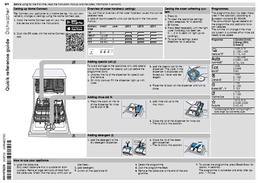
cordingly.
4. To save the settings, press
for 3 seconds.
Adding special salt
To avoid damage to the appliance, only add special salt to the dispenser for special salt just before the programme starts. 1. Unscrew the lid of the dispenser for special salt
and remove. 2. On initial start-up: Fill the dispenser right up with
water.
3. Add the special salt to the dispenser. The water in the dispenser is displaced and forced out. Never add detergent.
Cause and troubleshooting
Supply hose is kinked. ▶ Install the supply hose without kinks.
Water tap is turned off. ▶ Turn on the water tap.
Water tap is jammed or furred up. ▶ Turn on the water tap.
Tip: Connect your appliance to a mobile device. You can conveniently change all settings using the Home Connect app. 1. Install the Home Connect app on your mo-
FOSS官方资料 FT120中文操作手册
MilkoScan FT-120乳品分析仪中文操作手册北京福斯杰科技有限公司F os s C hi na Se r vi c e Ce n te r2000年6月目录第1章简介 (5)§1。
1FT—120乳品分析仪 (5)§1。
2关于这本手册 (6)§1。
3福斯电子的校准模块 (6)§1。
4FT—120仪器可选择的模块 (7)§1。
4。
1自动清洗和调零模块(ACZ) (7)§1。
4。
2 应用模块 (7)§1。
4。
3 天平选项 (7)§1。
4。
4 高级性能模块 (7)§1。
4。
5高级校准模块 (8)§1。
4。
6 输入选择模块 (8)§1。
4。
7 数据交换选择模块(DDE) (8)§1。
4。
8 品质确认模块 (8)§1。
5窗口系统 (9)§1。
5。
1 菜单栏 (9)§1。
5。
2 功能键 (10)§1。
5。
3 按钮栏 (10)§1。
5。
4 滚动栏 (10)§1。
5。
5 状态栏 (10)§1。
6定义自己的窗口 (10)§1。
7仪器语言支持 (10)§1。
7。
1 怎样使用当地语言 (11)§1。
8激光的保险装置 (11)第2章FT—120乳品分析仪用户界面 (11)§2。
1FT—120乳品分析仪插图屏幕说明 (12)§2。
2按钮板 (13)§2。
3功能键 (13)§2。
4快捷键 (14)§2。
5其它菜单 (14)§2。
6菜单概要 (15)§2。
6。
1 菜单中的基本模块 (15)§2。
6。
2 应用模块菜单 (16)§2。
7物理连接与转换 (16)第3章操作 (18)§3。
1调零和实验样品 (18)§3。
优化器的技术说明书:S系列
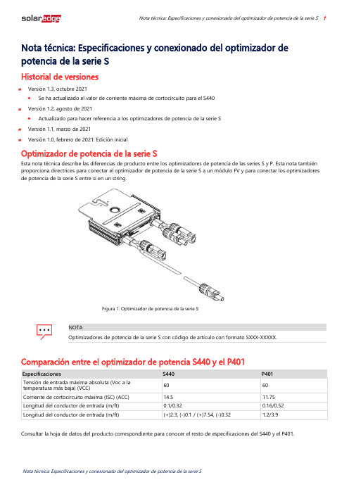
Nota técnica: Especificaciones y conexionado del optimizador de potencia de la serie S 1Nota técnica: Especificaciones y conexionado del optimizador de potencia de la serie SHistorial de versionesVersión 1.3, octubre 2021•Se ha actualizado el valor de corriente máxima de cortocircuito para el S440Versión 1.2, agosto de 2021•Actualizado para hacer referencia a los optimizadores de potencia de la serie SVersión 1.1, marzo de 2021Versión 1.0, febrero de 2021: Edición inicialOptimizador de potencia de la serie SEsta nota técnica describe las diferencias de producto entre los optimizadores de potencia de las series S y P. Esta nota también proporciona directrices para conectar el optimizador de potencia de la serie S a un módulo FV y para conectar los optimizadores de potencia de la serie S entre sí en un string.Figura 1: Optimizador de potencia de la serie SNOTAOptimizadores de potencia de la serie S con código de artículo con formato SXXX-XXXXX. Comparación entre el optimizador de potencia S440 y el P401Especificaciones S440 P401Tensión de entrada máxima absoluta (Voc a latemperatura más baja) (VCC) 60 60 Corriente de cortocircuito máxima (ISC) (ACC) 14.5 11.75 Longitud del conductor de entrada (m/ft) 0.1/0.32 0.16/0.52 Longitud del conductor de entrada (m/ft) (+)2.3, (-)0.1 / (+)7.54, (-)0.32 1.2/3.9Consultar la hoja de datos del producto correspondiente para conocer el resto de especificaciones del S440 y el P401.Nota técnica: Especificaciones y conexionado del optimizador de potencia de la serie SS 2 Comparación de los conductores del conector de los optimizadores de potencia de las series S y P Una de las mejoras del optimizador de potencia de la serie S con respecto al de la serie P es la diferencia de longitud entre los conductores del conector de salida positivo y negativo. El conductor del conector de salida positivo del optimizador de potencia de la serie S es largo, mientras que el de salida negativo es corto. La disposición sitúa la conexión entre los dos conductores cerca del optimizador de potencia. Esto evita que el conector cuelgue del tejado y quede expuesto cuando hay humedad.Conductores del conector del optimizador de potencia de la serie S Conductores del conector del optimizador de potenciade la serie PFigura 2: Comparación de las dimensiones y los conductores de entrada y salida de los optimizadores de potencia de las series S y PNota técnica: Especificaciones y conexionado del optimizador de potencia de la serie S 3 Conexión del optimizador de potencia de la serie S a un módulo FVConectar los optimizadores de potencia de la serie S a un módulo FV conectando los conectores de salida del módulo FV a los conectores de entrada del optimizador de potencia como se indica en los pasos de esta sección y en la figura 2, Dibujo esquemático de los conductores de entrada y salida de la serie S y sus dimensiones.Conexión de un optimizador de potencia de la serie S a un módulo FV1.Conectar el conector de salida positivo (+) del módulo al conector de entrada positivo (+) del optimizador de potencia.2.Conectar el conector de salida negativo (-) del módulo al conector de entrada negativo (-) del optimizador de potencia.3.Repetir los pasos de conexión en cada optimizador de potencia de la serie S.Conexión de los optimizadores de potencia de la serie S en stringsEsta sección le guía por el proceso de conexión de los optimizadores de potencia de la serie S en strings.Conexión de los optimizadores de potencia de la serie S entre sí en strings1.Extender el conector de salida positivo (+) del primer optimizador de potencia hacia el conector de salida negativo (-) del segundo optimizador de potencia e insertar el conector de salida positivo (+) en el conector de salida negativo (-) para realizar la conexión.2.Conectar el resto de los optimizadores de potencia del string de la misma forma. Consultar el manual de instalación del inversor SolarEdge para conocer todas las pautas de instalación.NOTAEn la figura 3 se ilustra el patrón de conexión del cableado de entrada entre los optimizadores de potencia de laserie S y un módulo FV, y las conexiones del cableado de salida entre los optimizadores de potencia de unstring. Consultar la etiqueta del producto para identificar los conectores de entrada y salida positivo y negativo.NOTAEl optimizador de potencia de la serie S puede instalarse con módulos de cajas de conexiones simples ydivididas.。
斯芬斯(Siemens)产品说明书:6GK5106-1BB00-2AA3 SCALANCE X106

Yes
(ABS)
● Bureau Veritas (BV)
Yes
● Det Norsቤተ መጻሕፍቲ ባይዱe Veritas (DNV)
No
● Germanische Lloyd (GL)
No
● DNV GL
Yes
● Lloyds Register of Shipping (LRS)
Yes
● Nippon Kaiji Kyokai (NK)
Siemens provides products and solutions with industrial security functions that support the secure operation of plants, solutions, machines, equipment and/or networks. They are important components in a holistic industrial security concept. With this in mind, Siemens’ products and solutions undergo continuous development. Siemens recommends strongly that you regularly check for product updates. For the secure operation of Siemens products and solutions, it is necessary to take suitable preventive action(e.g. cell protection concept) and integrate each component into a holistic, state-of-the-art industrial security concept. Thirdparty products that may be in use should also be considered. For more information about industrial security, visit /industrialsecurity. To stay informed about product updates as they occur, sign up for a product-specific newsletter. For more information, visit . (V3.4)
C-Flex 072 熟性塑料合成吸引器管说明书

Typical physical properties of C-Flex®Property ASTM MethodFormulations Value or Rating 374 082072Appearance–TranslucentTranslucentOpaque Durometer, Shore A D2240606060T ensile Strength, psi D412119011061196Elongation, %D412915874862T ensile Modulus, @100%/300%, psi D412244/385256/400247/389T ensile Set @ 300% StretchD412242926Compression Set Constant Defl., "B" (22hrs @ 70°C), %D395838986Brittle Point, °CD746-66-67-68Chemical resistance Acids, Dilute/WeakAcceptable Acids, Strong/Concentrated Acceptable Bases, Dilute/WeakAcceptable Bases, Strong/Concentrated Acceptable SaltsAcceptable High-purity Water Acceptable AlcoholNot recommended*Oil/Water Emulsion T est before using Organic SolventNot recommendedComparative opaque TPE peristaltic pump tubing lifeThe table below shows average hours until rupture of 1/4" ID x 3/8" OD (6.4 mm x 9.5 mm) tubing having undergone gamma irradiation. Samples were pumped using a 3-roller pump head operating at 300 rpm with 10 psi back pressure, at room temperature.The performance of tubing in peristaltic pumping applications is affected by the conditions of use and equipmen utilized, along with size and all thickness of the tubing tested. The data above is presented forinformation only and should not be utilized for specification purposes.Unless otherwise noted, all tests were conducted at room temperature (73°F). Values shown were determined on 0.075" thick molded ASTM plaques.*Brief or intermittent contact is acceptable.NOTE: It is the users responsibility to insure the suitability and safety of C-Flex® for all intended uses/applications.One-piece overmolded C-Flex® manifold maintains innerbore diameters with superior reliability and product integrity.C-Flex® comes in a wide variety of sizes and formulations.NOTE: C-Flex® tubing will deteriorate with repeated autoclaving. Radiation is the recommended method of sterilization for all C-Flex® thermoplastic materials.CharacteristicsThe manufacturing process is carefully controlled from raw material compounding through finished production. Inspection and lot traceability information is readily accessible as batch numbers are assigned. All packages are identified by external labeling on both the bag and the crush-proof box.Saint-Gobain Performance Plastics' manufacturing facilities have the ability to create a variety of sizes or coil lengths for your particular application needs. Contact us for a quote to meet your specific requirements.FLS-5067O-0320-BPS©2020 Saint-Gobain Life SciencesSterilization MethodsAutoclavable one time 30 minute cycle at 121°C Gamma Irradiationone time up to 40kGyFLS-5067O-0320-BPS ©2020 Saint-Gobain Life SciencesContact us today for:Consultations • Samples • Quotes • Orders • Technical Service C-Flex® tubing standard size(1) FORMULAS: (xxx)072 - Opaque 082 - Translucent 374 - TranslucentFor registered access to Saint-Gobain Product Validation Summaries,CLICK HEREWorking pressures are calculated at a 3:1 ratio relative to burst pressure using ASTM D1599 and ISO 7751The values values listed for working and burst pressures are derived from tests conducted in laboratory conditions on unsterilized tubing. Many factors will reduce the tubing's ability to withstand pressure, including sterilization method, temperature, chemical compatibility, stress, pulsation and the attachment to fi ttings. It is imperative that the user conduct tests simulating the conditions of the application prior to specifying the tubing for use.IMPORTANT: It is the user’s responsibility to ensure the suitability and safety of Saint-Gobain Life Sciences products for all intended uses and that the materials to be used comply with all applicable medical regulatory requirements. Saint-Gobain Life Sciences assumes no responsibility for any product failures that occur due to misuse of the materials it provides arising out of the design, fabrication or application of the products into which the materials are incorporated.WARRANTY: For a period of 12 months from the date of first sale, Saint-Gobain Life Sciences warrants this product to be free of defects in materials and workmanship. Our only obligation will be to replace any portion proving defective, or at our option, to refund the purchase price there of.SAINT-GOBAIN LIFE SCIENCES DISCLAIMS ALL IMPLIED WARRANTIES OF MERCHANTABILITY AND FITNESS FOR A PARTICULAR PURPOSE.Uncontrolled Document - for the controlled version of this document please visit Saint-Gobain Life Sciences 4451 110th Avenue North Clearwater, FL 33762Tel: (727) 531-4191Fax: (727 530-5603Saint-Gobain Life Sciences La Mothe-aux-Aulnais F-89120 Charny, France Tel: (33) 3-86-63-78-78Fax: (33) 。
斯百瑞呼吸机介绍复习课程

斯百瑞呼吸机介绍斯百瑞呼吸机斯百瑞呼吸机,是湖南明康中锦医疗有限公司研发生产的呼吸机品牌。
其生产过程严格遵循ISO13485医疗器械质量管理体系要求实行科学,严谨生产。
并于2013年通过工信部双软认证。
企业愿景为打造国内自主研发生产的无创呼吸机品牌,建立完善的医疗云平台。
为患者提供科学,有效的无创通气治疗解决方案。
产品功能斯百瑞呼吸机主要分为医用和家用呼吸机两大类。
医用呼吸机:适用于慢性阻塞性肺疾病,阻塞性睡眠呼吸暂停综合征,呼吸功能不全,心功能不全,脊柱侧弯,术前准备和术后恢复,急性呼吸窘迫综合症,哮喘,间质性肺病等患者的通气护理。
家用呼吸机:适用于OSA患者和其他需要呼吸支持的治疗情况。
为治疗呼吸暂停而设计,它同时能够监测到呼吸暂停、低通气、打鼾、气流受限等事件,并能够对不同的呼吸事件自动作出反应及压力调整。
产品型号医用呼吸机产品:斯百瑞ST-30C 自动双水平无创呼吸机;斯百瑞ST-30A 自动双水平无创呼吸机;家用呼吸机产品:斯百瑞ST-30F 自动双水平无创呼吸机;斯百瑞CPAP-25 自动单水平无创呼吸机:斯百瑞CPAP -A25 自动单水平无创呼吸机;斯百瑞BPAP-30 自动双水平无创呼吸机;斯百瑞BPAP-A30 自动双水平无创呼吸机;产品优势1、3.5英寸彩屏大屏幕高清显示屏设计数据显示更全面,方便患者和家属全面掌握呼吸状况,更方便老年人以及监测夜间治疗数据使用,方便实用。
2、360防倒灌专利设计湿化器湿化器采用防倒灌技术,多档温度可调,满足患者的不同需求,提高护理的安全舒适度。
湿化器设计独具匠心,多档可调节温度设计能有效预防水分冷凝于管道及面罩中,提高产品依从性;360度防倒灌专利设计,能降低机器意外损坏的风险。
3、血氧监测功能同步显示血氧监测数据自动生成报告,实时监测11项专业治疗数据,随时了解治疗效果。
独具特色的客户服务平台,依靠呼吸机内置WIFI同步传输治疗数据,通过服务平台实时监测治疗状态,获取专业治疗报告。
FAIRCHILD FFH30S60S Stealth 2 Rectifier 数据手册

LIFE SUPPORT POLICY FAIRCHILD’S PRODUCTS ARE NOT AUTHORIZED FOR USE AS CRITICAL COMPONENTS IN LIFE SUPPORT DEVICES OR SYSTEMS WITHOUT THE EXPRESS WRITTEN APPROVAL OF FAIRCHILD SEMICONDUCTOR CORPORATION. As used herein: 1. Life support devices or systems are devices or systems which, (a) are intended for surgical implant into the body or (b) support or sustain life, and (c) whose failure to perform when properly used in accordance with instructions for use provided in the labeling, can be reasonably expected to result in a significant injury to the user. 2. A critical component in any component of a life support, device, or system whose failure to perform can be reasonably expected to cause the failure of the life support device or system, or to affect its safety or effectiveness.
- 1、下载文档前请自行甄别文档内容的完整性,平台不提供额外的编辑、内容补充、找答案等附加服务。
- 2、"仅部分预览"的文档,不可在线预览部分如存在完整性等问题,可反馈申请退款(可完整预览的文档不适用该条件!)。
- 3、如文档侵犯您的权益,请联系客服反馈,我们会尽快为您处理(人工客服工作时间:9:00-18:30)。
Power MOSFETIRFBC30S, SiHFBC30S, IRFBC30L, SiHFBC30LVishay SiliconixFEATURES•Surface Mount (IRFBC30S, SiHFBC30S)•Low-Profile Through-Hole (IRFBC30L, SiHFBC30L)•Available in Tape and Reel (IRFBC30S,SiHFBC30S)•Dynamic dV/dt Rating•150 °C Operating Temperature •Fast Switching•Fully Avalanche Rated •Lead (Pb)-free AvailableDESCRIPTIONThird generation Power MOSFETs from Vishay provide the designer with the best combination of fast switching,ruggedized device design, low on-resistance and cost-effectiveness.The D 2PAK is a surface mount power package capable of the accommodating die sizes up to HEX-4. It provides the highest power capability and the lowest possible on-resistance in any existing surface mount package. The D 2PAK is suitable for high current applications because of its low internal connection resistance and can dissipate up to 2.0 W in a typical surface mount application. The through-hole version (IRFBC30L, SiHFBC30L) is a available for low-profile applications.a.See device orientation.Notesa.Repetitive rating; pulse width limited by maximum junction temperature (see fig. 11).b.V DD = 50 V, starting T J = 25 °C, L = 41 mH, R G = 25 Ω, I AS = 3.6 A (see fig. 12).c.I SD ≤ 3.6 A, dI/dt ≤ 60 A/µs, V DD ≤ V DS , T J ≤ 150 °C.d. 1.6 mm from case.es IRFBC30/SiHFBC30 data and test conditions.PRODUCT SUMMARYV DS (V)600R DS(on) (Ω)V GS = 10 V2.2Q g (Max.) (nC)31Q gs (nC) 4.6Q gd (nC)17ConfigurationSingleG D SORDERING INFORMATIONPackage D 2PAK (TO-263)D 2PAK (TO-263)I 2PAK (TO-262)Lead (Pb)-free IRFBC30SPbF IRFBC30STRLPbF a IRFBC30LPbFSiHFBC30S-E3SiHFBC30STL-E3aSiHFBC30L-E3 SnPbIRFBC30S -IRFBC30LSiHFBC30S-SiHFBC30LABSOLUTE MAXIMUM RATINGS T C = 25 °C, unless otherwise notedPARAMETER SYMBOL LIMIT U NIT Drain-Source Voltage V DS 600VGate-Source Voltage V GS ± 20Continuous Drain Current eV GS at 10 V T C = 25 °CI D 3.6AT C = 100 °C 2.3Pulsed Drain Currenta, e I DM 14Linear Derating Factor 0.59W/°CSingle Pulse Avalanche Energyb, e E AS 290mJ Avalanche Current aI AR 3.6A Repetiitive Avalanche Energya E AR 7.4mJ Maximum Power DissipationT A = 25 °CP D 3.1W T C = 25 °C 74Peak Diode Recovery dV/dt c, edV/dt 3.0V/ns Operating Junction and Storage Temperature Range T J , T stg- 55 to + 150°CSoldering Recommendations (Peak Temperature)for 10 s 300d * Pb containing terminations are not RoHS compliant, exemptions may applyIRFBC30S, SiHFBC30S, IRFBC30L, SiHFBC30LVishay SiliconixNotea.When mounted on 1" square PCB (FR-4 or G-10 material).For recommended footprint and soldering techniques refer to application note #AN-994.Notesa.Repetitive rating; pulse width limited by maximum junction temperature (see fig. 11).b.Pulse width ≤ 300 µs; duty cycle ≤ 2 %.es IRFBC30/SiHFBC30 data and test conditions.THERMAL RESISTANCE RATINGSPARAMETER SYMBOL TYP.MAX.UIT Maximum Junction-to-Ambient (PCB Mounted, steady-state)aR thJA -40°C/WMaximum Junction-to-Case (Drain)R thJC- 1.7IRFBC30S, SiHFBC30S, IRFBC30L, SiHFBC30LVishay Siliconix TYPICAL CHARACTERISTICS25 °C, unless otherwise notedIRFBC30S, SiHFBC30S, IRFBC30L, SiHFBC30L Vishay SiliconixIRFBC30S, SiHFBC30S, IRFBC30L, SiHFBC30LVishay SiliconixFig. 9 - Maximum Drain Current vs. Case Temperature Fig. 10a - Switching Time Test Circuit Fig. 10b - Switching Time WaveformsFig. 11 - Maximum Effective Transient Thermal Impedance, Junction-to-CaseFig. 12a - Unclamped Inductive Test Circuit Fig. 12b - Unclamped Inductive WaveformsIRFBC30S, SiHFBC30S, IRFBC30L, SiHFBC30LVishay SiliconixFig. 12c - Maximum Avalanche Energy vs. Drain CurrentFig. 13a - Maximum Avalanche Energy vs. Drain CurrentFig. 13b - Gate Charge Test CircuitIRFBC30S, SiHFBC30S, IRFBC30L, SiHFBC30LVishay Siliconix Array Fig. 14 - For N-ChannelVishay Siliconix maintains worldwide manufacturing capability. Products may be manufactured at one of several qualified locations. Reliability data for Silicon Technology and Package Reliability represent a composite of all qualified locations. For related documents such as package/tape drawings, part marking, andreliability data, see /ppg?91111.Disclaimer Legal Disclaimer NoticeVishayAll product specifications and data are subject to change without notice.Vishay Intertechnology, Inc., its affiliates, agents, and employees, and all persons acting on its or their behalf (collectively, “Vishay”), disclaim any and all liability for any errors, inaccuracies or incompleteness contained herein or in any other disclosure relating to any product.Vishay disclaims any and all liability arising out of the use or application of any product described herein or of any information provided herein to the maximum extent permitted by law. The product specifications do not expand or otherwise modify Vishay’s terms and conditions of purchase, including but not limited to the warranty expressed therein, which apply to these products.No license, express or implied, by estoppel or otherwise, to any intellectual property rights is granted by this document or by any conduct of Vishay.The products shown herein are not designed for use in medical, life-saving, or life-sustaining applications unless otherwise expressly indicated. Customers using or selling Vishay products not expressly indicated for use in such applications do so entirely at their own risk and agree to fully indemnify Vishay for any damages arising or resulting from such use or sale. Please contact authorized Vishay personnel to obtain written terms and conditions regarding products designed for such applications.Product names and markings noted herein may be trademarks of their respective owners.元器件交易网。