IFCB-0603中文资料
IFC-0603中文资料

For technical questions, contact: magnetics@Document Number: 3401286Revision: 10-Aug-06IFC-0603Vishay DaleHigh Q/SRF, Low Value Chip InductorsFEATURES•High reliability•Surface mountable•High self-resonant frequency •2 % tolerance available•Temperature range: - 40 °C to + 125 °C (no load)- 40 °C to + 85 °C (full rated current)•Lead (Pb)-free terminations and RoHS compliantSTANDARD ELECTRICAL SPECIFICATIONSMODEL L 100 MHz (nH) L TOL. Q 100 MHz(Typ.) Q 800 MHz (Typ.) Q 1700 MHz (Typ.) SRF MHz (Typ.) DCR Ohms (Max.) RATED DC CURRENT(mA) IFC-0603 1.5 1.8 2.2 2.7 3.3 3.9 4.7 5.6 6.8 8.2 10 12 15 18 0.3 nH 0.3 nH 0.3 nH 0.3 nH 5 %, 10 % 5 %, 10 % 5 %, 10 % 5 %, 10 % 5 %, 10 % 5 %, 10 % 5 %, 10 % 5 %, 10 %5 %, 10 % 5 %, 10 % 1110 10 10 10 10 10 10 10 10 10 11 12 1138 35 40 3841 36 38 38 38 38 34 36 32 3042 50 47 51 53 51 55 48 47 58 40 45 24 23> 15 000 > 15 000 14 000 13 000 10 000 8000 7000 5100 4900 3700 3600 3200 2600 25000.06 0.06 0.08 0.12 0.15 0.20 0.21 0.29 0.32 0.35 0.42 0.500.60 0.751000 1000 1000 1000 1000 500 500 500 500 500 500 500 400 400L, Q, SRF measured on HP-4291A and HP-8753DLLegal Disclaimer NoticeVishay Document Number: Revision: 08-Apr-051NoticeSpecifications of the products displayed herein are subject to change without notice. Vishay Intertechnology, Inc., or anyone on its behalf, assumes no responsibility or liability for any errors or inaccuracies.Information contained herein is intended to provide a product description only. No license, express or implied, by estoppel or otherwise, to any intellectual property rights is granted by this document. Except as provided in Vishay's terms and conditions of sale for such products, Vishay assumes no liability whatsoever, and disclaims any express or implied warranty, relating to sale and/or use of Vishay products including liability or warranties relating to fitness for a particular purpose, merchantability, or infringement of any patent, copyright, or other intellectual property right. The products shown herein are not designed for use in medical, life-saving, or life-sustaining applications. Customers using or selling these products for use in such applications do so at their own risk and agree to fully indemnify Vishay for any damages resulting from such improper use or sale.。
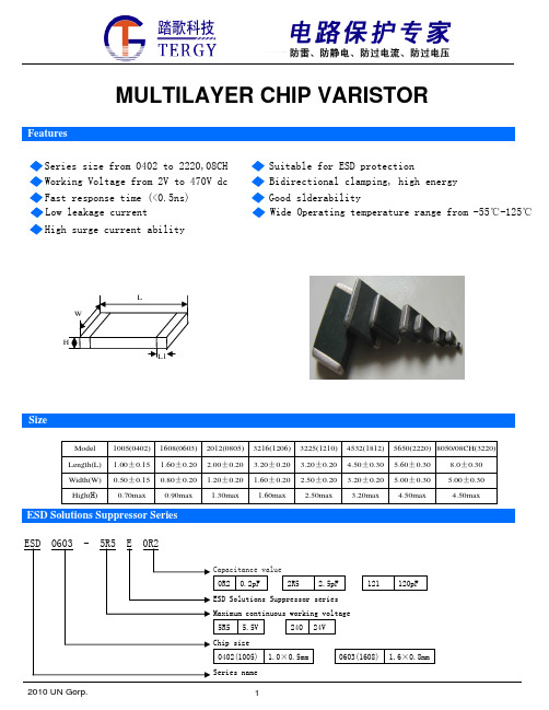
贴片压敏电阻0603封装参数型号规格书大全
18
45
ESD0402-5R5E220
5.5
45
0402
ESD0402-140E330
14
45
ESD0402-5R5E500
5.5
45
ESD0402-120E101
12
40
ESD0402-120E131
12
40
ESD0402-140E161
14
35
ESD0402-9R0E181
9
30
ESD0402-5R5E481
varistor voltage shall be within 10%.
The temperature cycle of specified Step
Temperature
Period
temperature shall be repeated five times and 1
-40±3℃
30min±3
2010 UN Gorp.
9
Packaging Specification
Carrier tape transparent cover tape should be heat-sealed to carry the products, and the reel should be used to reel the carrier tape.
3
125±2℃
30min±3
mechanical damage shall be examined.
4 Room Temperature 1~2hours
After being continuously applied the maximum allowable voltage at 85℃ for High Temperature Load 1000hours, the specimen shall be stored at room temperature and humidity for one or
国巨压敏电阻产品0402-0603两型号

VR
0402 / 0603
5.5 V to 38 V
CONSTRUCTION Lead Free terminations, NiSn terminations Surface mount multilayer surge suppressor Very short response time (<1.0 nsec) Bidirectional clamping Low capacitance for high frequency applications Very low leakage current
VARISTOR/ MAX. WORKING CLAMPING PEAK LEAKAGE CURRENT BREAKDOWN VOL. VOL.@1A CURRENT R.T. (15~35 °C) VOL. DC @1mA D.C (max.) 8/20 µS (max.) 8/20 µS (max.) Voltage Current
ORDERING INFORMATION - GLOBAL PART NUMBER, PHYCOMP CTC & 12NC All part numbers are identified by the series, size, tolerance, TC material, packing style, voltage, process code, termination and capacitance value. YAGEO BRAND ordering code GLOBAL PART NUMBER (PREFERRED )
10 V ~ 14 V 10 V ~ 14 V 10 V ~ 14 V 10 V ~ 14 V 7.2 V ~ 10.8 V 7.2 V ~ 10.8 V 7.2 V ~ 10.8 V 7.2 V ~ 10.8 V 7.2 V ~ 10.8 V 7.2 V ~ 10.8 V 10.8 V ~ 13.2 V 10.2 V ~ 13.8 V 10.2 V ~ 13.8 V 18 V ~ 24 V 18 V ~ 24 V 18 V ~ 24 V 14.4 V ~ 21.6 V 16.2 V ~ 19.8 V 90 V ~ 135 V 50 V ~ 80 V 50 V ~ 80 V 24 V ~ 34 V 24 V ~ 34 V 24 V ~ 34 V 24 V ~ 34 V 24 V ~ 34 V 24 V ~ 34 V 21.6 V ~ 26.4 V 24 V ~ 34 V 27 V ~ 38 V 50 V ~ 80 V 5.5 V 5.5 V 5.5 V 5.5 V 5.5 V 5.5 V 5.5 V 5.5 V 5.5 V 5.5 V 9V 9V 9V 14 V 14 V 14 V 14 V 14 V 18 V 18 V 18 V 18 V 18 V 18 V 18 V 18 V 18 V 18 V 18 V 19 V 30 V 22 V 22 V 22 V 22 V 18 V 18 V 18 V 18 V 18 V 18 V 22 V 22 V 22 V 38 V 38 V 38 V 35 V 33 V 250 V 130 V 130 V 66 V 66 V 66 V 66 V 66 V 66 V 56 V 66 V 60 V 130 V 2A 4A 6A 10 A 10 A 15 A 15 A 20 A 20 A 30 A 6A 6A 15 A 7A 15 A 15 A 20 A 20 A 1A 1A 2A 3A 3A 3A 4A 4A 4A 10 A 15 A 15 A 1A 5.5 V 5.5 V 5.5 V 5.5 V 5.5 V 5.5 V 5.5 V 5.5 V 5.5 V 5.5 V 9V 9V 9V 14 V 14 V 14 V 14 V 14 V 18 V 18 V 18 V 18 V 18 V 18 V 18 V 18 V 18 V 18 V 18 V 19 V 18 V 10 µA 10 µA 10 µA 10 µA 10 µA 10 µA 10 µA 10 µA 10 µA 10 µA 20 µA 20 µA 20 µA 20 µA 20 µA 20 µA 20 µA 20 µA 10 µA 10 µA 10 µA 10 µA 10 µA 10 µA 10 µA 10 µA 10 µA 35 µA 10 µA 4 µA 10 µA
耐冲击电阻 0603

耐冲击电阻 0603电子产品现在已经成为人们生活中不可或缺的一部分,而耐冲击电阻0603作为其中的重要组件之一,起着至关重要的作用。
它能够保护电路免受外界冲击和干扰,确保电子设备的正常运行。
本文将对耐冲击电阻0603的特点和应用进行详细阐述。
一、耐冲击电阻0603的特点耐冲击电阻0603采用了先进的制造技术和材料,具有以下几个主要特点:1. 小巧精致:耐冲击电阻0603的尺寸仅为0.06英寸×0.03英寸(即1.6毫米×0.8毫米),体积非常小巧。
这使得它能够在电路板上占用更少的空间,为其他元件留出更多的空间,有利于电路的设计和布局。
2. 高耐冲击能力:耐冲击电阻0603采用了耐压材料制作而成,能够承受较大的冲击和振动,不易受到外界环境的干扰。
这使得电子设备能够在恶劣的环境中长时间运行,保证产品的可靠性和稳定性。
3. 低电阻值:耐冲击电阻0603具有较低的电阻值,能够提供稳定的电流传输和热量分散。
这对于电路的正常运行至关重要,能够有效地减少电流紊乱和电器设备发热的问题。
4. 宽温度范围:耐冲击电阻0603能够在较宽的温度范围内工作,通常从-55℃到+155℃。
这使得它非常适用于各种环境温度变化较大的场合,例如汽车电子、航空航天等领域。
二、耐冲击电阻0603的应用领域耐冲击电阻0603由于其优异的特点,在各个领域都有广泛的应用。
以下是它的几个主要应用领域:1. 通信设备:耐冲击电阻0603在手机、平板电脑、路由器等通信设备中扮演重要的角色。
它可以确保信号的传输稳定,提高通信质量,减少干扰和噪音,保证通信设备顺利运行。
2. 汽车电子:耐冲击电阻0603广泛应用于汽车电子系统中,如发动机控制单元(ECU)、制动系统、导航系统等。
它能够保护电子设备不受汽车震动和冲击的影响,提高整个汽车电子系统的可靠性和稳定性。
3. 工业控制:耐冲击电阻0603在工业控制设备中起着重要作用,用于保护设备免受电磁干扰和电压冲击的影响。
0603元件标准封装的含义和用途
0603元件标准封装的含义和用途一、0603元件标准封装的含义0603元件标准封装是一种常见的电子元件封装形式,其尺寸符合JEDEC(电子设备工程联合委员会)的标准。
具体来说,0603元件标准封装的长度为0.6英寸,宽度为0.3英寸,是一种非常紧凑的封装形式。
这种封装常用于贴片式电阻器、电容器、二极管等电子元件,是现代电子制造中不可或缺的一部分。
二、0603元件标准封装的特点1.尺寸小巧:0603元件标准封装具有较小的体积,可以有效地减少电路板的占用空间,方便实现小型化和轻量化设计。
2.集成度高:由于封装尺寸较小,可以在相对较小的区域内集成更多的电子元件,从而提高电路的性能和稳定性。
3.可靠性高:0603元件标准封装采用了可靠的焊接技术和封装材料,可以保证电子元件在各种环境条件下稳定工作。
4.成本效益高:这种封装形式制造成本较低,能够满足大规模生产的需求,有利于降低电子产品整体成本。
三、0603元件标准封装的优势1.高性能:0603元件标准封装能够提供较高的电气性能,有利于实现高速、高精度的电子信号传输。
2.灵活性:这种封装形式适用于各种不同的电子元件,可以根据不同的应用需求进行定制化设计。
3.兼容性强:0603元件标准封装与各种不同的电路板和焊接技术兼容,可以方便地与其他电子元器件配合使用。
4.长寿命:由于其采用的焊接技术和封装材料具有良好的耐久性,因此可以保证电子元件在使用期间内具有较长的使用寿命。
四、0603元件标准封装的应用领域1.消费电子产品:在智能手机、平板电脑、笔记本电脑等消费电子产品中,0603元件标准封装被广泛应用于各种小型化、高性能的电路板制造中。
2.通信设备:在无线通信设备、基站、路由器等通信设备中,由于需要实现高速信号传输和处理,0603元件标准封装成为重要的组成部分。
3.汽车电子:在汽车电子领域中,由于汽车对可靠性和安全性的要求较高,0603元件标准封装以其高可靠性和长寿命等特点而被广泛应用于各种车载电子系统中。
台湾viking薄膜0603x4贴片排阻TFAN系列选型手册

Ambient Temperature(℃)
■Electrical Specifications
Item Type TFAN 43 Power Rating at 70°C 1/16W Operating Temp. Range -55 ~ +155°C Max. Operating Voltage 50V Max. Overload Voltage 100V Resistance Range ±0.1% ±0.25% 100Ω~33KΩ ±0.5% TCR (PPM/°C) ±25 ±50
Accuracy Grade Table Code B0 B3 C0 C2 C3 D0 D1 D2 F0 F1 Tolerance Grade Absolute Tolerance Tolerance Matching ±0.1% N/A ±0.1% 0.1% ±0.25% N/A ±0.25% 0.25% ±0.25% 0.1% ±0.5% N/A ±0.5% 0.5% ±0.5% 0.25% ±1% N/A ±1% 0.5% Rsistance Value 100~33K 100~33K 100~33K 100~33K 100~33K 100~33K 100~33K 100~33K 100~33K 100~33K Code B0 B3 N0 N3 C0 C2 C3 D0 D1 D2 TCR Grade Absolute TCR TCR Tracking ±10ppm N/A ±10ppm 15ppm ±15ppm N/A ±15ppm 15ppm ±25ppm N/A ±25ppm 25ppm ±25ppm 15ppm ±50ppm N/A ±50ppm 50ppm ±50ppm 25ppm Rsistance Value 100~2K 100~2K 100~2K 100~2K 100~33K 100~33K 100~33K 100~33K 100~33K 100~33K
0603贴片电容封装尺寸
0603贴片电容封装尺寸1. 背景介绍贴片电容是一种常见的电子元件,用于存储和释放电荷。
它广泛应用于电子产品中,例如手机、平板电脑、计算机等。
贴片电容的封装尺寸是指其外形尺寸,包括长度、宽度和高度等参数。
在电子产品设计中,正确选择合适的贴片电容封装尺寸非常重要,因为它直接影响到元件的性能和整体产品的可靠性。
2. 贴片电容封装尺寸标准贴片电容的封装尺寸通常遵循国际标准。
目前,最常见的贴片电容封装标准是EIA-0402、EIA-0603、EIA-0805等。
其中,本文将重点介绍EIA-0603贴片电容的封装尺寸。
EIA-0603标准规定了贴片电容的外形和引脚布局。
根据该标准,EIA-0603贴片电容的外形尺寸为0.063英寸(1.6毫米)长、0.031英寸(0.8毫米)宽。
这种标准化设计使得EIA-0603贴片电容在不同厂家之间具有互换性,方便了电子产品的设计和制造。
除了外形尺寸外,EIA-0603贴片电容还有一些其他重要的封装参数。
例如,引脚间距一般为0.03英寸(0.8毫米),引脚长度为0.02英寸(0.5毫米)。
这些参数对于PCB布局和焊接工艺有着重要的影响。
3. 贴片电容封装尺寸的选择正确选择合适的贴片电容封装尺寸对于电子产品设计至关重要。
以下是一些选择贴片电容封装尺寸的考虑因素:3.1 空间限制在设计紧凑型电子产品时,空间通常是一个关键因素。
较小的贴片电容封装可以帮助节省宝贵的空间。
然而,过小的封装也可能导致焊接难度增加和热量分散问题。
3.2 电流需求不同封装尺寸的贴片电容可以承受不同的最大工作电流。
在选择时,需要根据具体应用场景和系统需求来确定所需的工作电流范围,并选择合适的贴片电容封装尺寸。
3.3 频率特性贴片电容的频率特性也是一个重要考虑因素。
较小封装的贴片电容通常具有更好的高频响应能力,适用于高频应用。
而较大封装的贴片电容则更适合低频应用。
3.4 成本不同尺寸的贴片电容在制造成本上可能存在差异。
贴片电阻、贴片电容规格、封装、尺寸、功率
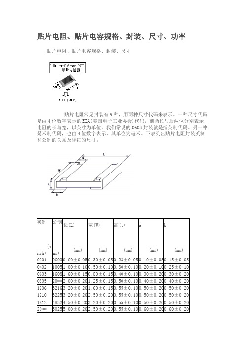
贴片电阻、贴片电容规格、封装、尺寸、功率贴片电阻、贴片电容规格、封装、尺寸贴片电阻常见封装有9种,用两种尺寸代码来表示。
一种尺寸代码是由4位数字表示的EIA(美国电子工业协会)代码,前两位与后两位分别表示电阻的长与宽,以英寸为单位。
我们常说的0603封装就是指英制代码。
另一种是米制代码,也由4位数字表示,其单位为毫米。
下表列出贴片电阻封装英制和公制的关系及详细的尺寸:贴片电容和贴片电阻都是一样可以用的,0805,1206等贴片电阻电容功率与尺寸对应表电阻封装尺寸与功率关系,通常来说:0201 1/20W0402 1/16W0603 1/10W0805 1/8W1206 1/4W电容电阻外形尺寸与封装的对应关系是:0402=1.0x0.50603=1.6x0.80805=2.0x1.21206=3.2x1.61210=3.2x2.51812=4.5x3.22225=5.6x6.5常规贴片电阻(部分)常规的贴片电阻的标准封装及额定功率如下表:英制(mil) 公制(mm) 额定功率(W)@ 70°C0201 0603 1/200402 1005 1/160603 1608 1/100805 20** 1/81206 3216 1/41210 3225 1/31812 4832 1/220** 5025 3/42512 6432 1国内贴片电阻的命名方法:1、5%精度的命名:RS-05K102JT2、1%精度的命名:RS-05K1002FTR -表示电阻S -表示功率0402是1/16W、0603是1/10W、0805是1/8W、1206是1/4W、 1210是1/3W、1812是1/2W、20**是3/4W、2512是1W。
05 -表示尺寸(英寸):02表示0402、03表示0603、05表示0805、06表示1206、1210表示1210、1812表示1812、10表示1210、12表示2512。
- 1、下载文档前请自行甄别文档内容的完整性,平台不提供额外的编辑、内容补充、找答案等附加服务。
- 2、"仅部分预览"的文档,不可在线预览部分如存在完整性等问题,可反馈申请退款(可完整预览的文档不适用该条件!)。
- 3、如文档侵犯您的权益,请联系客服反馈,我们会尽快为您处理(人工客服工作时间:9:00-18:30)。
Document Number: 34179For technical questions, contact: magnetics@
Revision: 10-Aug-06
89
IFCB-0603
Vishay Dale
Thin Film Chip Inductor
FEATURES
•Tight tolerance
•Self-resonant frequency controlled within 10 %•Stable inductance over high frequencies •Compatible with reflow or flow soldering •100 % lead (Pb)-free and RoHS compliant
•
Temperature range: - 40 °C to + 125 °C (no load)
- 40 °C to + 85 °C (full rated current)
APPLICATIONS
•Cellular telephone, pagers and GPS products
•Wireless LAN and other communication appliances •VCO, TCXO circuit and RF transceiver module
STANDARD ELECTRICAL SPECIFICATIONS
L 500 MHz (nH) L TOL. Q 100 MHz (Typ.) Q 800 MHz (Typ.) Q 1700 MHz (Typ.)
SRF MHz (Typ.) DCR Ohms (Max.) RATED DC CURRENT
(mA)
1.0 1.2 1.5 1.8
2.2 2.7
3.3 3.9
4.7
5.6
6.8 8.2 10 12 15 18 22 27 33 39 47 56 68
0.3 nH 0.3 nH 0.3 nH 0.3 nH 0.3 nH 0.3 nH 0.3 nH 0.3 nH 0.3 nH 0.3 nH 0.3 nH 0.3 nH 2 %, 5 %2 %, 5 % 2 %, 5 %2 %, 5 %2 %, 5 % 2 %, 5 %2 %, 5 %2 %, 5 %2 %, 5 %2 %, 5 %2 %, 5 %
13 13 13 13 13 13 13 13 13 13 13 13 13 13 13 13 13 10 10 10 10 10 10
34 34 34 34 34 34 34 34 34 34 34 34 34 30 30 30 30 45 45 45 45 26 26
49 49 49 49 49 49 49 49 41 41 41 41 30 30 30 25 25 25 6 1 1 4 6
13 000 13 000 10 000 10 000 8000 6000 6000 6000 5000 5000 5000 4000 4000 3000 3000 2000 2000 2000 1500 1500 1500 1000 1000
0.35 0.35 0.35 0.35 0.35 0.45 0.45 0.45 0.55 0.65 0.75 0.95 0.95 1.05 1.35 1.65 1.95 2.35 2.75 3.0 3.0 5.0 5.0
800 800 800 300 300 300 300 300 300 300 300 300 300 300 300 300 250 250 250 200 200 150 150
元器件交易网
Document Number: 91000
Revision: 18-Jul-08
1
Disclaimer
Legal Disclaimer Notice
Vishay
All product specifications and data are subject to change without notice.
Vishay Intertechnology, Inc., its affiliates, agents, and employees, and all persons acting on its or their behalf (collectively, “Vishay”), disclaim any and all liability for any errors, inaccuracies or incompleteness contained herein or in any other disclosure relating to any product.
Vishay disclaims any and all liability arising out of the use or application of any product described herein or of any information provided herein to the maximum extent permitted by law. The product specifications do not expand or otherwise modify Vishay’s terms and conditions of purchase, including but not limited to the warranty expressed therein, which apply to these products.
No license, express or implied, by estoppel or otherwise, to any intellectual property rights is granted by this document or by any conduct of Vishay.
The products shown herein are not designed for use in medical, life-saving, or life-sustaining applications unless otherwise expressly indicated. Customers using or selling Vishay products not expressly indicated for use in such applications do so entirely at their own risk and agree to fully indemnify Vishay for any damages arising or resulting from such use or sale. Please contact authorized Vishay personnel to obtain written terms and conditions regarding products designed for such applications.
Product names and markings noted herein may be trademarks of their respective owners.
元器件交易网。