TSOP2240UH1中文资料
HA12240FP中文资料

VCC VIN Vbus
7
V
GND–0.3 to VCC+0.3
V
18
V
Allowable power dissipation
Pd
400
mW
Operating temperature
Topr
–40 to +85
°C
Storage temperature
Tstg
–55 to +125
°C
Note: Recommended operating power supply voltage range: 5 V ± 0.5 V
(Ta = 25°C) Note
Ta ≤ 85°C
Electrical Characteristics
(VCC = 5.0 V, Ta = 25°C)
Test Test
Item
Symbol Min Typ Max Unit Test Conditions
Pin Circuit
S1
High-level input voltage VIHS1
Pin Circuit
Receiver High-level input voltage VIH1 (1)
— 80 110 mV V6 = 0→5 V, Pin2 = 4 V or more, 2 V1 = 0 V, V3 = 0 V, V5 = 0 V,
Fig. 2
High-level input voltage VIH2 (2)
2.1 — — V V1 = 0→5 V, V3 = 0 V,
V6 – V5 = 110 mV↑
1
Fig. 1
Low-level input voltage VILS1
Eaton公司产品说明书:预置电子封闭体与水平面板

Horizontal panelsThe pre-configured enclosures are equipped withsingle-piece, full depth panels installed in the top of theenclosure.Single-piece horizontal panelHorizontal panel “flip-over” featureWhen used as top panels, the horizontal panels may be installed with the smooth side up or down. Installing the panel with the smooth side down helps minimize cold air bypass over the top of the electronic equipment zone, particularly in the front of the enclosure. This mode of installation is also useful to create a front-to-back cable chase over the top exterior of the enclosure.Single-piece horizontal panel (inverted)800mm wide enclosure with removablebrushesRS Horizontal panels (top)DISCLAIMER OF WARRANTIES AND LIMITATION OF LIABILITYThe information, recommendations, descriptions and safety notations in this document are based on Eaton Corporation’s (“Eaton”) experience and judgment and may not cover all contingencies. If further information is required, an Eaton sales office should be consulted. Sale of the product shown in this literature is subject to the terms and conditions outlined in appropriate Eaton selling policies or other contractual agreement between Eaton and the purchaser.THERE ARE NO UNDERSTANDINGS, AGREEMENTS, WARRANTIES, EXPRESSED OR IMPLIED, INCLUDING WARRANTIES OF FITNESS FOR A PARTICULAR PURPOSE OR MERCHANTABILITY , OTHER THAN THOSE SPECIFICALL Y SET OUT IN ANY EXISTING CONTRACT BETWEEN THE PARTIES. ANY SUCH CONTRACT STATES THE ENTIRE OBLIGATION OF EATON. THE CONTENTS OF THIS DOCUMENT SHALL NOT BECOME PART OF OR MODIFY ANY CONTRACT BETWEEN THE PARTIES. In no event will Eaton be responsible to the purchaser or user in contract, in tort (including negligence), strict liability or otherwise for any special, indirect, incidental or consequential damage or loss whatsoever, including but not limited to damage or loss of use of equipment, plant or power system, cost of capital, loss of power, additional expenses in the use of existing power facilities, or claims against the purchaser or user by its customers resulting from the use of the information, recommendations and descriptions contained herein. The information contained in this manual is subject to change without notice.How to remove and install a horizontal panelHorizontal panels are retained by M6 thread forming hex head bolts.To remove a horizontal panel:1 Loosen bolts about 1/2 way. 2 Lift panel up and off bolts.3To install panel in inverted position, remove bolts completely, invert panel align and secure bolts with oval cut outs. (will require access to cabinet from top to secure)Note: Reverse procedure to flip or reinstall panels.600How to remove and install a horizontal panel – 800 mm wide enclosuresHorizontal panels for 800 mm wide enclosure consist of additional side brushes that fill the roughly 100 mm gap on ether side of the enclosure. To remove these panels:Slide brushes off top edges of inner front top back channels.Note : Remove inner panel(s) the same as noted previously.Note : Reverse procedure to reinstall panels or flipinner panel(s).800RS HORIZONTAL PANELSEaton1000 Eaton Boulevard Cleveland, OH 44122United States © 2018 EatonAll Rights Reserved Printed in USAPublication No. IL159004EN October 2018Eaton is a registered trademark.All trademarks are property of their respective owners.Follow us on social media to get thelatest product and support information.。
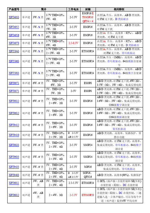
矽普特产品简介
XPT5983 XPT9971 XPT8871 XPT9812
XPT9612
XPT9412 XPT9410 XPT9833
XPT9633 XPT9433 XPT9403 XPT6011
XPT6012
道(双声道)提供4W 平均功率
产品型号 XPT6013 XPT6871 XPT6875 XPT4809
XPT9863
XPT8863
XPT2008
XPT2069
XPT2068 C
XPT4098 XPT4871
F XPT4890 XPT4990 XPT0030 XPT4066 XPT4088 XPT4068 XPT6872
4 SOP18/SS OP24/SOP
16
SOP16/QF N16/DIP16 MSOP8/SO P8/ESOP8/
DFN8 MSOP8/SO
P8/DFN
WCSP9
MSOP8/ES OP8/SOP8/
DFN
WCSP
备注 单端模式,5V,THD+N≤0.5%,75mW (32Ω)。XPT4963的 SD 是高电平工作,
封装
ETSSOP20
SOP8
ESOP8
MSOP8/SO P8
SOP16/DIP 16/ETSSO P16/ETSS OP20 SOP16/ET SSOP20/DI P16
SOP8/ ESOP8
SOP16/DIP 16/ESOP16
SOP16/ES OP16/DIP1
6
QFN16/SO P16/DIP16
完全兼容 LM4861/8002 ,XPT4871H
Eaton 退火保护设备 RSP 系列用户手册说明书

ContentsDescription Page Applications . . . . . . . . . . . . . . . . . . . . . . . . . . . . . .2Features . . . . . . . . . . . . . . . . . . . . . . . . . . . . . . . . .2Standards and certifications . . . . . . . . . . . . . . . . .2VPR performance data . . . . . . . . . . . . . . . . . . . . .2Dimensions in inches (mm) . . . . . . . . . . . . . . . . . .3RSP configuration guide . . . . . . . . . . . . . . . . . . . .4Specifications . . . . . . . . . . . . . . . . . . . . . . . . . . . .4Mounting provisions . . . . . . . . . . . . . . . . . . . . . . .4IntroductionEaton’s retrofit surge protective (RSP) series consists of UL ® 1449 5th Edition-listed surge protective devices (SPD) that provide a reliable, cost-effective, aftermarket solution for surge protection . Designed for easy installation, this Type 1 or Type 2 SPD is approved for field installation and is capable of easy installation directly into a panelboard or switchboard without any modifications . The RSPF is available in multiple configurations that are specifically designed for Eaton panelboards and switchboards, allowing for installation on systems utilizing most common voltages . Easy mounting options coupled with a compact footprint enable quick installation of the RSPF in panelboards and switchboards in less than 10 minutes .Retrofit F-/PD2-frame,surge protective deviceF-/PD2-frame2Technical Data TD158032ENEffective September 2023Retrofit F-/PD2-frame, surge protective deviceEATONApplicationsThe Eaton RSPF series SPD protects critical electrical and electronic equipment from damage caused by voltage transients and surges when properly installed . This is done by shunting high-energy lightning surges (and other transient disturbances) away from the equipment being protected . It does this in nanoseconds by providing a low impedance surge path to ground through thermally protected metal oxide varistors while supporting power frequency voltage . The Eaton RSPF series SPD was designed solely for aftermarket applications and developed to fit in the space of an EatonF-/PD2-frame molded case circuit breaker . The RSPF is intended for retrofit into existing panelboards or switchboards with space or provisions for the F-/PD2-frame size .Features• Voltage ratings from 208 Vac to 600 Vac• Uses thermally protected metal oxide varistor (MOV) technology • LED protection status indicators•20 kA nominal discharge current (I n ) rating (maximum rating in the UL 1449 5th Edition standard)•F-/PD2-frame molded case circuit breaker footprint for ease of installation• Compact footprint—6 .00 L x 4 .13 W x 3 .69 D inches • Direct bus mounting • 2-year warranty• 50 kA and 100 kA per phase surge current capacity•No user-serviceable parts or items requiring periodic maintenanceStandards and certifications• UL 1449 5th Edition Type 1 and Type 2•Tested to UL 1283 7th EditionDesigned and tested in accordance with the latest versions of these standards:• IEEE ® C62 .41 .1• IEEE C62 .41 .2• IEEE C62 .43• IEEE C62 .45• IEEE C62 .48•IEEE C62 .62VPR performance dataT able 1. Voltage protection ratingsModelApplicationVoltageVPRL–G / L–NL–LRSPF240MA 120/208Y 900900127/220Y 900900240D 900900SA 120/208Y 12001000127/220Y 12001000240D 12001000SB120/208Y 900900127/220Y 900900240D 900900RSPF480MA480D 180********/22018001800400/23018001800415/24018001800480/27718001800SA480D 20002000380/22020002000400/23020002000415/24020002000480/27720002000SB480D 180********/22018001800400/23018001800415/24018001800480/27718001800RSPF600MA 600D 25002500600/34725002500SA 600D 25002500600/34725002500SB 600D 25002500600/347250025003Technical Data TD158032ENEffective September 2023Retrofit F-/PD2-frame, surge protective device EATON Dimensions in inches (mm)Figure 1. RSPF dimensionsEaton1000 Eaton Boulevard Cleveland, OH 44122United States Eaton .com© 2023 EatonAll Rights Reserved Printed in USAPublication No . TD158032EN / Z27894September 2023Eaton is a registered trademark.All other trademarks are property of their respective owners.Retrofit F-/PD2-frame, surge protective deviceTechnical Data TD158032ENEffective September 2023SpecificationsT able 2. SpecificationsDescriptionRatingskA per phase50 (on units with filtering), 100Nominal discharge current 20 kASystem voltages 240 V rated models: 208Y, 220Y, 240D480 V rated models: 380Y, 400Y, 415Y, 480Y, 480D 600 V rated models: 600Y, 600D Input power frequency 50/60 HzProtection modes Wye L-N or L-G, L-L Delta L-G, L-L Short-circuit current rating (SCCR)200 kAOperating temperature –40 ºC to +60 ºCRelative humidity 5%–95%, noncondensing Maximum altitude 2000 m Weight3.0 lbCertification/listing UL 1449 5th Edition, CSA ® 269.1-14, 269.2-15,C22.2 No. 8-13 EMI filter a Tested to 1283 7th Edition SPD typeType 1 and Type 2RoHS compliant YesEnclosure ratingType 1 enclosure, IP40Maximum continuousoperating voltage (MCOV) b 300 L-L, L-G—240 V RSPF2403MA1A, RSPF2403SA2A, RSPF2403SB1A 640 L-L, L-G—480 V RSPF4803MA1A, RSPF4803SA2A, RSPF4803SB1A 840 L-L, L-G—600 VRSPF6003MA1A, RSPF6003SA2A, RSPF6003SB1Aa Available only with SA option.b MCOV ratings are the same for units with or without a provision kit selected.RSP configuration guidea Available only with SB and MA options.b Available only with SA option.Technical support informationFor questions or additional information, please contact the Eaton Technical Resource Center at 1-800-809-2772, option 5, option 2.You may submit inquiries via email to *************and find more information at /rspMounting provisionsKit contains A, B, and C phase connectors, hardware, and instruction to mount three-pole RSPF surge devices .KPRL4FDKPRL3AFD3。
Emotron TSA软启动器技术目录说明书
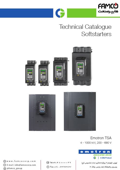
Technical CatalogueSoftstartersEmotron TSA4 - 1000 kW, 200 - 690 VEmotron TSA softstarter - with built-in bypass16 - 56 A 70 - 100 A 140 - 200 A 240 - 450 A 470 - 820 A835 - 960 AEmotron TSA softstarters take motor control to a new level. Soft torque starting, intelligent load monitoring and smart stops are all included and accompanied by a robust and compact design. By developing the Emotron TSA range of electronic softstarters CG has taken a major step towards the ideal motor controller for applications where variable speed is not required. You simply get everything except variable speed!Main features • Compact and robust softstarter with wide power range:4kW - 1000 kW, 200 - 690V, 3 ph.•Integrated bypass with proven contactor technology (TSA sizes 1 - 5).•3-phase torque control for optimal performance.•Torque control start and stop modes for smooth low-current starts and pump stops without water hammering.•High capacity dynamic vector braking available for high inertia stopping.•Coated boards as standard extends lifetime in harsh environments.•Real-time clock.•Multilingual control panel. Supports parameter copying between units.•Jog forward/reverse with adjustable speed.•Motor I 2t protection and isolated thermistor input as standard. PT100 inputs as option.•Load monitor function for protection of your load machinery.•Logic and timer programming blocks available.•IP20 protection for sizes 16-960 A.•Fulfills EMC First environment-category C2.•UL/cUL approvals.• DNV-GL marine approval.TSA 1TSA 2TSA 3TSA 4TSA 5TSA 6EMOTRON TSAEMOTRON TSA Emotron TSA softstarterTypical motor power at mains voltage 400 V and 460 VRating according to AC53b / AC3A norm., Start time = 15 s (size 1) or 30 s (Size 2 - 4), 10 starts / hour.n.soft(2) Heavy duty: Start current = 5 x I, Start time = 15 s (size 1) or 30 s (Size 2 - 4), 10 starts / hour.n.soft(3) H1= Height of enclosure, H2=Total height(4) Normal duty: Start current = 3 x InStart time = 30 s, 4 starts / hour, utilization=80 % - size 5, 70 % - size 6..soft,(5) Heavy duty: Start current = 5 x I, Start time = 30 s, 4 starts / hour, utilization=80 % - size 5, 70 % - size 6.n.soft(6) With external bypass contactor.EMOTRON TSATypical motor power at mains voltage 525 VRating according to AC53b / AC3A norm.(1) Normal duty: Start current = 3 x I n.soft , Start time = 15 s (size 1) or 30 s (Size 2 - 4), 10 starts / hour.(2) Heavy duty: Start current = 5 x I n.soft , Start time = 15 s (size 1) or 30 s (Size 2 - 4), 10 starts / hour.(3) H1= Height of enclosure, H2=Total height(4) Normal duty: Start current = 3 x In .soft, Start time = 30 s, 4 starts / hour, utilization=80 % - size 5, 70 % - size 6.(5) Heavy duty: Start current = 5 x I n.soft , Start time = 30 s, 4 starts / hour, utilization=80 % - size 5, 70 % - size 6.(6) With external bypass contactor.Typical motor power at mains voltage 575 V and 690 V Rating according to AC53b / AC3A norm.(1) Normal duty: Start current = 3 x I n.soft , Start time = 15 s (size 1) or 30 s (Size 2 - 4), 10 starts / hour.(2) Heavy duty: Start current = 5 x I n.soft , Start time = 15 s (size 1) or 30 s (Size 2 - 4), 10 starts / hour.(3) H1= Height of enclosure, H2=Total height(4) Normal duty: Start current = 3 x In .soft, Start time = 30 s, 4 starts / hour, utilization=80 % - size 5, 70 % - size 6.(5) Heavy duty: Start current = 5 x I n.soft , Start time = 30 s, 4 starts / hour, utilization=80 % - size 5, 70 % - size 6.(6) With external bypass contactor.EMOTRON TSASPECIFICATIONS* see Emotron TSA instruction manual chapter 13 for details.General specificationsGeneralEnvironmental conditionsSPECIFICATIONS Operation at higher temperaturesThe Emotron softstarter is made for operating at maximum 40°C ambient temperature.However, it is possible to use Emotron softstarter at higher temperatures with reduced output current rating (derating). Table 1 shows ambient temperatures as well as possible derating for higher temperatures.T able 1 Ambient temperature and possible deratingDimensions and weightsThe table below gives an overview of the dimensions, weights, cooling and mounting.H1 = Enclosure heightH2 = Total height including cable interface1) For max 1 % inaccuracy.See “User interface data” on page 9 for connection data and default settings.Basic I/O dataSPECIFICATIONSRecommended load fuseRecommended slow fuses (type gG) for protection against overload.Semiconductor fuses, TSA frame sizes 1 - 4SPECIFICATIONS Ultrarapid fuses, TSA frame sizes 5 - 6User interface dataEmotron TSANameFunction (Default)Control board terminals11DigIn 1Run FWD 12DigIn 2Stop1310 VDC Supply voltage for analogue input 14AnIn Process value15GND Signal ground (Common)16DigIn 3Set Ctrl 117DigIn 4Reset18+24 V +24 VDC Supply voltage 19AnOut 0 to motor nom. current 20+24 V+24 VDC Supply voltage Power board terminals PEProtective Earth N Control supply voltage 100 - 240 VAC ± 10%L 21Relay 1NO Operation 22C 23Relay 2NO Not used24C 31Relay 3NO Trip32C 33NC69PTC thermistor input (isolated)70*) Default selectionSPECIFICATIONSAll analogue and digital inputs andoutputs are programmable.OPTIONS Standard options for Emotron TSASupport for 2 option boards plus 1 communication option.I/O board3 extra relay outputs (230 VAC/5 ANO/NC). 3 extra 24 V /3.2 kΩ (AC orDC) differential digital inputs, allprogrammable. Inputs providing50 VAC/DC isolation betweenchannels.Maximum 2 I/O boards can bebuilt -in per TSA softstarter.Part no. 01-3876-51PTC/PT100 board1 PTC isolated input conforming DIN44081/44082.Max 6 PTC thermistors can beconnected in series to PTC input.Also including 3 PT100 inputs,2/3/4-wire, conforming EN 60751.Maximum 2 PTC/PT100 boards canbe built -in per TSA softstarterPart no. 01-3876-58Fieldbus - ProfibusFieldbus option module for ProfibusDP or DP V1 communication. Use9-pin D-sub connector.Baud rates: 9.6 kbits/s - 12 Mbits/ssupported.Typical TSA response time = 10 ms(not including any fieldbus delays).Part no. 01-5385-55Fieldbus - DeviceNetFieldbus option module forDeviceNet communication.Baud rates: 125 - 500 kbits/ssupported.Typical TSA response time = 10 ms(not including any fieldbus delays).Part no. 01-5385-56Ethernet - Modbus / TCPIndustrial Ethernet option module forModbus/TCP protocol. RJ45 typeconnector.Baud rates: 10 or 100 Mbits/ssupported.Typical TSA response time = 10 ms(not including any ethernet delays).Part no. 01-5385-59OPTIONSEthernet - EtherCATIndustrial Ethernet option module for EtherCAT protocol.Baud rate: 100 Mbits/sTypical TSA response time = 10 ms (not including any Ethernet delays).Part no. 01-5385-60Ethernet - Profinet IO 1-portIndustrial Ethernet option module for Profinet IO (RT) protocol.Baud rate: 100 Mbits/sTypical TSA response time = 10 ms (not including any Ethernet delays).Part no. 01-5385-61Ethernet - Profinet IO 2-portIndustrial Ethernet option module for Profinet IO (RT) protocol.Baud rate: 100 Mbits/sTypical TSA response time = 10 ms (not including any Ethernet delays).Part no. 01-5385-62USB isolatedIsolated USB serial communication module. For Modbus RTU comm.protocol.Baude rates: 2.4 - 115.2 kbits/s supported.Typical TSA response time = 10 msPart no. 01-5385-63RS485 isolatedIsolated RS485 serialcommunication module. For Modbus RTU comm.protocol.Baude rate: 2.4 - 115.2 kbits/s supported.Typical TSA response time = 10 msPart no. 01-5385-54External control panelExternal control panel IP54 suitable for mounting on a cabinet door. Kit complete with control panel,mounting frame and 3 m cable.EmoSoftComConnect a PC with a standard RS232 cable to D-sub on top of TSA unit or via USB/RS485 /Modbus - TCP Comm. modules (Optional).EmoSoftCom PC software makes it possible to perform signal recordingsand save/load parameter backup data, for example during service &maintenance.OPTIONSFieldbus - CANopenFieldbus option module for CANopen communication. Use 9-pin D-sub connector.Baud rates 10 kbit/s - 1 Mbits/sKit of external current transducers and cables for TSA size 6Set of 2 current transducers for TSA size 6, if using external bypass contactor. Also includes extension cables for CT connection to TSA unit.Fieldbus - EtherNetIPIndustrial Ethernet option module for Profinet IO (RT) protocol. 1 x RJ45type connector.Baud rate: 100 Mbits/sTypical TSA response time = 10 ms (not including any fieldbus delays).Part no. 01-5385-64Part no. 01-5385-65Part no. 01-5406-00Part no. 01-7802-002D and 3D CAD drawings for Emotron AC drives,website. These will assist anyone working withour products, for example, consultants, installersor machine builders.Visit for direct access to allCAD documents.D r i v e s & A u t o m a t i o n . 01-5552-01r 3E n g l i s h , 2023-01-18CG Drives & Automation Sweden ABMörsaregatan 12Box 222 25SE-250 24 Helsingborg SwedenT +46 42 16 99 00 F +46 42 16 99 49 / 。
EPM240T100I5N中文资料(Altera)中文数据手册「EasyDatasheet - 矽搜」

256-Pin FineLine
BGA
324-Pin FineLine
BGA
0.5
0.5
1
1
49
121
289
361
7×7
11 × 11 17 × 17 19 × 19
芯片中文手册,看全文,戳
MAX II器件具有内部线性稳压器,它支持3.3 V或2.5 V外接电源电压,调节 供给下降到1.8 V MAX IIG和MAX IIZ器件内部工作电压只接受1.8 V外部电源. MAX IIZ器件引脚兼容100针微型FineLine BGA和256引脚微型FineLine BGA封装 MAX IIG设备.除外部电源电压要求,MAX II和MAX II G设备具有相同引脚 输出和时序规范.
f
有关等效宏单元详细信息,请参阅
宏单元转换方法
白皮书.
MAX II逻辑元素
MAX II和MAX IIG器件有三种速度等级:-3,-4,-5,与
-3是最快.同样,MAX IIZ器件有三种速度等级可供选择:-6,
-7,和-8,以-6是最快.这些速度等级代表总体相对
性能,而不是任何特定时序参数.对于传播延迟定时
由MAX II系列支持.
表1-5 显示外部电源电压
表 1-5. MAX II外接电源电压
设备
多电压内核外部电源电压(V 多电压I / O接口电压电平(V 须知 表 1-5: (1)MAX IIG和MAX IIZ器件只接受1.8 V他们 (2)MAX II器件在1.8 V内部操作
) (2) )
EPM 240 EPM 570 EPM 1270 EPM 2210
3.3 V / 2.5 V或1.8 V ■ 多电压I / O接口,支持3.3 V,2.5 V,1.8 V和1.5 V逻辑电平 ■ 总线型架构,包括可编程摆率,驱动能力,
曙光ZXP系列1卡打印机数据册说明书

Affordable card printing with an easy-to-use, space-saving designThe ZXP Series 1 card printer provides high-quality card printing at an affordable price. Ideal for low-volume, single-sided printing applications in color or monochrome, the ZXP Series 1 offers a complete card printing solution with minimal upfront investment. These features along with Zebra's eco-friendly print cartridges make it the best entry-level printer on the market.Ease of UseThe ZXP Series 1 requires little technical support or user training. Operationis made simple with an intuitive user interface and color touch points. The quick-replace Load-N-Go™ smart ribbons have the added benefit of being eco-friendly, using less plastic and more biodegradable material than many competing brands. Print T ouch™ uses Near Field Communication (NFC) to instantly retrieve helpful information about the ZXP Series 1 from any NCF-enabled smart pact Size & Network ManageableA small footprint allows the ZXP Series1 to fit in the tightest workspaces, making it the right choice when space is limited. Its compact and durable design, and advanced network printer management software tools, makethe ZXP Series 1 perfect for multiple small office installations, or large deployments of distributed card printers. No Compromise, High-Quality Cards You can count on the ZXP Series 1 to print clear, sharp and color-rich images when you need them, where you need them. Its optional magnetic stripe encoding, Ethernet connectivity and support for multiple card thicknesses permit the ZXP Series 1 to meet a variety of business needs.Ideal for These ApplicationsRetail & Hospitality:Loyalty, gift and membershipcards; hotel, cruise or otherhospitality cardsIdentification & Access:Employee ID cards, accesscontrol cards, visitor badges,business cards, ID cards forinventory or goodsGovernment & Education:Student ID cards, librarycards, recreational facilitiesand member-use ID cards,certification cards1Zebra ZXP Series 1 Card Printer Data SheetPrinter NameZXP Series 1 Card PrinterPrinting Specifications•Dye-sublimation thermal transfer direct to card • F ull color or monochrome printing •S ingle-sidedprinting • 545 cph monochrome• 130 cph YMCKO • E dge-to-edge printing on standard CR-80 mediaStandard Features• Eco-Friendly Load-N-Go drop-in ribbon cartridges • ZRaster™ host-based image processing • Auto calibration of ribbon • USB 2.0 connectivity• Microsoft ® Certified Windows drivers• Print T ouch NFC tag for online printer documentation and tools• 100 card covered feeder (30 mil)• 45 card capacity output hopper (30 mil)• 16-character LCD operator control display • 300 dpi (11.8 dots/mm) print resolution • T wo-year warranty on printer• T wo-year (unlimited passes) original printheadOptional Features• Magnetic stripe encoder— I SO 7811 (new and pre-encoded); tracks 1, 2 and 3; high and low coercivity; stripe down; 30 mil cards only • 10/100 Ethernet connectivity**• Single card cleaner rolling kit**• Manual front card feeder bezel**• ZebraCare™ extended product warranty programsSoftwareMicrosoft Windows ® Certified Printer Drivers Supported: • Windows ®XP (32 bit), Windows Vista ®(32 and 64 bit), Windows Server ® 2003 (32 bit), Windows 7®(32 and 64 bit), Windows Server 2008 (32 and 64 bit), Windows 8® and Win 8 Pro (32 and 64 bit), Windows Server 2012 (64 bit)Please see for up to-date listing ofsupported systems.Supplies SpecificationsNOTE : The ZXP Series 1 printer is designed to work only with Zebra Series 1 eco-friendly Load-N-Go drop-in ribbon cartridges.• Zebra ix Series™ intelligent technology automatically detects and authenticates ribbon • I ntegrated cleaning roller included with each ribbon • M edia Starter Kit: 1 YMCKO ribbon, 100 30-mil PVC cards • S pecially designed cleaning supplies simplify preventive maintenance True Colors ix Series ZXP 1 Ribbon • Y MCKO: 100 images/roll • B lack Monochrome: 1000 images/roll • W hite Monochrome: 500 images/rollCard CompatibilityNOTE : For optimum print quality and printer performance, use of Genuine Zebra™ supplies is recommended • C ard Thickness: 10-40 mil • C ard Size: CR-80, ISO 7810 format, T ype ID-1, 2.12” (54 mm) x 3.38” (86 mm)• C ard Material: PVC and PVC composite • S pot color or monochrome print only on < 20 mil card thicknessCommunications Interfaces• U SB V2.0 (cable included) - standard • B uilt-in 10/100 Ethernet - optional**Electrical Specifications• Auto-switching single-phase AC power• Operating range: 90-132VAC and 190-264VAC RMS.• Frequency range: 47-63 Hz.• FCC Class APhysical Specifications (standard model)• Height: 9.3” (236 mm)• Width: 7.9” (200 mm)• Depth: 13.0” (330 mm)• Weight: 11.6 lbs (5.3 kg)Environmental Specifications• Operating T emperature: 60º F to 86º F (15º C to 30º C)• Storage T emperature: 23º F to 131º F (-5º C to 55º C)• Operating Humidity: 20% to 65% non-condensing • Storage Humidity: 20% to 70% non-condensing • Media Storage:- T emperature: 41ºF to 77ºF (5ºC to 30ºC) - Humidity: 35% to 65% non-condensing - Do not store in direct sunlightMore ease-of-use features are just atouch awayThe ZXP Series 1 offers Zebra's Print T ouch technology to connect your smartphone or tablet to additional printer information and data witha simple touch. Print T ouch makes it easy to save time and money in IT and tech support departments. Just hold your NFC-enabledsmartphone or tablet up to the Zebra Print T ouch logo on the printer to:• S ee important information about that specific printer .• I mmediately access Zebra's extensive ZXP Series 1 knowledge base of how-to-videos and product support.Zebra CardStudio™ SoftwareZebra's CardStudio™ is an easy-to-learn, easy-to-operate complete card design and card issuance software suite. It makes designing and printing high quality photo ID cards and other cards easy, with basic to advanced features, and support for all Zebra card printers. For more information, visit /cardstudio .Genuine Zebra SuppliesThe ZXP Series 1 card printer is designed towork only with Zebra eco-friendly Load-N-Go drop-in ribbon cartridges.Corporate Headquarters +1 800 423 0442******************Asia-Pacific Headquarters +65 6858 0722******************************EMEA Headquarters +44 (0)1628 556000******************Latin America Headquarters +1 847 955 2283******************(9/14)Other Locations / USA: California, Georgia, Illinois, Rhode Island, T exas, Wisconsin Europe: France, Germany, Italy, the Netherlands, Poland, Spain, Sweden, Turkey, United Kingdom Asia Pacific: Australia, China, Hong Kong, India, Indonesia, Japan, Malaysia, Philippines, Singapore, South Korea, Taiwan, Thailand, Vietnam Latin America: Argentina, Brazil, Colombia, Florida (LA Headquarters in USA), Mexico Africa/Middle East: Dubai, South Africa*Specifications subject to change. ** Field upgradeable option© 2014 ZIH Corp. CardStudio, Load-n-Go, ix Series, ZRaster, CardSense, ZebraCare, and all product names and numbers are Zebra trademarks, and Zebra and the Zebra head graphic are registered trademarks of ZIH Corp. All rights reserved. Microsoft, Windows, Windows Server and Windows Vista are either registered trademarks or trademarks of Microsoft Corporation in the United States and/or other countries. All other trademarks are the property of their respective owners.。
威联通教程

安徽兮克电子科技有限公司
映射网络驱动器
Windows 版本的 Qfinder Pro 提供便利的方式映射网络驱动器机。在威联通存储宝上建立一个共享文件夹, 并映射成网络驱动器机,您就可以把它当作一个额外的储存空间存放数据,使用上跟本机的磁盘一样方便。
安徽兮克电子科技有限公司
如何建立共享文件夹和用户账号 新增一个ISO镜像文件文件夹 一个 .ISO 文件可以是一个完整的CD,DVD,或Bluray 盘片的完整镜像文件。挂载镜像文件可以产生镜 像文件文件夹,而这些镜像文件文件夹可以依据用户 指定只读或拒绝访问的设置。您可以使用 [共享文件 夹] > [创建一个ISO文件夹] 下的共享文件夹页面或通 过网页式文件管理器来挂载镜像文件,和使用共享文 件夹页面上的 [remove] 按钮或通过网页式文件管理 器来卸载镜像文件。
安徽兮克电子科技有限公司
RAID级别 硬盘数 N 有效盘数
RAID 1
RAID 5 RAID 6
N = 2
N >= 3 N >= 4
1
N - 1 N - 2
在建立存储池的时候,可以直接选择单一静态 磁盘区,建议不要让客户勾选快照功能,会占 用空间的(可以直接建立新磁盘区,进入存储 空间总管里面的时候)
安徽兮克电子科技有限公司
电脑上下载安装Qsync的相应客户端,安装完成后会出现下面的操作界面,此处有一点需要注 意,不要勾选安全登录,否则会红色提示,即:无效的网络地址,请检查您的NAS地址是否正确。 如果想NAS里面其他 的文件夹可以实现 同步,那就建立的时 候选择可以同步化或 者去Qsync Central Station把文件夹同步 化即可。
安徽兮克电子科技有限公司
- 1、下载文档前请自行甄别文档内容的完整性,平台不提供额外的编辑、内容补充、找答案等附加服务。
- 2、"仅部分预览"的文档,不可在线预览部分如存在完整性等问题,可反馈申请退款(可完整预览的文档不适用该条件!)。
- 3、如文档侵犯您的权益,请联系客服反馈,我们会尽快为您处理(人工客服工作时间:9:00-18:30)。
Photo Modules for PCM Remote Control Systems Available types for different carrier frequenciesTypeTSOP2230UH1TSOP2236UH1TSOP2238UH1TSOP2256UH1DescriptionThe TSOP22..UH1 – series are miniaturized receiversfor infrared remote control systems. PIN diode andpreamplifier are assembled on lead frame, the epoxypackage is designed as IR filter.The demodulated output signal can directly bedecoded by a microprocessor. The main benefit is thereliable function even in disturbed ambient and theprotection against uncontrolled output pulses.UnitVmAVmA°C°C°CmW°CMax Unit 1.5mAmA 5.5VDocument Number 82101Suitable Data FormatThe circuit of the TSOP22..UH1 is designed in that way that unexpected output pulses due to noise or disturbance signals are avoided. A bandpassfilter, an integrator stage and an automatic gain control are used to suppress such disturbances.The distinguishing mark between data signal and disturbance signal are carrier frequency, burst length and duty cycle.The data signal should fullfill the following condition:•Carrier frequency should be close to center frequency of the bandpass (e.g. 38kHz).•Burst length should be 10 cycles/burst or longer.•After each burst which is between 10 cycles and 70cycles a gap time of at least 14 cycles is neccessary.•For each burst which is longer than 1.8ms a corresponding gap time is necessary at some time in the data stream. This gap time should be at least 4times longer than the burst.•Up to 800 short bursts per second can be received continuously.Some examples for suitable data format are:NEC Code, Toshiba Micom Format, Sharp Code, RC5Code, RC6 Code, R–2000 Code.When a disturbance signal is applied to the TSOP22..UH1 it can still receive the data signal.However the sensitivity is reduced to that level that no unexpected pulses will occure.Some examples for such disturbance signals which are suppressed by the TSOP22..UH1 are:•DC light (e.g. from tungsten bulb or sunlight)•Continuous signal at 38kHz or at any other frequency•Signals from fluorescent lamps with electronic ballast with high or low modulation (see Figure A or Figure B).05101520time [ms]Figure A: IR Signal from Fluorescent Lamp with low Modulation05101520time [s]Figure B: IR Signal from Fluorescent Lamp with high Modulation2.0/m ) Figure 4. Sensitivity vs. Electric Field Disturbances1 kHzE eV O V OH V OL Optical Test Signal (IR diode TSAL6200, I Output Signalt d1)E eOptical Test Signal Document Number 82101Dimensions in mm14434Document Number 82101Ozone Depleting Substances Policy StatementIt is the policy of Vishay Semiconductor GmbH to1.Meet all present and future national and international statutory requirements.2.Regularly and continuously improve the performance of our products, processes, distribution and operating systems with respect to their impact on the health and safety of our employees and the public, as well as their impact on the environment.It is particular concern to control or eliminate releases of those substances into the atmosphere which are known as ozone depleting substances (ODSs).The Montreal Protocol (1987) and its London Amendments (1990) intend to severely restrict the use of ODSs and forbid their use within the next ten years. Various national and international initiatives are pressing for an earlier ban on these substances.Vishay Semiconductor GmbH has been able to use its policy of continuous improvements to eliminate the use of ODSs listed in the following documents.1.Annex A, B and list of transitional substances of the Montreal Protocol and the London Amendments respectively2.Class I and II ozone depleting substances in the Clean Air Act Amendments of 1990 by the Environmental Protection Agency (EPA) in the USA3.Council Decision 88/540/EEC and 91/690/EEC Annex A, B and C (transitional substances) respectively.Vishay Semiconductor GmbH can certify that our semiconductors are not manufactured with ozone depleting substances and do not contain such substances.We reserve the right to make changes to improve technical design and may do so without further notice.Parameters can vary in different applications. All operating parameters must be validated for each customer application by the customer. Should the buyer use Vishay-Telefunken products for any unintended or unauthorized application, the buyer shall indemnify Vishay-Telefunken against all claims, costs, damages, and expenses, arising out of, directly or indirectly, any claim of personal damage, injury or death associated with such unintended or unauthorized use.Vishay Semiconductor GmbH, P .O.B. 3535, D-74025 Heilbronn, Germany Telephone: 49 (0)7131 67 2831, Fax number: 49 (0)7131 67 2423。