SRS1620_1中文资料
SRS16100中文资料

Dimensions in inches and (millimeters)Version: C07SRS1620 - SRS1615016.0 AMPS. Surface Mount Schottky Barrier RectifiersD 2PAKFeaturesFor surface mounted application Low forward voltage drop High current capability High reliabilityHigh surge current capabilityMechanical DataCases: D 2PAK molded plasticEpoxy: UL 94V-0 rate flame retardant Terminals: Pure tin plated, lead free.solderable per MIL-STD-202, Method 208 guaranteedPolarity: As markedHigh temperature soldering guaranteed:260oC/10 seconds at terminals Weight: 1.70 gramsMaximum Ratings and Electrical CharacteristicsRating at 25 o C ambient temperature unless otherwise specified. Single phase, half wave, 60 Hz, resistive or inductive load. For capacitive load, derate current by 20%Type NumberSymbol SRS 1620 SRS 1630SRS 1640 SRS 1650 SRS1660 SRS 1690 SRS 16100 SRS 16150Units Maximum Recurrent Peak Reverse Voltage V RRM20 304050 60 90 100150V Maximum RMS Voltage V RMS 14 212835 42 63 70 105V Maximum DC Blocking Voltage V DC 20 304050 60 90 10 150V Maximum Average Forward RectifiedCurrent See Fig. 1I (AV) 16 A Peak Forward Surge Current, 8.3 ms Single Half Sine-wave Superimposed on Rated Load (JEDEC method )I FSM 150AMaximum Instantaneous Forward Voltage@8.0AV F 0.55 0.70 0.90 1.00 V 0.5 0.1 Maximum D.C. Reverse Current @ Tc=25 oC at Rated DC Blocking Voltage @ Tc=100 oCI R 15 10 5.0mAmA Typical Junction Capacitance (Note 2) Cj700 460 320 pFTypical Thermal Resistance (Note 1) R θJC 2.0oC/W Operating Junction Temperature RangeT J -65 to +125-65 to +150o C Storage Temperature Range T STG-65 to +150 o CNotes: 1. Thermal Resistance from Junction to Case Per Leg2. Measured at 1MHz and Applied Reverse Voltage of 4.0V D.C.RATINGS AND CHARACTERISTIC CURVES (SRS1620 THRU SRS16150)FIG.2- MAXIMUM NON-REPETITIVE FORWARD SURGE CURRENT PER LEGP E A K F O R W A R D S U R G E C U R R E N T . (A )125102010050 050200150100250300NUMBER OF CYCLES AT 60HzFIG.1- MAXIMUM FORWARD CURRENT DERATI NG CURVEA V E R A G E F O R W A R D C U R R E N T . (A )oCASE TEMPERATURE. (C)Version: C07FIG.4- TYPICAL REVERSE CHARACTERISTICSI N S T A N T A N E O U S R E V E R S E C U R R E N T . (m A )204060801001201401.010PERCENT OF RATED PEAK REVERSE VOLT AGE. (%)FIG.6- TYPICAL TRANSIENT THERMAL CHARACTERISTICSO T R A N S I E N T T H E R M A L I M P E D A N C E . (C /W )10.010.1101000.1101100PULSE DURATION. (sec)FIG.5- TYPICAL JUNCTION CAPACIT ANCE PER LEGC A P A C I T A N C E .(p F )200400800REVERSE VOLTAGE. (V)FIG.3- TYPICAL FORWARD CHARACTERISTICS I N S T A N T A N E O U S F O R W A R D C U R R E N T . (A )INSTANTANEOUS FORW ARD VOLTAGE. (V)。
SRS A 中文说明书导电温控器

5. 参数图和设置....................................................... 10
5-1. 参数图.................................................................... 10 5-2. 电源通电时的显示.................................................12 5-3. 切换屏幕................................................................. 12
1. 安全措施................................................................. 3
2. 介绍 ........................................................................ 3
8-5. 外部控制输入(DI)................................................. 27
(1) 控制作用执行 EXE1 (RUN1) ........................................27 (2) 控制作用执行 EXE1 (RUN2) ........................................28 (3) 手动输出 (MAN)............................................................ 28 (4) 自整定执行 (AT) ........................................................... 28 (5) SV 外部选择 (ESV2) ..................................................... 28 (6) 输出1的输出特性(ACT1) .............................................. 28 (7) 输出2的输出特性(ACT2) .............................................. 28 (8) 程序(PROG) ................................................................... 28 (9) 程序保持 (HLD) ............................................................ 28 (10) 程序跳步 (ADV)........................................................... 28 (11) 起始曲线外部选择 2 位 (PTN2.)................................... 28 (12) 起始曲线外部选择 3 位 (PTN3)...................................29 (13) 全部非锁定 (L_RS) ..................................................... 29
Shimaden SRS1 3 4 5数字温湿度控制器产品介绍说明书

PRODUCT FEATUREoMulti-input and multi-range performanceo Small instrument depths (62 mm–65 mm) save space, thus securing a larger installation area.o Large 13.8 mm bright display (SRS1 & SRS4), 21.8 mm (SRS3) & 22mm (SRS5)o 1 Pattern, 10 step program function available (option)n DisplayDigital display:Measured value (PV):7-segment red LED, 4 digitsTarget set value (SV):7-segment green LED, 4 digitsSRS1 PV height of character: Approx. 13.8mm/ SV height of character: Approx. 10.65mmSRS3 PV height of character:Approx. 21.8mm/ SV height of character: Approx. 14.6mmSRS4 PV height of character:Approx. 13.8mm/ SV height of character: Approx. 10.65mmSRS5 PV height of character:Approx. 22.0mm/ SV height of character: Approx. 10.6mmAction display: LED lamp display: ColorAuto tuning (AT): Lights during standby (flashes during execution): GreenAction display (RUN): Lights during fixed value control operation (FIX):GreenFlashes during program RUN program control operation (RUN):Green Control output (OUT): Lights during contact or SSR drive voltage output: GreenFor voltage/current output, lights when output is 100%In other cases, flashes at intervals of 0.5 sec. (multiples of 0.5 sec.).Manual control output (MAN): Flashes during manual output is ON: GreenEvent (EV1, EV2):Lights during event output: OrangeDisplay resolution:Differs according to input range (0.001, 0.01, 0.1, 1)Display accuracy:TC: ±(0.3%FS + 1 digit + 2 °C)Pt: ±(0.3%FS + 1 digit + 0.1 °C)mV: ±(0.3%FS + 1 digit)V: ±(0.3%FS + 1 digit)Display accuracy maintainingrange:23 °C±5 °CMeasured value display range:-10–110% of measuring range (not below -273.15 °C : T/C input) -10–110% of measuring range (not below -240 °C : RTD input)Display cycle:500 ms (0.5 seconds)n SettingSetting method:Target value setting range:Same as measuring range (within setting limiter)Setting limiter:Individual setting for higher & lower limits are possibleWithin measuring range (lower limit value < higher limit value)Setting lock:OFF, 3-stage setting (1-3)n Input● Input common specificationinput type:Multi range input (T/C, RTD, mV, V)● Input scaling:Settable within measurement range, span 10 digits or more● Display scaling Settable at voltage input (mV, V)Scaling range-1999–9999 digitSpan 10–9999 digit● Thermocouple input (TC)Input type:B, R, S, K, E, J, T, N, PL ll, C (WRe 5-26), AuFe-Cr, {U, L (DIN43710) }Display range:Within PV limiter (provided that minimum temperature does not fall below -273.15 °C)With or without a decimal point is selectable.Input resistance:500kΩExternal resistancetolerable range:100Ω or belowCold junctioncompensation:InternalInternal cold junctioncompensation accuracy:±2°C (5–45°C)Burnout function:Only upscale● Resistance temperaturedetector input (RTD):Pt100 Three-wire typeDisplay range:Within input range setting (provided that minimum temperature does not fall below -240°C)With or without a decimal point is selectable.Lead wire tolerableresistance range:Below 10Ω/1 wire (All wires should have the same resistance.)Amperage:Approx. 0.25 mA (All wires should have the same resistance.)● Voltage input (mV)Input type:-10–50 mV DCDisplay:Programming scaling (Within PV limiter, rounded off to the lowest displayed place from the next lower place.) Input resistance:Approx. 500kΩ or aboveScaling:Valid when voltage inputScaling range:-1999–9999 digitSpan:10–9999 digitDecimal point position:Without, settable from 0.1, 0.01, or 0.001Sampling cycle:0.5 secondsPV bias:-1999–2000 digitsPV ramp:0.500–1.500 times input valuePV filter:OFF, 1–100 sec.Scaleover display:LLLL, HHHHIsolation:Uninsulated from system and DI, but insulated from other inputn Control modeExpert PID control with auto-tuning function● Control outputContact (Y):Contact (1a), 240V AC, 2.5 A: Resistive load/1 A: Inductive loadSSR drive voltage (P):12 V ± 1.5 V DC (max. load current 20 mA)Current (I):4–20 mA, max. load resistance 600ΩVoltage (V):0–10 V, max. current 2 mAOutput resolution:0.01% (1/10000 )No. of SV:2No. of PID: 2 classesProportional band:OFF, 0.1–999.9% (ON-OFF action when OFF)Integral time:OFF, 1–6000 sec. (P or PD action when OFF)Derivative time:OFF, 1–3600 sec. (P or PI action when OFF)Target value function:OFF, 0.01–1.00Output limiter:Lower limit0.0%–99.9%, higher limit 0.1–100.0% (lower limit value < Higher limit value)Manual reset:-50.0–50.0% (Valid when I = OFF)ON-OFF hysteresis:1–999 digits (Valid when P = OFF)Proportional cycle:1–120 sec., 1 sec. stepControl outputcharacteristics:Reverse/direct selectable● Manual controlOutput setting range:0.0–100.0 %, 0.1% stepOutput update cycle:500 ms (0.5 sec.)Manual n auto tuning:Balanceless/bumpless action (switch through front panel key switch or external control input [DI])n Event output (EV)No. of output:Standard 2 points (EV1-EV2)Constant rating:Contact (1a), 240 V AC, 1 A: Resistive load (common)Function:Display:ActionHd:Higher limit deviation value actionLd:Lower limit deviation value actionod:Outside higher/lower limit deviation actionid:Inside higher/lower limit deviation actionHA:Higher limit absolute value actionLA:Lower limit absolute value actionSO:Scale overRUN:Control executionROT1:Control output inverted output (contact output only)STPS:Step signalPTNS:Pattern signalENDS:Program end signalHOLD:Hold signalPROG:Program signalU_SL:Upslope signalD_SL:Downslope signalGUA:Guarantee soak● Setting rangeAbsolute value:Within both measuring range and PV limiter (both higher and lower limit) Deviation:-1999–2000 digits (both higher and lower limit)Higher/lower deviation:0–2000 digits (both inside and outside)Action:ON-OFF actionHysteresis:1–999 digitsAction delay time:OFF, 1–9999 sec.Standby action:Separate setting (separate output), selectable from any of 4 types below1) Without2) Standby 1 (when starting power, when RST ON g OFF)3) Standby 2 (when starting power, when RST ON g OFF, when execution SV is changed)4) Standby 3 (Does not output when there is input abnormality.)Latching:Selection from ON/OFFOutput characteristics:Selection from NO/NCOutput update cycle:500 ms (0.5 sec.)Isolation:Insulated from all input and output (uninsulated within EV)n External control input (DI)● No. of input:Standard 1 point● Input type:Level input, edge input● Input rating:Voltage 5 V DC (2.5 mA/1 input)● Input action:Non-voltage contact or open collector● Input holding time:500 ms (0.5 sec.)● Function:Display:Action:NON No selectionRUN1:Starts control when ON: LevelRUN2:Starts control when ON: EdgeMAN:Manual control output mode: LevelAT:AT execution: EdgeSV:SV switch:RAMP:Ramp halt:ACT:Output characteristics: LevelL_RS:Event latching release: EdgePROG:Program switch: LevelHLD:Hold signal:ADV:Advance signal: Edge● Isolation:Uninsluated from input and system, but insulated with othern Program (option)● No. of pattern:1● No. of step:10● Power failurecompensation:Without● Guarantee soak zone:oFF, 1–999 digits● Standard mode:Start SV value/PV value Selectable● No. of pattern execution:1–9999● Time accuracy:Set value × 0.3%n General specifications Data storage:By non-volatile memory (EEPROM)● Operating ambient Ambient temperature:-10–50 °CHumidity range:Below 90%RH (no condensation)Storage temperature:-20–65 °C Over voltage category:IIElevation:Max. 2000 m Pollution class: 2 (IEC 60664)Supply voltage:100–240 V AC ± 10% (50/60 Hz)● Power consumption:10 VA● Input noise removal ratio:Normal mode: 50 dB or above (50/60 Hz)● Common mode:120 dB or above (50/60 Hz)● Applicable standard:Safety: IEC61010-1 and EN61010-1 IEC61010-2-030 and EN61010-2-030EMC: EN61326-1RoHS: EN50581● Power supply short-break time:Within 50 ms, normal action continuation (when 200V)● Insulation resistance:Input-output terminal and power terminal interval, 500 V DC, 20MΩ or above ● Dielectric strength:Input-output terminal and power terminal interval, 2300 V AC, 1 min.● Material of case:Resin mold (UL94V-1 equivalent)● External dimensions/External dimensions, panel depth Panel cutoutWeight Applicable panel thicknessSRS1H48 × W48 × D66 mm, 62 mm H45×W45 mm Approx. 100 g 1.0–3.5 mmSRS3H96 × W96 × D69 mm, 65 mm H92×W92 mm Approx. 190 g SRS4H96 × W96 × D69 mm, 62 mm H92×W45 mm Approx. 120 g SRS5H48 × W96 × D66 mm, 62 mmH45×W92 mmApprox. 120 gPanel cutout/Weight/Applicable panel thickness:● Mounting:Panel flush mountingTERMINAL COVERMEASURING RANGE CODESInput Type Measuring range (°C)Measuring range (°F)Multi input ThermocoupleB*601*10–1800°C0–3300°FR02-50–1700°C0–3100°FS030–1700°C0–3100°FK04*2-199.9–800.0°C-300–1500°F050–1370°C0–2500°F E060–700°C0–1300°FJ07*2-200–600°C-320–1100°FT*608*2-270–400°C-450–750°FN090–1300°C0–2300°FPLII*3100–1300°C0–2300°FC (WRe 5-26)110–2300°C0–4200°FU*312*2-199.9–400.0°C-300–750°FL130–600°C0–1100°FKelvin K14*410.0–350.0 KAuFe-Cr15*50.0–350.0 KR.T.D.Pt10033-200–600°C-300–1100°F34-199.9–300.0°C-300–600°F mV-10–50 mV72Scaling range: -1999–9999Span: 10–9999 digitVoltage V0–10 V86*1 Thermocouple B: Accuracy guarantee is not applicable to 400 °C and 750 °F or below.*2 Thermocouple K (Celsius, Fahrenheit), E, J, T, U: Accuracy of indicated values below -100 °C and -148 °F is ± (1.5%FS + 1 digit).*3 Thermocouple PL ll, U: Accuracy of indicated values is ±(1.5%FS + 1 digit + 1 °C).*4 Thermocouple K (Kelvin) accuracy temperature range:10.0–30.0K: ±(2.0%FS + 1 digit ) Provided the wire resistance is 10Ω or below31.0–70.0K: ±(1.5%FS + 1 digit ) Provided the wire resistance is 10Ω or below71.0–350.0K: ±(1.0%FS + 1 digit )*5 Thermocouple AuFe, Cr: Accuracy of indicated values is ±(1.0%FS + 1 digit).*6 Thermocouple B, T: Accuracy of indicated values below these temperatures is subject to wire resistance below 50Ω: B: 500 °C and 930 °FT: -240 °C and -400 °F*7 Temperatures below -273 °C and -459 °F are subject to scaleover display.*8 With or without a decimal point is selectable for TC and Pt.NOTE: Unless otherwise specified, the measuring range will be set as follows when shipped from the factory:Input range Code Measuring rangeMulti-input 05K 0–1370 °CVoltage input860–10 VNOTE: For current input install input terminals of the specified receiving impedance (250Ω) and use code 86 (0–10 V).Unit: mmCrimp-type terminals fit M3 screws. Use crimp-type terminals that are no wider than 6.0 mm.■ SRS3/4Crimp-type terminals fit M3 screws. Use crimp-type terminals that are no wider than 6.0 mm.Crimp-type terminals fit M3 screws. Use crimp-type terminals that are no wider than 6.0 mm.en_SRS0_C_201224。
Axon DTH1620主题娱乐设备增强器用户手册模型:DTH1620说明书
TD-001622-01-A*TD-001622-01*Axon DTH1620 Themed Attraction AmplifierUser ManualModel: DTH1620®EXPLANATION OF SYMBOLSThe term “WARNING!” indicates instructions regarding personal safety. If the instructions are not followed the result may be bodily injury or death.The term “CAUTION!” indicates instructions regarding possible damage to physical equipment. If these instructions are not followed, it may result in damage to the equipment that may not be covered under the warranty.The term “IMPORTANT!” indicates instructions or information that are vital to the successful completion of the procedure.The term “NOTE” is used to indicate additional useful information.The intent of the lightning flash with arrowhead symbol in a triangle is to alert the user to the presence of un-insulated«dangerous» voltage within the product’s enclosure that may be of sufficient magnitude to constitute a risk of electric shock to humans.The intent of the exclamation point within an equilateral triangle is to alert the user to the presence of important safety, and operating and maintenance instructions in this manual.IMPORTANT SAFETY INSTRUCTIONSTO REDUCE THE RISK OF FIRE OR ELECTRIC SHOCK, DO NOT EXPOSE THIS EQUIPMENT TO RAIN ORWARNING!MOISTURE.Elevated Operating Ambient Temperature – If installed in a closed or multi-unit rack assembly, the ambient operatingtemperature of the rack environment may be greater than room ambient. Consideration should be given to ensure that the maximum operating temperature range -10°C to 50°C (14°F to 122°F ) is not exceeded. Reduced Air Flow – Installationof the equipment in a rack should be such that the amount of air flow required for safe operation of the equipment is not compromised.1. Read these instructions.2. Keep these instructions.3. Heed all warnings.4. Follow all instructions.5. Do not use this apparatus near water.6. Clean only with a dry cloth.7. Do not block any ventilation opening. Install in accordance with the manufacturer’s instructions.8. Do not install near any heat sources such as radiators, heat registers, stoves, or other apparatus that produce heat.9. To reduce the risk of electrical shock, the power cord shall be connected to a mains socket outlet with a protective earthingconnection.10. Do not defeat the safety purpose of the polarized or grounding-type plug. A polarized plug has two blades with one wider than theother. A grounding type plug has two blades and a third grounding prong. The wide blade or the third prong are provided for your safety. If the provided plug does not fit into your outlet, consult an electrician for replacement of the obsolete outlet.11. Protect the power cord from being walked on or pinched particularly at plugs, convenience receptacles, and the point where theyexit from the apparatus.12. Only use attachments/accessories specified by the manufacturer.13. Unplug this apparatus during lightning storms or when unused for long periods of time.14. Refer all servicing to qualified service personnel. Servicing is required when the apparatus has been damaged in any way, such aspower-supply cord or plug is damaged, liquid has been spilled or objects have fallen into the apparatus, the apparatus has been exposed to rain or moisture, does not operate normally, or has been dropped.15. The appliance coupler, or the AC Mains plug, is the AC mains disconnect device and shall remain readily operable after installation.16. Adhere to all applicable, local codes.17. Consult a licensed, professional engineer when any doubt or questions arise regarding a physical equipment installation.18. Do not use any aerosol spray, cleaner, disinfectant or fumigant on, near or into the apparatus. Clean only with a dry cloth.19. Do not unplug the unit by pulling on the cord, use the plug.20. Do not submerge the apparatus in water or liquids.21. Keep ventilation opening free of dust or other matter.iiTD-001622-01-AiiiTD-001622-01-AMaintenance and RepairWARNING! Advanced technology, e.g., the use of modern materials and powerful electronics, requires specially adapted maintenance and repair methods. To avoid a danger of subsequent damage to the apparatus, injuries to persons and/or the creation of additional safety hazards, all maintenance or repair work on the apparatus should be performed only by a QSC authorized service station or an authorized QSC International Distributor. QSC is not responsible for any injury, harm or related damages arising from any failure of the customer, owner or user of the apparatus to facilitate those repairs. In the event of malfunction, contact QSC Customer Support for assistance.FCC StatementNOTE: NOTE: This equipment has been tested and found to comply with the limits for a Class A or Class B digital device when ferrite clamps are installed on the output cables, pursuant to Part 15 of the FCC Rules. To meet Class A or Class B emission requirements two Ferrite 0431176451 clamps are required to be on the customer-supplied output cables connected to J1 and J5. Place the ferrite clamps as close to connectors J1 and J5 as possible.These limits are designed to provide reasonable protection against harmful interference in a residential installation. This equipment generates, uses and can radiate radio frequency energy and, if not installed and used in accordance with the instructions, may cause harmful interference to radio communications. However, there is no guarantee that interference will not occur in a particular installation. If this equipment does cause harmful interference to radio or television reception, which can be determined by turning the equipment off and on, the user is encouraged to try to correct the interference by one or more of the following measures:• Reorient or relocate the receiving antenna.• Increase the separation between the equipment and receiver.• Connect the equipment into an outlet on a circuit different from that to which the receiver is connected.•Consult the dealer or an experienced radio/TV technician for help.EnvironmentalLife cycle 10 years / Storage temperature -20 ° C to + 70 ° C / Relative humidity 5 - 85% RH Service life - 10 years. Storage conditions: temperature from -20 ° C to + 70 ° C, humidity 5% - 85%.If you wish to discard electronic equipment, please contact your dealer or supplier for further information.RoHS StatementThe QSC DTH1620 Series Amplifier is in compliance with “China RoHS” directives. The following chart is provided for product use in China and its territories:QSC DTH1620 and DTH1620 Series Amplifiers有毒有害物质或元素(Toxic or hazardous Substances and Elements)部件名称(Part Name)铅(Pb)汞(Hg)镉(Cd)六价铬(Cr(vi))多溴联苯(PBB)多溴二苯醚(PBDE)电路板组件(PCB Assemblies)XOOOOO 机壳装配件(Chassis Assemblies)X O O O OOO: 表明这些有毒或有害物质在部件使用的同类材料中的含量是在 SJ/T11363_2006 极限的要求之下。
srs安全仪表规格书

srs安全仪表规格书摘要:1.引言:了解SRS安全仪表规格书的重要性2.SRS安全仪表规格书的主要内容概述3.SRS安全仪表规格书的编写步骤与技巧4.SRS安全仪表规格书在项目中的应用实例5.总结:SRS安全仪表规格书在项目中的重要作用正文:**引言**在现代工业领域,安全仪表系统越来越复杂,为确保项目的安全性和稳定性,SRS(System Requirements Specification,系统需求规格书)安全仪表规格书成为了不可或缺的重要文档。
本文将简要介绍SRS安全仪表规格书的概念、内容、编写方法以及在项目中的应用实例,帮助大家更好地理解和应用这一重要文档。
**SRS安全仪表规格书的主要内容概述**SRS安全仪表规格书是对项目需求的一种详细描述,涵盖了项目目标、功能需求、性能需求、接口需求、安全性需求等方面。
在安全仪表项目中,SRS 文档主要包含以下几个部分:1.项目背景和目标:阐述项目背景、项目目标以及项目预期成果。
2.功能需求:详细描述各个功能模块的作用和功能实现。
3.性能需求:列举项目的性能指标,如响应时间、精度、可靠性等。
4.接口需求:说明各个模块之间的接口关系和数据传输方式。
5.安全性需求:阐述项目的安全目标、安全等级和安全措施等。
6.环境需求:描述项目在各种环境条件下的适应性。
7.法规和标准:列举项目需要遵循的国内外法规、标准和规范。
**SRS安全仪表规格书的编写步骤与技巧**1.明确项目目标:在编写SRS文档前,首先要明确项目目标和预期成果。
2.细化功能需求:针对项目目标,详细描述各个功能模块的作用和实现方式。
3.确定性能指标:结合项目特点,设定合理的性能指标。
4.分析接口关系:梳理各个模块之间的接口关系,明确数据传输方式。
5.撰写安全性需求:依据项目风险评估结果,制定相应的安全措施。
6.考虑环境适应性:分析项目在不同环境下的运行情况,提出相应的要求。
7.遵守法规和标准:确保项目符合相关法规、标准和规范。
SRS 岛电 SRS SRS SRS 系列 中文说明书

3-1. 初始屏幕 ................................................................................................6 3-2. 起始 SV 设置屏幕 .................................................................................6 3-3. 结束步设置屏幕 ....................................................................................6 3-4. Ev1 动作点设置屏幕 ............................................................................6 3-5. Ev2 动作点设置屏幕 ............................................................................6 3-6. Ev3 动作点设置屏幕 ............................................................................6 3-7. 曲线执行的次数设置屏幕 ....................................................................6 3-8. 启动方式设置屏幕 .................................................................................6 3-9. 步初始屏幕 .............................................................................................6
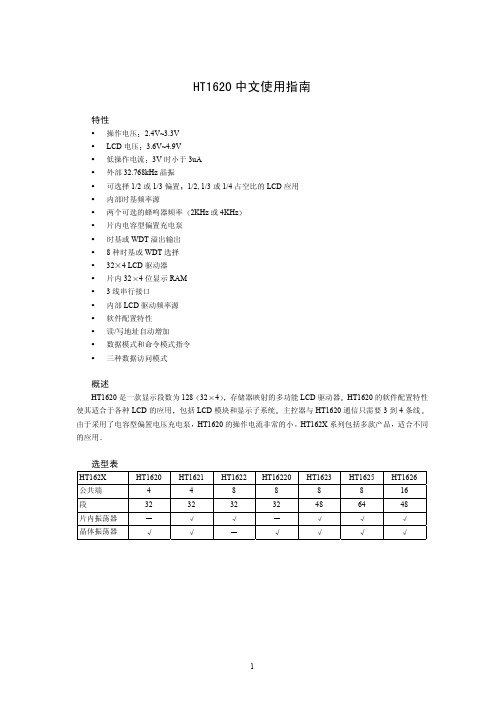
HT1621中文使用说明
信号的下降沿输出 输出的数据出现在 DATA 线上 主控器可
2kHz 或 4kHz 音调频率输出
供倍压电路和半压电路使用
极限参数
电源电压 ......................................... -0.3V~3.6V 输入电压 ......................................... VSS-0.3V~VDD+0.3V 保存温度 ......................................... -50 工作温度 ......................................... -25 ~125 ~75
DC 特性
符号 VDD IDD ISTB VIL VIH IOL1 IOH1 IOL2 IOH2 IOL3 IOH3 RPH * 空载 参数 操作电压 操作电流 待机电流 低电平输入电压 高电平输入电压 DATA,BZ,BZ,IRQ DATA,BZ,BZ LCD 公共端灌电流 LCD 公共端拉电流 LCD 段灌电流 LCD 段拉电流 上拉电阻 3V 3V 3V 3V 3V 3V 3V 3V 3V 3V 3V 空载* 空载* DATA,WR,CS,RD DATA,WR,CS,RD VOL=0.3V VOH=2.7V VOL=0.3V VOH=2.7V VOL=0.3V VOH=2.7V DATA,WR,CS,RD CS=WR=RD=高电平 2.4 0.8 -0.6 80 -70 70 -30 40 1.6 -1.2 150 -120 140 -60 80 150 测试条件 VDD 条件 最小 2.4 2 1 典型值 最大 3.3 3 5 1 3.0 单位 V uA uA V V mA mA uA uA uA uA kΩ
电子电流监测线路CM-SRS.1数据手册说明书
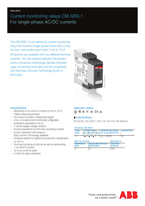
2C D C 251 055 V 0011Current monitoring relays CM-SRS.1For single-phase AC/DC currentsThe CM-SRS.1 is an electronic current monitoring relay that monitors single-phase mains (DC or AC) for over- and undercurrent from 3 mA to 15 A.All devices are available with two different terminal versions. You can choose between the proven screw connection technology (double-chamber cage connecting terminals) and the completely tool-free Easy Connect Technology (push-in terminals).Characteristics–Monitoring of DC and AC currents (3 mA to 15 A) –TRMS measuring principle–One device includes 3 measuring ranges–Over- or undercurrent monitoring configurable –Hysteresis adjustable (3-30 %) – 3 control supply voltage versions–Precise adjustment by front-face operating controls –Screw connection technology orEasy Connect Technology available–Housing material for highest fire protection classificationUL 94 V-0–Tool-free mounting on DIN rail as well as demounting – 1 c/o (SPDT) contact –22.5 mm (0.89 in) width – 3 LEDs for status indicationApprovals / MarksA C R E L /a bClassifcations:EN 50155, IEC 60571, NF F 16-101/102, EN 45545-2EN 50155, IEC 60571Temp. class Voltage supply Vibration and shockacc to IEC/EN 61373Coated pcb.S1S2C1C2T3nnn-Cat 1, Class BnoNF F 16-101/102EN 45545-2Flammability index Opticity and toxicity of smoke index Risk level achieved I2F2HL3Order dataCurrent monitoring relaysType Rated control supply voltage Connection technology Measuring ranges Order code CM-SRS.11P24-240 V AC/DC Push-in terminals3-30 mA, 10-100 mA, 0.1-1 A1SVR740840R0200 110-130 V AC1SVR740841R0200220-240 V AC1SVR740841R1200 CM-SRS.11S24-240 V AC/DC Screw type terminals3-30 mA, 10-100 mA, 0.1-1 A1SVR730840R0200 110-130 V AC1SVR730841R0200220-240 V AC1SVR730841R1200 CM-SRS.12S24-240 V AC/DC Screw type terminals0.3-1.5 A, 1-5 A, 3-15 A1SVR730840R0300 110-130 V AC1SVR730841R0300220-240 V AC1SVR730841R1300AccessoriesType Description Order code ADP.01Adapter for screw mounting1SVR430029R0100 MAR.12Marker label for devices with DIP switches1SVR730006R0000 COV.11Sealable transparent cover1SVR730005R01002 - Current monitoring relays CM-SRS.1 | Data sheetData sheet | Current monitoring relays CM-SRS.1 - 3Connection technologyMaintenance free Easy Connect Technology with push-in terminalsType designation CM-xxS.yyPApproved screw connection technology with double-chamber cage connecting terminals Type designation CM-xxS.yySPush-in terminals–Tool-free connection of rigid and flexible wires withwire end ferrule–Easy connection of flexible wires without wire endferrule by opening the terminals –No retightening necessary–One operation lever for opening both connectingterminals–For triggering the lever and disconnecting of wiresyou can use the same tool (Screwdriver according to DIN ISO 2380-1 Form A 0.8 x 4 mm (0.0315 x 0.157 in), DIN ISO 8764-1 PZ1 ø 4.5 mm (0.177 in))–Constant spring force on terminal point independentof the applied wire type, wire size or ambientconditions (e. g. vibrations or temperature changes) –Opening for testing the electrical contacting –Gas-tightDouble-chamber cage connecting terminals–Terminal spaces for different wire sizes–One screw for opening and closing of both cages –Pozidrive screws for pan- or crosshead screwdriversaccording to DIN ISO 2380-1 Form A 0.8 x 4 mm (0.0315 x 0.157 in), DIN ISO 8764-1 PZ1 ø 4.5 mm (0.177 in)Both the Easy Connect Technology with push-in terminals and screw connection technology with double-chamber cageconnecting terminals have the same connection geometry as well as terminal position.2C D C 253 025 F 00112C D C 253 026 F 00114 - Current monitoring relays CM-SRS.1 | Data sheetFunctions Operating controls2C D C 251 055 V 00111 Adjustment of the hysteresis (MIN = Default)2 Adjustment of the threshold value (MIN = Default)3 Indication of operational states U/T: green LED – control supply voltage R: yellow LED – relay status I: red LED – over- / undercurrent4 DIP switches (see DIP switch functions)ApplicationThe current monitoring relays CM-SRS.1 are designed for use in single-phase AC and/or DC systems for over- orundercurrent monitoring. The devices are available with different supply voltage ranges and work according to the open-circuit principle. Operating modeThe CM-SRS.1 with 1 c/o (SPDT) contact are available in 2 versions with 3 measuring ranges: 3-30 mA, 10-100 mA, 0.1-1 A (CM-SRS.11) and 0.3-1.5 A, 1-5 A, 3-15 A (CM-SRS.12). The measuring range is selected by connecting the monitored wire to the corresponding terminal B1/B2/B3-C.The units are adjusted with front-face operating controls. The selection of over- b or undercurrent monitoring a ismade with a DIP switch. Potentiometers, with direct reading scale, allow the adjustment of the threshold value I and of the hysteresis %. The hysteresis % is adjustable within a range of 3 to 30 % of the threshold value.Function diagramsOvercurrent monitoring bThe current to be monitored (measured value) is applied to terminals B1/B2/B3-C. The control supply voltage applied to terminals A1-A2 is displayed by the glowing green LED.If the measured value exceeds the adjusted threshold value, the output relay energizes and the red LED (overcurrent) andthe yellow LED (relay energized) glow.If the measured value drops below the threshold value minus the adjusted hysteresis, the output relay de-energizes and the red and yellow LEDs turn off.Undercurrent monitoring aThe current to be monitored (measured value) is applied to terminals B1/B2/B3-C. The control supply voltage applied to terminals A1-A2 is displayed by the glowing green LED.If the measured value drops below the adjusted threshold value, the output relay energizes, the red LED flashes W (undercurrent) and the yellow LED (relay energized) glows.If the measured value exceeds the threshold value plus the adjusted hysteresis, the output relay de-energizes and the red and yellow LEDs turn off.Data sheet | Current monitoring relays CM-SRS.1 - 5Electrical connectionDIP switches6 - Current monitoring relays CM-SRS.1 | Data sheetTechnical dataData at T a = 25 °C and rated values, unless otherwise indicatedInput circuitsSupply circuit A1-A2Rated control supply voltage U s110-130 V AC220-240 V AC24-240 V AC/DC Rated control supply voltage U s tolerance-15...+10 %Rated frequency50/60 Hz50/60 Hz or DC Typical current / power consumption24 V DC--30 mA / 0.75 W115 V AC24 mA / 2.6 VA-17 mA / 1.9 VA230 V AC-12 mA / 2.6 VA11 mA / 2.6 VA Power failure buffering time20 msTransient overvoltage protection varistorsMeasuring circuit B1/B2/B3-CMonitoring function over- or undercurrent monitoring configurableMeasuring method TRMS measuring principleMeasuring inputs CM-SRS.11CM-SRS.121)terminal connection B1-C B2-C B3-C B1-C B2-C B3-Cmeasuring range3-30 mA10-100 mA0.1-1 A0.3-1.5 A1-5 A3-15 Ainput resistance 3.3 Ω 1 Ω0.1 Ω0.05 Ω0.01 Ω0.0025 Ωpulse overload capacity t < 1 s500 mA 1 A10 A15 A50 A100 Acontinuous capacity50 mA150 mA 1.5 A 2 A7 A17 A Threshold value adjustable within the indicated measuring range Tolerance of the adjusted threshold value10 % of the range end valueHysteresis related to the threshold value3-30 % adjustableMeasuring signal frequency range DC / 15 Hz - 2 kHzRated measuring signal frequency range DC / 50-60 HzMaximum response time AC80 msDC120 msAccuracy within the rated control supply voltage toleranceΔU ≤ 0.5 %Accuracy within the temperature rangeΔU ≤ 0.06 % / °CTiming circuitTime delay T V noneRepeat accuracy (constant parameters)±0.07 % of full scaleUser interfaceIndication of operational statesControl supply voltage U/T: green LED V: control supply voltage appliedMeasured value I: red LED V: overcurrentW: undercurrentRelay status R: yellow LED V: output relay energized1) For usage of the current monitoring relays according to UL, following limitations for the measuring circuits are applicable: The load on any single measuring circuit should not exceed15 A at 51-150 V, 10 A at 151-300 V or 5 A at 301-600 V.This limitation is only valid for application according to UL and not for IEC applications.Data sheet | Current monitoring relays CM-SRS.1 - 7Output circuitsKind of output1115-1216/1418relay, 1 c/o (SPDT) contactOperating principle open-circuit principle (output relay energizes if themeasured value exceeds b / falls below a theadjusted threshold value)Contact material AgNiRated operational voltage U e250 VMinimum switching voltage / Minimum switching current24 V / 10 mAMaximum switching voltage / Maximum switching current250 V AC / 4 A ACRated operational current I e AC-12 (resistive) at 230 V 4 AAC-15 (inductive) at 230 V 3 ADC-12 (resistive) at 24 V 4 ADC-13 (inductive) at 24 V 2 AAC rating (UL 508)utilization category (Control Circuit Rating Code) B 300max. rated operational voltage300 V ACmax. continuous thermal current at B 300 5 Amax. making/breakingapparent power at B 3003600/360 VAMechanical lifetime30 x 106 switching cyclesElectrical lifetime AC-12, 230 V, 4 A0.1 x 106 switching cyclesMaximum fuse rating to achieve short-circuit protection n/c contact 6 A fast-acting n/o contact 10 A fast-actingGeneral dataMTBF on requestDuty time100 %Dimensions (W x H x D)product dimensions22,5 x 85,6 x 103,7 mm (0,89 x 3,37 x 4,08 in)packaging dimensions97 x 109 x 30 mm (3,82 x 4,29 x 1,18 in)Weight Screw connectiontechnology Easy Connect Technology (Push-in)net weight CM-SRS.11Version 24-240 V AC/DC0.145 kg (0.320 lb)0.137 kg (0.302 lb)Version 110-130 V AC 0.161 kg (0.355 lb)0.153 kg (0.337 lb)Version 220-240 V AC0.161 kg (0.355 lb)0.153 kg (0.337 lb)CM-SRS.12Version 24-240 V AC/DC0.137 kg (0.302 lb)-Version 110-130 V AC 0.168 kg (0.370 lb)-Version 220-240 V AC0.168 kg (0.370 lb)-gross weight CM-SRS.11Version 24-240 V AC/DC0.147 kg (0.324 lb)0.159 kg (0.351 lb)Version 110-130 V AC 0.183 kg (0.403 lb)0.175 kg (0.386 lb)Version 220-240 V AC0.183 kg (0.403 lb)0.175 kg (0.386 lb)CM-SRS.12Version 24-240 V AC/DC0.159 kg (0.351 lb)-Version 110-130 V AC 0.200 kg (0.441 lb)-Version 220-240 V AC0.200 kg (0.441 lb)-Mounting DIN rail (IEC/EN 60715),snap-on mounting without any tool Mounting position anyMinimum distance to other units10 mm (0.39 in) at measured current > 10 A Material of housing UL 94 V-0Degree of protection housing IP50terminals IP208 - Current monitoring relays CM-SRS.1 | Data sheetElectrical connectionEnvironmental dataAmbient temperature ranges operation-25...+60 °C (-13...+140 °F)storage-40...+85 °C (-40...+185 °F)Damp heat, cyclic (IEC/EN 60068-2-30)55 °C, 6 cyclesVibration, sinusoidal Class 2Shock Class 2Isolation dataRated insulation voltage U i supply / measuring circuit / output 600 Voutput 1 / output 2250 VRated impulse withstand voltage U imp supply / measuring circuit / output 6 kV 1.2/50 μsoutput 1 / output 2 4 kV 1.2/50 μsPollution degree3Overvoltage category IIIStandards / DirectivesStandards IEC/EN 60947-5-1, IEC/EN 60255-27, EN 50178 Low Voltage Directive2014/35/EUEMC Directive2014/30/EURoHS Directive2011/65/EURailway application standardsEN 50155, IEC 60571“Railway applications – Electronic equipment used on rolling stock”temperature class T3 supply voltage category S1, S2, C1IEC/EN 61373“Railway applications – Rolling stock equipment – Shock and vibration tests”Category 1, Class BEN 45545-2 Railway applications – Fire protection on railway vehicles – part 2:Requirements for fire behavior of materialsHL3and components ISO 4589-2LOI 32.3 %NF X-70-100-1 C.I.T. (T12) 0.45EN ISO 5659-2Ds max (T10.03) 104NF F 16-101: Rolling stock. Fire behaviour. Materials choosingNF F 16-102: Railway rolling stock. Fire behaviour. Materials choosing, application forelectric equipmentI2 / F2DIN 5510-2 Preventive fire protection in railway vehicles. Part 2: Fire behaviour and fireside effects of materials and partsfullfilledData sheet | Current monitoring relays CM-SRS.1 - 9Electromagnetic compatibilityInterference immunity to IEC/EN 61000-6-2 electrostatic discharge IEC/EN 61000-4-2Level 3radiated, radio-frequency, electromagnetic field IEC/EN 61000-4-3Level 3electrical fast transient / burst IEC/EN 61000-4-4Level 3surge IEC/EN 61000-4-5Level 3conducted disturbances, induced byIEC/EN 61000-4-6Level 3 radio-frequency fieldsInterference emission IEC/EN 61000-6-3 high-frequency radiated IEC/CISPR 22, EN 55022Class Bhigh-frequency conducted IEC/CISPR 22, EN 55022Class BTechnical diagramsLoad limit curvesDC load (resistive)AC load (resistive)Derating factor F for inductive AC loadContact lifetime10 - Current monitoring relays CM-SRS.1 | Data sheetDimensionsin mm and inchesAccessoriesin mm and inchesCOV.11 - Sealable transparent coverADP.01 - Adapter for screw mounting MAR.12 - Marker label for deviceswith DIP switchesFurther documentationDocument title Document type Document numberElectronic products and relays Technical catalogue2CDC 110 004 C02xxCM-SRS.1, CM-SRS.2Instruction manual1SVC 730 610 M0000You can find the documentation on the internet at /lowvoltage-> Automation, control and protection -> Electronic relays and controls -> Measuring and monitoring relays.CAD system filesYou can find the CAD files for CAD systems at -> Low Voltage Products & Systems -> Control Products -> Electronic Relays and Controls.Data sheet | Current monitoring relays CM-SRS.1 - 11ABB STOTZ-KONTAKT GmbHP. O. Box 10 16 8069006 Heidelberg, Germany Phone: +49 (0) 6221 7 01-0Fax: +49 (0) 6221 7 01-13 25E-mail:*****************.comYou can find the address of your local sales organisation on theABB home page/contacts-> Low Voltage Products and Systems Contact usNote:We reserve the right to make technical changes or modify the contents of this document without prior notice. With regard to purchase orders, the agreed particulars shall prevail. ABB AG does not accept any responsibility whatsoever for potential errors or possible lack of information in this document.We reserve all rights in this document and in the subject matter and illustrations contained therein. Any reproduction, disclosure to third parties or utilization of its contents – in wholeor in parts – is forbidden without prior written consent of ABB AG.Copyright© 2019 ABBAll rights reserved D o c u m e n t n u m b e r 2 C D C 1 1 2 1 6 7 D 0 2 0 1 R e v D ( 0 3 / 2 0 1 9 )。
- 1、下载文档前请自行甄别文档内容的完整性,平台不提供额外的编辑、内容补充、找答案等附加服务。
- 2、"仅部分预览"的文档,不可在线预览部分如存在完整性等问题,可反馈申请退款(可完整预览的文档不适用该条件!)。
- 3、如文档侵犯您的权益,请联系客服反馈,我们会尽快为您处理(人工客服工作时间:9:00-18:30)。
Dimensions in inches and (millimeters)
Version: C07
SRS1620 - SRS16150
16.0 AMPS. Surface Mount Schottky Barrier Rectifiers
D 2
PAK
Features
For surface mounted application Low forward voltage drop High current capability High reliability
High surge current capability
Mechanical Data
Cases: D 2
PAK molded plastic
Epoxy: UL 94V-0 rate flame retardant Terminals: Pure tin plated, lead free.
solderable per MIL-STD-202, Method 208 guaranteed
Polarity: As marked
High temperature soldering guaranteed:
260o
C/10 seconds at terminals Weight: 1.70 grams
Maximum Ratings and Electrical Characteristics
Rating at 25 o C ambient temperature unless otherwise specified. Single phase, half wave, 60 Hz, resistive or inductive load. For capacitive load, derate current by 20%
Type Number
Symbol SRS 1620 SRS 1630
SRS 1640 SRS 1650 SRS
1660 SRS 1690 SRS 16100 SRS 16150
Units Maximum Recurrent Peak Reverse Voltage V RRM
20 304050 60 90 100150V Maximum RMS Voltage V RMS 14 212835 42 63 70 105V Maximum DC Blocking Voltage V DC 20 304050 60 90 10 150
V Maximum Average Forward Rectified
Current See Fig. 1
I (AV) 16 A Peak Forward Surge Current, 8.3 ms Single Half Sine-wave Superimposed on Rated Load (JEDEC method )
I FSM 150
A
Maximum Instantaneous Forward Voltage
@8.0A
V F 0.55 0.70 0.90 1.00 V 0.5 0.1 Maximum D.C. Reverse Current @ Tc=25 o
C at Rated DC Blocking Voltage @ Tc=100 o
C
I R 15 10 5.0
mA
mA Typical Junction Capacitance (Note 2) Cj
700 460 320 pF
Typical Thermal Resistance (Note 1) R θJC 2.0
o
C/W Operating Junction Temperature Range
T J -65 to +125
-65 to +150
o C Storage Temperature Range T STG
-65 to +150 o C
Notes: 1. Thermal Resistance from Junction to Case Per Leg
2. Measured at 1MHz and Applied Reverse Voltage of 4.0V D.C.
RATINGS AND CHARACTERISTIC CURVES (SRS1620 THRU SRS16150)
FIG.2- MAXIMUM NON-REPETITIVE FORWARD SURGE CURRENT PER LEG
P E A K F O R W A R D S U R G E C U R R E N T . (A )
12
51020100
50 0
50200
150
100
250
300
NUMBER OF CYCLES AT 60Hz
FIG.1- MAXIMUM FORWARD CURRENT DERATI NG CURVE
A V E R A G E F O R W A R D C U R R E N T . (A )
o
CASE TEMPERATURE. (C)
Version: C07
FIG.4- TYPICAL REVERSE CHARACTERISTICS
I N S T A N T A N E O U S R E V E R S E C U R R E N T . (m A )
204060801001201401.0
10
PERCENT OF RATED PEAK REVERSE VOLT AGE. (%)
FIG.6- TYPICAL TRANSIENT THERMAL CHARACTERISTICS
O T R A N S I E N T T H E R M A L I M P E D A N C E . (C /W )
1
0.010.1
10100
0.1
10
1
100
PULSE DURATION. (sec)
FIG.5- TYPICAL JUNCTION CAPACIT ANCE PER LEG
C A P A C I T A N C E .(p F )
200
400
800REVERSE VOLTAGE. (V)
FIG.3- TYPICAL FORWARD CHARACTERISTICS I N S T A N T A N E O U S F O R W A R D C U R R E N T . (A )
INSTANTANEOUS FORW ARD VOLTAGE. (V)。