ASC-ME24使用说明书
OSS24智能自适应人流传感器壁开关说明书
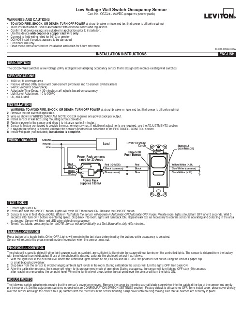
WARNINGS AND CAUTIONS• TO AVOID FIRE, SHOCK, OR DEATH: TURN OFF POWER at circuit breaker or fuse and test that power is off before wiring!• To be installed and/or used in accordance with electrical codes and regulations.• Confirm that device ratings are suitable for application prior to installation.• Use this device with copper or copper clad wire only .• Connect to field wiring rated for 60° C or greater.• DO NOT install if product appears to be damaged.• For indoor use only.•Read these instructions before installation and retain for future reference.The OSS24 Wall Switch is a low voltage (24V) intelligent self-adapting occupancy sensor that is designed to replace existing wall switches.DESCRIPTION• 1000 sq. ft. coverage area• Passive Infrared (PIR) sensor with dual-element pyrometer and 12-element cylindrical lens • 24VDC (requires power pack)• Adjustable Time Delay: 4-30 minutes; self-adjusts based on occupancy • Light Level Adjustment: 10 to 500FC •UL, cUL ListedSPECIFICATIONSINSTALLATION1.WARNING: TO AVOID FIRE, SHOCK, OR DEATH: TURN OFF POWER at circuit breaker or fuse and test that power is off before wiring!2.Remove the old switch if applicable.3.Wire as shown in WIRING DIAGRAM. NOTE: OSS24 requires one power pack per output.4.Install sensor in wall box using mounting screws provided.5.Restore power to the sensor and allow it to initialize (up to 2 minutes).6.Sensor is factory configured to provide the most energy savings. If additional adjustments are required, see the ADJUSTMENTS section.7.If daylight harvesting is desired, calibrate the sensor’s photocell as described in the PHOTOCELL CONTROL section.8.Install wall plate (not included). Installation is complete .TEST MODE1.Ensure lights are ON.2.Press and hold the ON/OFF button. Lights will cycle OFF then back ON. Release the ON/OFF button.3.Sensor is now in Test Mode (NOTE: While in Test Mode the sensor will operate in Automatic ON/Automatic OFF mode). Vacate room; lights should turn OFF after 5 seconds. Wait 5 seconds after turn OFF before re-entering space. Step back into room, lights will turn back ON. Repeat walk test as necessary to confirm sensor is operating and detecting in the area as desired. Sensor will flash red LED when detecting occupancy.4.To exit Test Mode, press any button (NOTE: Sensor will automatically exit Test Mode after sixty (60) minutes).MANUAL OVERRIDEPress button(s) to toggle lights ON or OFF. Lights will remain in the last state determined by the buttons while occupancy is detected.Sensor will return to the programmed mode of operation when the sensor times out.ADJUSTMENTSThe following switch adjustments require that the sensor’s cover be removed. Remove the cover by inserting a small blade screwdriver into the catch at the top of the sensor and gently pry the cover off. Set the adjustment switches as desired (see CONFIGURATION SWITCH SETTINGS section). Factory default is all switches OFF. To re-install cover, place cover directly over the sensor and align the cover’s four (4) catches with the recesses in the sensor housing. Snap cover onto housing making sure that all catches are securely in place.PHOTOCELL CONTROLThe photocell is used to detect if other light sources such as sunlight, are sufficient to illuminate the space without turning on the controlled lights. The sensor is shipped from the factory with the photocell control disabled. If use of the photocell is desired, calibrate the photocell set point as follows:1.With the light level at the desired level where the controlled lights should be off, PRESS and RELEASE the photocell set button using the end of a paper clip or small bladed screwdriver.2.Step back from the sensor to avoid changing ambient light levels in the room. During calibration the sensor will turn the lights OFF then back ON.3.After the calibration process, the sensor will return to its programmed mode of operation. During occupancy, the sensor will turn lighting OFF sixty (60) seconds after reaching or exceeding the set point level. When the lighting level drops below the set point level the sensor will turn the lights ON.DI-000-OSS24-05ALow Voltage Wall Switch Occupancy SensorCat. No. OSS24 - 24VDC (requires power pack)WIRING DIAGRAMGround Neutral LineDI-000-OSS24-05A© 2016 Leviton Mfg. Co., Inc.Switch 1 - Relay 1 Sensor OperationPrograms the sensor for either Manual ON/Automatic OFF operation or Automatic ON/Automatic OFF operation. When set to Manual ON/Automatic OFF mode, lights are turned ON by manually pressing the ON/OFF button. If the sensor times out and turns the lights OFF in the Manual ON/Automatic OFF mode while the space is still occupied, any motion detected within thirty (30) seconds will automatically turn the lights back ON, without requiring the user to press the ON button.Switch 2 - NOTE: Switch 2 has no function on single relay models.Switch 3 - Adaptive or Fixed TimerControls selection between Adaptive Timer Mode and Fixed Timer Mode. In Adaptive Timer Mode, the sensor automatically self-adjusts its timeout delay to optimize energy savings. The sensor will initialize its timer value to eight (8) minutes. If the Bank B Timer Select 0 and Timer Select 1 switches have been set to four (4) minutes, this will be the smallest timer value used. In Fixed Timer Mode, the sensor’s self-adapting timer functions are disabled and the sensor’s timeout delay is set according to the Bank B Timer Select 0 and Timer Select 1 switch settings.Switch 4 - Adaptive ResetThe sensor is equipped with self-adaptive technology which automatically adjusts the sensor’s sensitivity and timer settings to optimize performance based on occupancy patterns. The sensor constantly learns and adjusts appropriately. If the learned settings need to be reset (e.g. when relocating sensor to another area), toggle the switch ON then OFF. The adaptive timer is reset according to the Bank B Timer Select 0 and Timer Select 1 switches. The adaptive sensitivity is reset to factory default. The photocell sensor settings are also reset to factory default (disabled) such that the sensor will turn on the light(s) in response to occupancy regardless of ambient light levels in the lighted space. (NOTE: Adaptive reset can also be achieved by pressing and holding the photocell set button for ten (10) seconds).Switch 5 – Relay BypassIf it is necessary to service the controlled circuits without de-energizing them at the breaker panel (NOTE: this is not recommended as a standard procedure), perform the following steps:1. With the lights ON, set the relay bypass switch to the ON position.2. Push the button(s) to turn the lights OFF.3. Push the button(s) again to verify override (lights should not come back on).The relay bypass switch will now interrupt sensor operation, preventing output(s) from turning ON again, regardless of occupancy or pushbutton conditions. To return the sensor to normal operation, flip the relay bypass switch to the OFF position. To confirm sensor is operating normally, lights should now turn ON and OFF when the button(s) are pressed.Switches 1 and 2 – Timer SettingsSets the length of time lights will remain ON after last motion is detected. The timeout value can be set to 4, 8, 16 or 30 minutes.See Bank A – Switch 3 - Adaptive or Fixed Timer section for additional information.Switches 3 and 4 - Sensing Technology Enable/DisableEnables or disables the occupancy sensing technologies used by the sensor. If all sensing technologies are disabled, sensor operates as a manual ON/OFF switch.Switch 5 - SensitivitySets the sensor’s initial Passive Infrared (PIR) sensitivity level. Sensitivity can be set to either High or Low.For Technical Assistance Call: 1-800-824-3005 (U.S.A. Only) LIMITED 5 YEAR WARRANTY AND EXCLUSIONSLeviton warrants to the original consumer purchaser and not for the benefit of anyone else that this product at the time of its sale by Leviton is free of defects in materials and workmanship under normal and proper use for five years from the purchase date. Leviton’s only obligation is to correct such defects by repair or replacement, at its option. For details visit or call 1-800-824-3005. This warranty excludes and there is disclaimed liability for labor for removal of this product or reinstallation. This warranty is void if this product is installed improperly or in an improper environment, overloaded, misused, opened, abused, or altered in any manner, or is not used under normal operating conditions or not in accordance with any labels or instructions. There are no other or implied warranties of any kind, including merchantability and fitness for a particular purpose , but if any implied warranty is required by the applicable jurisdiction, the duration of any such implied warranty, including merchantability and fitness for a particular purpose, is limited to five years. Leviton is not liable for incidental, indirect, special, or consequential damages, including without limitation, damage to, or loss of use of, any equipment, lost sales or profits or delay or failure to perform this warranty obligation . The remedies provided herein are the exclusive remedies under this warranty, whether based on contract, tort or otherwise.FOR CANADA ONLYFor warranty information and/or product returns, residents of Canada should contact Leviton in writing at Leviton Manufacturing of Canada Ltd to the attention of the Quality Assurance Department, 165 Hymus Blvd, Pointe-Claire (Quebec), Canada H9R 1E9 or by telephone at 1 800 405-5320.* Only functional on multi-tech models.。
MELAG 24B中文说明-06.6

高温消毒柜
Vacuklav® 24-B
德国 Melag oHG 公司生产 Geneststra Be 9-10 d-10829 Berlin 售后服务机构:上海天鹰医疗器械有限公司
亲爱的医生用户: 非常感谢你们对我们产品的信任,购买这款高温消毒柜产品。 至今有 50 多年的历史,MELAG—一个中等规模,家族企业—专业从事医疗应用消毒设备的产品 经营。在此期间,MELAG 已经成功地成为了消毒设备行业的领头人。 超过 335,000 台 MELAG 机器销往世界各地,证明了我们的消毒系统的卓越的质量—只在德国生产。 和其他 MELAG 产品一样,这款消毒柜经过严格的质量标准测试。在操作机器之前,请仔细阅读 安装和造作手册。消毒柜的长期功能有效性取决于消毒前的准备工作及合理的保养。 MELAG 全体员工
4 消毒程序的所有指令 .................................................................................................................................... 11 4.1 电力供应和水供应................................................................................................................................. 11 4.1.1 蒸馏水和脱矿水的供应 .................................................................................................................. 11 4.1.2 电源供应........................................................................................................................................ 11 4.2 消毒柜的放置........................................................................................................................................ 11 4.3 关闭门................................................................................................................................................... 12 4.4 程序选择 ............................................................................................................................................... 12 4.5 启动程序 ............................................................................................................................................... 13 4.6 程序进展 ............................................................................................................................................... 13 4.7 打印记录 ............................................................................................................................................... 15 4.8 移开消毒物 ........................................................................................................................................... 15 4.9 无菌贮藏室 ........................................................................................................................................... 15 4.10 频繁消毒/终止 ...................................................................................................................................... 16 4.11 手动终止程 ........................................................................................................................................... 16 4.11.1 终止灭菌........................................................................................................................................ 16 4.11.2 终止干燥........................................................................................................................................ 17 4.12 对警告/错误信息反应 ........................................................................................................................... 18 4.13 暂停操作 ............................................................................................................................................... 18
MultiSync EA242F 24英寸显示器数据手册说明书

DatasheetPowering workspace communicationsPowering your PC/notebook and all your devices through a single cable, the MultiSync®EA242F is your workspace hub; no docking station required, the 65W USB-C connection means an efficient, clutter-free workstation from which to manage your communications. Easily increase your display area using DisplayPort-out to daisy-chain multiple displays, no additional cabling required.User comfort is fundamental with full height adjustment, tilt, pivot and swivel supporting customised personal setup, whilst built-in low blue light technologies guard against eye fatigue without compromising true-to-life colour performance. Available in black or white, the 24” EA242F complements office interior design and ergonomics.The connectivity advantage continues beyond USB T ype-C with DisplayPort, HDMI, VGA and USB A for fully future-proof flexibility supporting new open office standards in hot desking and ‘bring your own device.’BenefitsIn-demand display size– the popular 23.8” display with Full HD resolution is the perfect size for busy office workspaces. Future-proof flexibility– wide connectivity provides high-level flexibility with DP, HDMI, USB T ype C, USB A and audio output. Clutter-free workspace– Powerful 65W USB T ype-C connectivity manages video, audio, power and USB via a single cableEasy multi-screen set-up– Daisy-chain multiple display configurations through DisplayPort-out, no additional cables neededMaximum attention to health and well-being– the outstanding ergonomic height adjustment from 0 to 150 mm; eye pleasing built-in Low Blue Light and Flicker-Free technology; plus integrated ambient light sensor all combines to tailor the perfect individual setup to boost productivity.Product InformationProduct Name NEC MultiSync®EA242FProduct Group LCD 23.8" Enterprise DisplayOrder Code60005246 (WH), 60005032 (BK)DisplayPanel T echnology IPS TFT with W-LED backlightScreen Size [inch/cm]24 / 60.47Screen Aspect Ratio16:9Colour Gamuts101.6 % sRGB; 75.3% AdobeRGB, 72% NTSCPixel Pitch [mm]0.275Brightness (typ.) [cd/m²]250Contrast Ratio (typ.)1000:1 (5000:1 dynamic contrast ratio)Viewing Angle [°]178 horizontal / 178 vertical (typ. at contrast ratio 10:1) Response Time (typ.) [ms] 5 (grey-to-grey)Colours [Mio.]16.78 (6-bit per colour)Synchronisation RateHorizontal Frequency [kHz]31.5 - 83Vertical Frequency [Hz]50 - 75ResolutionOptimum Resolution1920 x 1080 at 60 HzSupported1024 x 768;1280 x 1024;1280 x 720;1280 x 960;1440 x 900;1680 x 1050;1920 x 1080;640 x 480;720 x 400;720 x 480;720 x 576;800 x 600ConnectivityDigital 1 x DisplayPort; 1 x DisplayPort out; 1 x HDMI; 1 x USB T ype C; USB ver. 3.1 (3 down / 1 up) Analog 1 x D-sub 15 pinElectricalPower Consumption on Mode[W]15 (Eco Mode 2); 21 (typ.)Power Savings Mode [W]0.3Power Supply0.9 A/0.5 A; 100-240 V; internal power supplyEnvironmental ConditionsOperating T emperature [°C]+5 to +35Operating Humidity [%]20 to 80Storage Humidity [%]10 to 85Storage T emperature [°C]-10 to 60ErgonomicsHeight adjustable stand [mm]150 (Landscape mode)Screen Tilt [°]-5 to 35Screen Swivel [°]-170 to 170Screen Rotate [°]0 to 90 (landscape to portrait mode)MechanicalBezel Width [mm]0.8 (left/right/top); 15.8 (bottom)Dimensions (W x H x D) [mm]319.1 x 555.6 - 615.4 x 250 (Portrait mode); 537.7 x 336.6 - 486.6 x 250 (Landscape mode) Weight [kg]With stand: 7VESA Mounting [mm]100 x 100 (4 points)Additional FeaturesColour Versions Black Front Bezel, Black Back CabinetCable Management yesKensington security slot yesPlug and Play DDC2B/2Bi; VESA DDC/CI; VESA DDC2BiAudio Integrated Speakers (1 W + 1 W)Adjust Functions Advanced NTAA (Advanced Non-T ouch-Auto-Adjustment)Shipping Content Control Sync Cable; DisplayPort cable; Monitor; Power Cable; Set-up Manual; USB Cable; USB-C CableSafety and Ergonomics CE; EAC; EnergyStar 8.0; ErP; Flicker-free; ISO 9241-307 (pixel failure class I); Low Blue Light;PSB; RoHS; TCO 8.0; TÜV Ergonomics; TÜV GS; UL/C-UL or CSA; WEEEWarranty 3 years warranty incl. backlight; optional 1st to 3rd year 24/7 usage warranty; optional 4th to5th year warranty extensionGreen FeaturesEnergy Efficiency Ambient light sensor; Energy consumption: 13 kWh/1000 h; Energy efficiency class: D;Human sensorEcological Standards ErP compliant; RoHS compliant; WEEETÜVErgonomics TÜV GS TCO 8.0RoHS ErP CEThis document is © 2022 Sharp NEC Display Solutions Europe GmbH.All rights reserved in favour of their respective owners. All hardware and software names are brand names and/or registered trademarks of the respective manufacturers. All specifications are subject to change without notice. Errors and omissions are excepted. 03.02.2022。
法国真空计-ACS控制器

设置点使用,耦合装置的隔离和继电器变得无效,因此建议使用外接电源。
七 技术参数
主要规格 环境 适用真空计
电压 频率 功耗 重量 超电压类别 防护等级 存储温度 运行温度 相对湿度 使用 污染程度 防护等级 真空计数量 真空计类型
100 - 240VAC
50∕60Hz
<50VA
1.3kg 类别Ⅱ Note1 等级Ⅰ装置 Note2 -20~+60℃ Note3 +5~+50℃ <70% 仅用于室内 最高海拔 2000m 污染程度Ⅱ Note4 IP30 Note5
作为一个 EMC 测量,外部连接使用带屏蔽的电线。屏蔽必须 在另一端设备处接地。忽视可导致干扰造成的错误或设备损 坏。 当使用继电器输出接点时,接点容量必须在 125VAC,0.3A 或 小于 30VDC,1A。忽视可导致干扰造成的错误或设备损坏。
24VDC 电源仅用于远程控制或继电器输出时的压力信号输 出,与高阻抗设备连接并使用小电流。始终使用 0.1A 以下电 源。忽视可导致设备损坏。
备注:必须进行正确的接地,否则容易造成电击
4 打开电源开关.
四 控制器显示
1 控制器自我测试
2 显示控制器版本
3 显示真空计型号
如果连接 AP2004 会显示”AP”(图示 AHC 为另一型号真空计) 4 显示真空计所测之处的真空度(如果真空计连接正确)
SM24A 调节器说明书

SM24ADamper actuator for adjusting dampers intechnical building installations• Air damper size up to approx. 4 m²• Torque motor 20 Nm• Nominal voltage AC/DC 24 V• Control Open/close, 3-pointTechnical dataElectrical data Nominal voltage AC/DC 24 VNominal voltage frequency50/60 HzNominal voltage range AC 19.2...28.8 V / DC 19.2...28.8 VPower consumption in operation 2 WPower consumption in rest position0.2 WPower consumption for wire sizing 4 VAConnection supply / control Cable 1 m, 3x 0.75 mm²Parallel operation Yes (note the performance data)Functional data Torque motor20 NmDirection of motion motor selectable with switch 0 (ccw rotation) / 1 (cwrotation)Manual override with push-button, can be lockedAngle of rotation Max. 95°Angle of rotation note can be limited on both sides with adjustablemechanical end stopsRunning time motor150 s / 90°Sound power level, motor45 dB(A)Mechanical interface Universal shaft clamp reversible 10...20 mmPosition indication Mechanical, pluggableSafety data Protection class IEC/EN III, Safety Extra-Low Voltage (SELV)Power source UL Class 2 SupplyDegree of protection IEC/EN IP54Degree of protection NEMA/UL NEMA 2Enclosure UL Enclosure Type 2EMC CE according to 2014/30/EUCertification IEC/EN IEC/EN 60730-1 and IEC/EN 60730-2-14UL Approval cULus according to UL60730-1A, UL60730-2-14and CAN/CSA E60730-1The UL marking on the actuator depends onthe production site, the device is UL-compliantin any caseHygiene test According to VDI 6022 Part 1 / SWKI VA104-01, cleanable and disinfectable, lowemissionType of action Type 1Rated impulse voltage supply / control0.8 kVPollution degree3Safety dataAmbient humidity Max. 95% RH, non-condensing Ambient temperature -30...50°C [-22...122°F]Storage temperature -40...80°C [-40...176°F]Servicingmaintenance-free WeightWeight 0.94 kg•••••••Safety notesThis device has been designed for use in stationary heating, ventilation and air-conditioning systems and must not be used outside the specified field of application, especially in aircraft or in any other airborne means of transport.Outdoor application: only possible in case that no (sea) water, snow, ice, insolation or aggressive gases interfere directly with the device and that it is ensured that the ambient conditions remain within the thresholds according to the data sheet at any time.Only authorised specialists may carry out installation. All applicable legal or institutional installation regulations must be complied with during installation.The device may only be opened at the manufacturer's site. It does not contain any parts that can be replaced or repaired by the user.Cables must not be removed from the device.To calculate the torque required, the specifications supplied by the damper manufacturers concerning the cross-section and the design, as well as the installation situation and the ventilation conditions must be observed.The device contains electrical and electronic components and must not be disposed of as household refuse. All locally valid regulations and requirements must be observed.Product featuresSimple direct mountingSimple direct mounting on the damper shaft with a universal shaft clamp, supplied with an anti-rotation device to prevent the actuator from rotating.Manual overrideManual override with push-button possible (the gear train is disengaged for as long as the button is pressed or remains locked).Adjustable angle of rotation Adjustable angle of rotation with mechanical end stops.High functional reliabilityThe actuator is overload protected, requires no limit switches and automatically stops when the end stop is reached.AccessoriesElectrical accessoriesDescriptionType Auxiliary switch 1x SPDT add-on S1A Auxiliary switch 2x SPDT add-onS2A Feedback potentiometer 140 Ω add-on P140A Feedback potentiometer 1 kΩ add-on P1000A Feedback potentiometer 10 kΩ add-onP10000A Mechanical accessoriesDescriptionType Actuator arm for standard shaft clamp (reversible)AH-20Shaft extension 240 mm ø20 mm for damper shaft ø12...21 mm CrNi AV12-25-I Shaft extension 240 mm ø20 mm for damper shaft ø8...22.7 mm AV8-25Ball joint suitable for damper crank arm KH8KG8Ball joint suitable for damper crank arm KH8 / KH10KG10A Damper crank arm Slot width 8.2 mm, clamping range ø10...18 mm KH8Shaft clamp one-sided, clamping range ø8...26 mm, Multipack 20 pcs.K-ENSA Shaft clamp one-sided, clamping range ø12...26 mm, for CrNi shaft (INOX), Multipack 20 pcs.K-ENSA-IDescription Type Shaft clamp reversible, clamping range ø10...20 mm K-SAAnti-rotation mechanism 180 mm, Multipack 20 pcs.Z-ARS180Anti-rotation mechanism 230 mm, Multipack 20 pcs.Z-ARS230 Form fit insert 10x10 mm, Multipack 20 pcs.ZF10-NSAForm fit insert 12x12 mm, Multipack 20 pcs.ZF12-NSAForm fit insert 15x15 mm, Multipack 20 pcs.ZF15-NSA Form fit insert 16x16 mm, Multipack 20 pcs.ZF16-NSA Mounting kit for linkage operation for flat installation ZG-SMA Position indicator, Multipack 20 pcs.Z-PI Baseplate extension for SM..A to SM../AM../SMD24R Z-SMAWire colours:1 = black2 = red3 = whiteElectrical installationSupply from isolating transformer.Parallel connection of other actuators possible. Observe the performance data.Wiring diagramsAC/DC 24 V, open/closeAC/DC 24 V, 3-point DimensionsSpindle lengthMin. 48Min. 20Clamping rangeWhen using a round shaft made of CrNi(INOX): ø12...20 mm。
EM24 Ethernet 能量计手册说明书
DEUTSCHHandbuch zum EnergiezählerEM24 Ethernetrev 05 - 08/2023Diese Handbuch ist auch im HTML5-Format verfügbar.Inhaltsverzeichnis1. Einführung (1)1.1. Merkmale (1)2. Installation und Konfiguration (2)2.1. AC-Verkabelung (2)2.1.1. Konfigurationsoptionen (2)2.1.2. Systembeispiele (2)2.2. GX-Gerätekonfiguration (4)3. Häufig gestellte Fragen (7)Der Victron EM24 Ethernet ist ein Standardgerät zur Messung der Leistung und Energie einer Drei Phasen-Anwendung, z. B. am Verteilerkasten oder zur Messung der Leistung eines PV-Wechselrichters, eines Wechselstromaggregats oder der Leistung eines Wechselrichters und Wechselrichter/Ladegeräts.Seine Daten werden auf einem GX-Gerät und unserem VRM-Portal angezeigt.1.1. MerkmaleDer EM24 Ethernet kann für vier verschiedene Funktionen in einem GX-Gerät wie dem Cerbo GX konfiguriert werden:1.Verwendbar als Netzzähler und als Steuereingang für ein ESS-System.2.Zur Messung der Leistung eines PV-Wechselrichters.3.Zur Messung der Leistung eines Wechselstromaggregats.4.Als Wechselstrommessgerät, um den Wechselstromausgang eines Wechselrichters oder Wechselrichter/Ladegeräts zumessen.Er bietet Eine Option für den Anschluss an ein GX-Gerät:1.Eine Ethernet-Kabelverbindung zum lokalen Netzwerk, die so beschaffen ist, dass das GX-Gerät sie erreichen kann.2.1. AC-Verkabelung2.1.1. KonfigurationsoptionenDie Konfigurationsoption Netzzähler, PV-Wechselrichter, Generator oder Wechselstromzähler wird im GX-Gerät eingestellt.Einzelheiten zur Konfiguration von GX-Geräten finden Sie im Kapitel GX-Gerätekonfiguration [4]. Diese Auswahl betrifft dieVerkabelung des Systems und die Art und Weise, wie die vom Zähler empfangenen Informationen auf dem Bildschirm angezeigt werden.Siehe folgende Diagramme für die verschiedenen Verkabelungsoptionen:2.1.2. SystembeispieleBeispieldiagrammeL1L2L3NPEL1L2L3NPEEM24 3-Phasen-VerkabelungBei der Messung eines PV-Wechselrichters sollten die Anschlüsse 1, 4 und 7 dem PV-Wechselrichterzugewandt sein, um die richtige Strom- und Leistungsrichtung zu gewährleisten.Einphasig mit einer FunktionL1NL1NEM24 angeschlossen als einphasiger Netzzähler mit einer FunktionBeachten Sie den Brückenstecker zwischen den Anschlüssen 1 und 4. Sie benötigen diese Verbindung nicht, wenn Sie die Version AV2 des Sensors besitzen.Die Diagramme zeigen die Verkabelung bei Verwendung als Netzzähler.Um einen einphasigen PV-Wechselrichter in einem 3-Phasen-System zu messen, schließen Sie alle 3 Phasen an die Anschlüsse für die Netzphasen (3, 6 und 9) an. Jetzt können Sie wählen, auf welcher Phase Sie den PV-Wechselrichter haben möchten,indem Sie die L1-Leitung des PV-Wechselrichters an Anschluss 1, 4 oder 7 anschließen.Einphasig mit DoppelfunktionWenn Sie einen dreiphasigen Zähler in einer einphasigen Installation verwenden möchten, um das Netz an einem Eingang des Zählers und den Ausgang des PV-Wechselrichters an einem anderen Eingang des Energiezählers zu messen, sollten Sie sicherstellen, dass der Energiezähler L1 und der PV-Wechselrichter L2 verwendet.Vorderer WahlschalterStellen Sie den vorderen Wahlschalter so um, dass er nicht gesperrt ist. Dadurch kann das Gerät automatisch vom GX-Gerät konfiguriert werden. Der vordere Wahlschalter befindet sich neben dem Display, wie in der Abbildung oben gezeigt.2.2. GX-GerätekonfigurationNach dem ordnungsgemäßen Anschluss und dem Einschalten werden die Zähler auf dem GX-Gerät im Menü Einstellungen →Energiezähler angezeigt:Einzelner Energiezähler im Menü der Energiezähler Zwei Energiezähler im Menü der EnergiezählerNach der Auswahl eines Energiezählers müssen Sie die Funktion und den Phasentyp festlegen. Betätigen Sie die Leertaste oder klicken Sie mit der rechten Maustaste, um das Menü Phasentyp und Funktion aufzurufen:Beim ET112 wird nur die Option Einphasig angezeigt.Je nach Anwendung wird die Funktion hier festgelegtWählen Sie entweder den Funktions- oder den Phasentyp und betätigen Sie die Leertaste, um Änderungen vorzunehmen:Wählen Sie die Funktion entsprechend der Anwendung Auswahlmenü für Einphasen- und Mehrphasentyp Einphasig mit einer Funktion und einphasig mit Doppelfunktion einrichten:Einphasig mit einer Funktion Einphasig mit Doppelfunktion zur Messung des Netzes aufL1 und eines PV-Wechselrichters auf L2Nachdem Sie alle Einstellungen vorgenommen haben, wird nun der Energiezähler mit den entsprechenden Daten in derGeräteliste des GX-Geräts angezeigt:Energiezähler zur Messung von Wechselstromlasten am Wechselstromausgang des Wechselrichters/Ladegeräts Oder so konfiguriert, dass der Energieverbrauch aus dem Netz gemessen wirdKlicken Sie mit der rechten Maustaste oder betätigen Sie die Leertaste, um die Übersicht der Energiezähler mit allen relevanten Daten zum Energieverbrauch und dessen Erzeugung in allen Phasen aufzurufen. Im unteren Teil des Menüs können Sie die Funktion des Energiezählers über das Menü Einstellung festlegen. Die für die Kommunikation verwendeten Daten können über das Gerätemenü ausgelesen werden. Hier können Sie auch einen eigenen Namen für den Energiezähler einrichten: Detaillierte Übersichtsseite eines dreiphasigen Netzzählers Bleiben Sie stets über alle Details informiert, auf dieSekunde genauKonfiguration benutzerdefinierter Namen Schnelles Ändern der FunktionenFrage 1: Kann ich drei ET112 für ein Drei-Phasen-System kombinieren?Nein. Verwenden Sie einen echten dreiphasigen Zähler.Frage 2: Kann ich auch andere Zähler verwenden, zum Beispiel von anderen Marken?Nein.Frage 3: Ich verfüge bereits über einen Fronius SmartGrid-Zähler, kann ich diesen verwenden?Nein.Frage 4: Was sind die Unterschiede zwischen den verschiedenen 3-Phasen-Zählern?•EM540 - REL200100100 - Carlo Gavazzi EM540DINAV23XS1X•ET112 - REL300100000 - Carlo Gavazzi ET112-DIN.AV01.X.S1.X•ET340 - REL300300000 - Carlo Gavazzi ET340-DIN.AV23.X.S1.XUnterschiede:•Die ET-Zähler verfügen über kein Display. Sie verfügen lediglich über eine LED, die im Falle einer aktiven Kommunikation blinkt.•Die ET-Zähler verfügen über zwei RJ45-Buchsen, die jedoch nicht mit der Victron RS485-USB-Schnittstelle verwendet werden. Beachten Sie jedoch die mögliche Verwechslungsgefahr aufgrund der weiteren RJ45-Buchse in der Victron-Produktwelt. Verwechseln Sie das nicht mit VE.Bus, VE.Can oder . Neben den RJ45-Buchsen verfügen die Zähler auch nochüber Schraubklemmen unterhalb der Buchsen für die RS485-Verkabelung. Wir empfehlen, einen Zähler an die RS485-USB-Schnittstelle und dann an ein GX-Gerät anzuschließen.•Da kein Display vorhanden ist, kann die Modbus-Adresse nicht mehr am Zähler geändert werden. Die Kombination mehrerer dieser Zähler in einem RS485-Netzwerk wird daher von Victron nicht unterstützt. Wir empfehlen Ihnen, mehrere RS485-zu-USB-Schnittstellen zu verwenden.Nur 3-Phasen-Zähler:•Die Energiemessung von einphasigen PV-Wechselrichtern auf der zweiten Phase eines 3-Phasen-Zählers funktionierttatsächlich.Frage 5: Werden Sie weiterhin beide 3-Phasen-Zähler (ET340 & EM24) anbieten?Ja. Es gibt immer noch geeignete Situationen für beide. Siehe Frage 8.Frage 6: Kann ich diese Zähler direkt bei Carlo Gavazzi anstatt bei Ihnen kaufen?Ja. Das ist auch der Grund, warum wir kein Geheimnis aus den CG-Teilenummern machen.Frage 7: Ich möchte Stromwandler verwenden, ist das möglich?Ja. Sie können den CG EM24DINAV53DISX, oder den CG EM530DINAV53XS1X direkt bei Carlo Gavazzi oder einem Händler kaufen. Auch wenn Victron diese Art von Zählern nicht anbietet, unterstützen wir sie in unserer Software.Frage 8: Was ist der Unterschied zwischen ET340 und EM540 in 3-Phasen-Systemen?Bei diesen Zählern wird die Summe der importierten und exportierten Energie auf andere Weise berechnet.Beim ET340 wird die importierte und exportierte Energie in jeder einzelnen Phase gezählt und dann die Gesamtsumme aus der Summe dieser Werte gebildet.Beim EM540 wird die importierte und exportierte Energie als Gesamtleistung gezählt, wobei sich die Nettodifferenzwerte der einzelnen Phasen gegenseitig aufheben.Die Auswahl des am besten geeigneten Energiezählers hängt von der Messkonfiguration in Ihrem Land ab. In Österreich und Deutschland ist es beispielsweise üblich, dass bei einem 3-Phasen-System nur die Gesamtsumme in Rechnung gestellt wird. Daher ist die Verwendung eines EM540 für die Rechnungsstellung genauer.Wenn Sie also nach dem Energiezähler, aber vor dem Abrechnungszähler von einer Phase exportieren und von einer anderen Phase importieren, wird Ihnen dies nicht in Rechnung gestellt, und der Zähler sollte es nicht als Import und Export zählen.Auf diese Weise funktioniert auch die Phasenkompensation von Victron, um die Kosteneinsparungen für ein ESS-System optimal zu nutzen, wenn Erzeugung und Last über verschiedene Phasen hinweg unterschiedlich sind.Frage 9: Kann ich eine isolierte USB-RS485-Schnittstelle verwenden?Ja. Die von uns angebotenen Schnittstellen sind nicht isoliert und für die meisten Anwendungsfälle geeignet.Falls Sie ein isoliertes Exemplar benötigen, kaufen Sie es direkt bei Hjelmslund Electronics.•USB485-STIXL : Isolierter USB-zu-RS485-KonverterFrage 10: Kann ich Energiezähler von Victron anstelle eines Wechselrichters/Ladegeräts von Victron verwenden, um ein GX-Gerät (z. B. Cerbo GX), VRM und andere Funktionen zu nutzen?Energiezähler sind als Ergänzung zu einem Wechselrichter/Ladegerät von Victron vorgesehen. Energiezähler sind derzeit in ihren Anwendungsmöglichkeiten begrenzt. Die Energiezähler sind nur dazu gedacht, eine bestimmte zusätzliche Information zu liefern – die gesamten Lasten am Wechselstromeingang und am Netzimport/-export oder die Produktion von Wechselstrom-PV-Wechselrichtern und Wechselstromgeneratoren ohne Netzkommunikation.Es ist jedoch durchaus möglich, zunächst nur ein GX-Gerät zusammen mit einem Energiezähler zu verwenden, um den Verbrauch zu ermitteln und aufzuzeichnen, zum Beispiel von Häusern/Gebäuden, Heizungsanlagen mit Wärmepumpen,Lüftungs- und Klimaanlagen oder Produktionsanlagen. Anschließend können die gesammelten Daten ausgewertet und eine Entscheidung über die Dimensionierung der erforderlichen Wechselrichter/Ladegeräte von Victron, das Solarsystem und die Art, Größe und Anzahl der Batterien getroffen werden.Mit der Firmware-Version 2.80 und höher der GX-Geräte können sie auch für andere Zwecke verwendet werden, z. B.zur Messung bestimmter, beliebiger Wechselstromlasten oder Stromkreise. Dies sollte jedoch nicht als Ersatz für einen Wechselrichter/Ladegerät von Victron betrachtet werden. Wenn Sie versuchen, Batterie-Wechselrichter anderer Hersteller zu verwenden und deren fehlende Datenverbindung zum GX-Gerät durch Energiezähler zu ersetzen, wird dies nicht wie erwartet funktionieren.。
一体式24V供电二线制超声波液位计说明书

一体式24V供电二线制超声波液位计说明书温馨提示:安装调试前,请仔细阅读用户手册!!用户手册量程:0.5-5米额定电压: DC24V江苏美安特自动化仪表有限公司二线制超声波液位计精心整理,用心做精品ii超声波液位计……………………………………………………………………保修政策:●用户在维修时请出示保修卡。
在保修期内因正常使用出现的故障,可凭保修卡享受规定的免费保修。
●保修期限:本公司产品保修期由验收日期起算十二个月内。
以下情况不在免费保修范围内:●产品或其部件已超出免费保修期。
●因使用环境不符合产品使用要求而导致的硬件故障。
●因不良的电源环境或异物进入设备所引起的故障或损坏。
●由于未能按使用操作手册上所写的使用方法和注意事项进行操作而造成的故障。
●由于不可抵抗力如:雷电、水火灾等自然因素而造成的故障。
擅自拆机修理或越权改装或滥用造成的故障或损坏。
限制说明:●请用户妥善保存保修卡作为保修凭证,遗失不补。
本保修卡解释权限归本公司所有,本公司有权对本卡内容进行修改,恕不事先通知。
7超声波液位计目录1概述 (1)2 技术指标 (1)3仪表安装 (2)3.1仪表外形尺寸 (2)3.2仪表接线 (2)3.3安装参数含义 (3)3.4仪表安装原则 (3)3.5安装注意事项 (4)4仪表调试 (4)4.1键盘说明 (4)4.2 参数的设置 (4)4.2.1 P01(液位标定) (4)4.2.2 P02、P03(输出电流设置) (5)4.2.3 P05(显示模式选择) (5)4.2.4 P06(探头高度设置) (5)4.2.5 P07() (5)4.2.6 P08(电流测试) (5)4.2.7 P09() (6)超声波液位计保修卡回执 (7)精心整理,用心做精品iii型超声波液位计1、概述衷心感谢您选购本公司超声波液位计!本仪表包含多项专利技术,具有安全、清洁、精度高、寿命长、稳定可靠、安装维护方便等特点,适用酸、碱、盐、防腐、高温等各种领域。
ACCES ROB-24H 用户手册说明书

MODEL ROB-24(H) USER MANUAL
FILE: MROB24HC3b
Notice
Terms and Conditions
If a unit is suspected of failure, contact ACCES' Customer Service department. Be prepared to give the unit model number, serial number, and a description of the failure symptom(s). We may suggest some simple tests to confirm the failure. We will assign a Return Material Authorization (RMA) number which must appear on the outer label of the return package. All units/components should be properly packed for handling and returned with freight prepaid to the ACCES designated Service Center, and will be returned to the customer's/user's site freight prepaid and invoiced.
Pageiii
- 1、下载文档前请自行甄别文档内容的完整性,平台不提供额外的编辑、内容补充、找答案等附加服务。
- 2、"仅部分预览"的文档,不可在线预览部分如存在完整性等问题,可反馈申请退款(可完整预览的文档不适用该条件!)。
- 3、如文档侵犯您的权益,请联系客服反馈,我们会尽快为您处理(人工客服工作时间:9:00-18:30)。
读卡器接口
读卡器接口
出门按钮/门磁输入 出门按钮/门磁输入
报警输入
RD_OK
电源接口
门4控制端 口
门3控制端 口
门2控制端 口
门1控制 端 口
1C 1NC 1NO 2C 2NC 2NO 3C 3NC 3NO 4C 4NC 4NO 5C 5NC 5NO 6C 6NC 6NO 7C 7NC 7NO 8C 8NC 8NO 12V 12V GND GND
读卡器接口
读卡器接口
出门按钮/门磁输入 出门按钮/门磁输入
报警输入
RD_OK
电源接口
报警输出端口
报警输出端口
门2控 制 端口
门1控 制端口
1C 1NC 1NO 2C 2NC 2NO 3C 3NC 3NO 4C 4NC 4NO 5C 5NC 5NO 6C 6NC 6NO 7C 7NC 7NO 8C 8NC 8NO 12V 12V GND GND
直接与路由器 或电脑连接
本图报警输出都为 常开接法,您可以 选择常闭方式。
控制器指示灯说明: LED1:门锁控制指示灯1 LED2:门磁报警指示灯1 LED3:门锁控制指示灯2 LED4:门磁报警指示灯2 LED5:自由报警指示灯1 LED6:自由报警指示灯2 LED7:自由报警指示灯3 LED8:自由报警指示灯4 Power:电源指示灯 RD_OK:测试读卡器接口正常指示灯
4.控制器通讯方式
通过直连或交叉网线可以与交换机或计算机连接;
直接与路由器 或电脑连接
RD_OK
控制器
5.控制器与报警扩展板连接
当连接的外部设备较多,M系列控制器本身输出不够的情况下,可以使用报警 扩展板来驱动外部报警设备,如警灯\警铃\DVR等
自由报警 自由报警 自由报警 自由报警
输 出1 输 出2
M系列智能门禁控制器
使用说明书
RD_OK
ASC-ME24
使用本控制器之前,请仔细阅读本说明书,更详细的安装 说明,请参考《M系列智能门禁控制器安装手册》。
1.安装步骤
1.1、断开所有系统的电源。 1.2、确认所有元器件的连接模式。 1.3、按照右边的“接线图”连接好整个系统。控制器与计算机连接前,请
磁力锁1
V+ VNO COM NC
上电闭锁接法
门禁控制器接线图
警灯
警号
AC 220V 50Hz
AC220V
控制器电源
1C 1NC 1NO 2C 2NC 2NO 3C 3NC 3NO 4C 4NC 4NO 5C 5NC 5NO 6C 6NC 6NO 7C 7NC 7NO 8C 8NC 8NO 12V 12V GND GND
继电器 继电器 继电器 继电器
LED1 LED2 LED3 LED4
安森读卡器 黑色 红色 绿色 白色 灰色
线序 GND +12V DATA0 DATA1 BUZZER
安森控制器 RDRD+ D0 D1 BUZ
注:本控制器可以设置成双门双 向读卡或四门单向读卡,具体 接口定义请参考图1/图2。
3.控制器接口定义
门1 电锁输出 门1 门磁输出 门2 电锁输出 门2 门磁输出
报 警 输 出1
报 警 输 出2
报 警 输 出3
报 警 输 出4
电源
读卡OK指示灯 复位开关/通迅 测试读卡接口 密码清空开关
报警扩展 板接口
本图所有的输出端口定义以默认设置 为 准,用 户 在 使 用 中 可 以 自 由 定 义;
ASC-ME24(双 门 双 向) 图1
控制器
复位开关/通迅密码清空开关
专业专注 精益求精
门1 电锁输出
门1 门磁输出
门2 电锁输出
门2 门磁输出
门3 电锁输出
门3 门磁输出
门4 电锁输出
门4 门磁输出
电源
读卡OK指示灯 复位开关/通迅 测试读卡接口 密码清空开关
报警扩展 板接口
本图所有的输出端口定义以默认设置 为 准,用 户 在 使 用 中 可 以 自 由 定 义;
ASC-ME24(四 门 单 向) 图2
关闭计算机并断开其电源。 1.4、再次确认连接无误。 1.5、打开电源,启动计算机调试。详细的调试方法请参见“工程安装调
试手册”。
2.注意事项
注:M系列控制器只能适配安森Safesmart安保 管理软件。
未能遵循标有此符号的下列事项可能会造成系统无法正常工作、财 产损失甚至人身伤害。
2.1、不要在任何元器件以及控制器带电时对其连接与操作。 2.2、务必使用说明书指定的方法连接系统。 2.3、使用专用电源。 2.4、不要随意用手去触摸元器件,人体的静电会对元器件造成损害或彻
底失效。 2.5、现场安装完设备后,一定要检查你的接线是否有错,是否有短路或
断路的情况,确认设备本身是否因为接线而有导电物体残留在控制 器上导致短路、设备的背面是否彻底的和导电材料完全分开; 2.6、请勿擅自拆卸或者更换控制器的芯片,非专业的操作会导致控制器 损毁; 2.7、如遇产品故障或其它技术问题,请致电我司客户服务部或登录我司 网站。
报警输入1
门磁1
出门按钮1
红 黑 灰白 绿 色 色 色色 色
R
123 456 789
0#
2620
读卡器1
③③②②①① +B -B GND+12VGND +12V
自由报警 自由报警 自由报警 自由报警
输出1 输出2
输 出3
输 出4
1C 1NC 1NO 2C 2NC 2NO 3C 3NC 3NO 4C 4NC 4NO
TCP\IP通信接口
报警输入4 报警输入3 报警输入2 报警输入1
空
门磁2 出门按钮2
门磁1 出门按钮1
读卡器4
读卡器3
读卡器2
读卡器1
ALR4 GND ALR3 ALR2 GND ALR1 D_S4 GND AN4 D_S3 GND AN3 D_S2 GND AN2 D_S1 GND AN1
4BUZ 4RD1 4RD0 RD+ RD3BUZ 3RD1 3RD0 2BUZ 2RD1 2RD0 RD+ RD1BUZ 1RD1 1RD0
输 出3
输 出4
1C 1NC 1NO 2C 2NC 2NO 3C 3NC 3NO 4C 4NC 4NO
与控制器连接端口
继电器 继电器 继电器 继电器
报警扩展板功能接线图
RD_OK
控制器 控制器与报警扩展板连接示意图
报警扩展板
6.通迅密码清空
软 件 和 控 制 器 可 以 设 定 一 组 密 码,该 密 码 可 以 保 证 控 制 器 同 上 位 机 软 件 进 行 通 迅,当 密 码 不 符 的 时 候,软 件 和 控 制 器 是 无 法 通 迅 的 ; 在 通 迅 密 码 未知的情况下,可以按通迅密码清空开关,用来清除通迅密码。
TCP\IP通信接口
报警输入4 报警输入3 报警输入2 报警输入1
门磁4 出门按钮4
门磁3 出门按钮3
门磁2 出门按钮2
门磁1 出门按钮1
读卡器4
读卡器3
读卡器2
读卡器1
ALR4 GND ALR3 ALR2 GND ALR1 D_S4 GND AN4 D_S3 GND AN3 D_S2 GND AN2 D_S1 GND AN1
门1控 制 端 口
门2控 制 端 口
报警输出端口
报警输出端口
电源接口
LED1 LED2
LED3
LED4
LED5
LED6
LED7
LED8
ASC-ME24
双门双向接线图
Power
RD_OK
报警输入
出门按钮/门磁输入 出门按钮/门磁输入
读 卡 器 接2口
读 卡 器1接 口
ALR4 GND ALR3 ALR2 GND ALR1 D_S4 GND AN4 D_S3 GND AN3 D_S2 GND AN2 D_S1 GND AN1 4BUZ 4RD1 4RD0 RD+ RD3BUZ 3RD1 3RD0 2BUZ 2RD1 2RD0 RD+ RD1BUZ 1RD1 1RD0