AESJ903 Intrinsically Safe Systems沙特阿美仪表规范
发动机英语

发动机engine内燃机intenal combusiton engine动力机装置power unit汽油机gasoline engine汽油喷射式汽油机gasoline-injection engine火花点火式发动机spark ignition engine压燃式发动机compression ignition engine往复式内燃机reciprocating internal combustion engine 化油器式发动机carburetor engine柴油机diesel engine转子发动机rotary engine旋轮线转子发动机rotary trochoidal engine二冲程发动机two-stroke engine四冲程发动机four-stroke engine直接喷射式柴油机direct injection engine间接喷射式柴油机indirect injection engine增压式发动机supercharged engine风冷式发动机air-cooled engine油冷式发动机oil-cooled engine水冷式发动机water-cooled engine自然进气式发动机naturally aspirated engine煤气机gas engine液化石油气发动机liquified petroleum gas engine柴油煤气机diesel gas engine多种燃料发动机multifuel engine石油发动机hydrocarbon engine双燃料发动机duel fuel engine热球式发动机hot bulb engine多气缸发动机multiple cylinder engine对置活塞发动机opposed piston engine对置气缸式发动机opposed-cylinder engine十字头型发动机cross head engine直列式发动机in-line engine星型发动机radial engine筒状活塞发动机trunk-piston engine斯特林发动机stirling engine套阀式发动机knight engine气孔扫气式发动机port-scavenged engine倾斜式发动机slant engine前置式发动机front-engine后置式发动机rear-engine中置式发动机central engine左侧发动机left-hand engine右侧发动机right-hand enginePDF 文件使用"pdfFactory Pro" 试用版本创建棿physical response time of opacimeter鐢垫短冲程发动机oversquare engine长冲程发动机undersquare engine等径程发动机square engine顶置凸轮轴发动机overhead camshaft engine双顶置凸轮轴发动机dual overhead camshaft engineV形发动机V-engine顶置气门发动机valve in-head engine 侧置气门发动机side valve engine无气门发动机valveless engine多气门发动机multi-valve engine卧式发动机horizontal engine斜置式发动机inclined engine立式发动机vertical engineW形发动机w-engineI形发动机I-engineL形发动机L-engineF形发动机F-engine二冲程循环two-stroke cycle四冲程循环four-stroke cycle狄塞尔循环diesel cycle奥托循环otto cycle混合循环mixed cycle定容循环constant volume cycle工作循环working cycle等压循环constant pressure cycle理想循环ideal cycle热力循环thermodynamic cycle冲程stroke活塞行程piston stroke长行程long stroke上行程up stroke下行程down stroke进气行程intake stroke充气行程charging stroke压缩行程compression stroke爆炸行程explosion stroke膨胀行程expansion stroke动力行程power stroke排气行程exhaust stroke膨胀换气行程expansion-exchange stroke换气压缩行程exchange-compression stroke止点dead center上止点top dead center(upper dead center)下止点lower dead center(bottom dead center)PDF 文件使用"pdfFactory Pro" 试用版本创建 前置式发动机front-engine后置式发动机rear-e上止点前budc(before upper dead center)上止点后atdc(after top dead cetner)下止点前bbdc(before bottom dead center)下止点后abdc(after bottom dead center)缸径cylinder bore缸径与行程bore and stroke空气室energy chamber气缸余隙容积cylinder clearance volume燃烧室容积combustion chamber volume气缸最大容积maximum cylinder volume压缩室compression chamber排气量displacement发动机排量engine displacement活塞排量piston swept volume气缸容量cylinder capacity单室容量single-chamber capacity容积法volumetry压缩比compression ratio临界压缩比critical compression ratio膨胀比expansion ratio面容比surface to volume ratio行程缸径比stroke-bore ratio混合比mixture ratio压缩压力compression pressure制动平均有效压力brake mean effective pressure(bmep) 空燃比air fuel ratio燃空比fuel air ratio燃料当量比fuel equivalence ratio扭矩torque单缸功率power per cylinder升功率power per liter升扭矩torque per liter升质量mass per liter减额功率derating power输出马力shaft horsepower马力小时 马力时horsepower-hour总马力gross horse power总功率gross power净功率net power燃油消耗量fuel consumption比燃料消耗率specific fuel consumption空气消耗率air consumption机油消耗量oil consumption有效马力net horse powerPDF 文件使用"pdfFactory Pro" 试用版本创建ine 中置式发动机central engine左侧发动机额定马力rated horse power马力重量系数horsepower-weight factor制动功率brake horse power制动热效率brake thermal efficiency总效率overall efficiency排烟极限功率smoke limiting horsepower功率曲线power curve机械损失mechanical loss机械效率mechanical efficiency有效热效率effective thermal efficiency充气系数volumetric efficiency过量空气系数coefficient of excess air适应性系数adaptive coefficient扭矩适应性系数coefficient of torque adaptibility转速适应性系数speed adaptive coefficient强化系数coefficient of intensification校正系数correction factor换算系数conversion factor活塞平均速度mean piston speed发动机转速engine speed (rotational frequency)怠速转速idling speed经济转速economic speed起动转速starting speed最低稳定工作转速lowest continuous speed with load最大扭矩转速speed at maximum torque最高空转转速maximum no load governed speed调速speed governing超速overspeed怠速idling转速波动率speed fluctuation rate工况working condition(operating mode)额定工况declared working condition变工况variable working condition稳定工况steady working condition空载no-load全负荷full load超负荷overload部分负荷part load充量 进气 charge旋转方向direction of rotation顺时针clockwise逆时针counter-clockwise左转left-hand rotationPDF 文件使用"pdfFactory Pro" 试用版本创建w務?`噜 櫺}\蠥鼕朂0蜕 €?V ?/•稄|?祊紥9右转right-hand rotation 外径major diameter中径pitch diameter内径minor diameter径向间隙radial clearance发动机性能engine performance加载性能loading performance起动性能starting performance加速性能acceleration performance动力性能power performance排放性能emission performance空转特性no load characteristics负荷特性part throttle characteristics调速特性governor control characteristics万有特性mapping characteristics稳定调速率steady state speed governing rate 气缸体和气缸盖cylinder block and head气缸体cylinder block整体铸造cast inblock (cast enblock)发动机罩engine bonnet气缸体加强筋engine block stiffening rib气缸cylinder转子机 缸体stator缸径cylinder bore气缸体机架cylinder block frame气缸盖cylinder head配气机构箱valve mechanism casing气缸体隔片cylinder spacer气缸盖密封环cylinder head ring gasket气缸盖垫片cylinder head gasket气缸套cylinder liner(cylinder sleeve)干式缸套dry cylinder liner湿式缸套wet cylinder liner气缸水套water jacket膨胀塞expansion plug防冻塞freeze plug气缸壁cylinder wall环脊ring ridge排气口exhaust port中间隔板intermediate bottum导板guideway创成半径 转子机 generating radius缸体宽度 转子机 operating width机柱columnPDF 文件使用"pdfFactory Pro" 试用版本创建燃烧室combustion chamber主燃烧室main combustion chamber副燃烧室subsidiary combustion chamber预燃室prechamber涡流燃烧室` swirl combustion chamber分开式燃烧室divided combustion chamber涡流式燃烧室turbulence combustion chamber半球形燃烧室hemispherical combustion chamber浴盆形燃烧室bathtub section combustion chamberL形燃烧室L-combustion chamber楔形燃烧室wedge-section combustion chamber开式燃烧室open combustion chamber封闭喷射室closed spray chamber活塞顶内燃烧室piston chamber爆发室explosion chamber燃烧室容积比volume ratio of combustion cahmber燃烧室口径比surface-volume ratio of combustion chamber 通道面积比area ratio of combustion chamber passage曲轴箱通气口crankcase breather凸轮轴轴承座camshaft bearing bush seat定时齿轮室罩camshaft drive(gear)cover曲轴箱检查孔盖crankcase door曲轴箱防爆门crankcase explosion proof door主轴承盖main bearing cap气缸盖罩valve mechanism cover飞轮壳flywheel cover扫气储器scavenging air receiver活塞piston裙部开槽活塞split skirt pistonU形槽活塞U-slot piston滚花修复活塞knurled piston圆顶活塞dome head piston平顶活塞flat head piston凸顶活塞crown head piston(convex head piston)凹顶活塞concave head piston阶梯顶活塞step-head piston筒形活塞trunk piston椭圆形活塞oval piston抗热变形活塞autothermic piston不变间隙活塞constant clearance piston镶因瓦钢片活塞invar strut piston直接冷却式活塞direct-cooled piston间接冷却式活塞indirect cooled pistonPDF 文件使用"pdfFactory Pro" 试用版本创建隙radial clearance发动机性能engine perfo滑裙活塞slipper piston活塞速度piston speed活塞顶部piston head活塞裙部piston skirt整体活塞裙solid skirt活塞裙扩大衬簧piston skirt expander滑履式活塞裙slipper skirt隔热槽heat dam活塞标记piston mark活塞销piston pin活塞销孔piston pin boss活塞销衬套piston pin bushing全浮式活塞销full-floating piston pin半浮式活塞销semifloating piston pin固定螺钉式活塞销set screw piston pin活塞环piston ring组合式活塞环compound piston ring同心活塞环concentric piston ring偏心活塞环eccentric piston ring自由环free ring闭合环closed ring梯形环keystone ring半梯形环half keystone ring矩形环rectangular ring油环oil control ring开槽油环slotted oil control ring螺旋弹簧加载双坡口油环coil spring loaded slotted oil control ring 涨环expander双坡口油环double bevelled oil control ring内上坡口internal bevel top内下坡口internal bevel bottom边缘坡口油环bevelled-ege oil control ring刮油环scrapper ring钩形环napier ring镀铬活塞环chrome plated piston ring活塞衬环piston ring expander活塞环槽piston ring groove活塞环区ring zone活塞环岸piston ring land活塞环内表面back of ring曲柄连杆机构connecting rod中心曲柄连杆机构central-located connecting rod偏心曲柄连杆机构offset connecting rod铰接曲柄边杆机构hinged connecting rodPDF 文件使用"pdfFactory Pro" 试用版本创建瓦钢片活塞invar strut piston直接冷却式活塞dire连杆connecting rod连杆小头connecting rod small end连杆大头connnecting rod big end连杆杆身connecting rod shank副连杆slave connecting rod叉形连杆fork-and-blade connecting rod主连杆main connecting rod方形连杆boxed rod绞链式连杆hinged type connecting rod活节式连杆articulated connecting rod连杆盖connecting rod cap连杆轴承connecting rod bearing曲轴crankshaft整体式曲轴one-piece crankshaft组合式曲轴assembled crankshaft右侧曲轴right-hand crankshaft左侧曲轴left-hand crankshaft改变行程的曲轴stroked crankshaft曲轴前端crankshaft front end曲轴主轴颈crankshaft main journal轴颈重叠度shaft journal overlap圆角fillet主轴承main bearing曲轴止推轴承crankshaft thrust bearing薄臂轴瓦thin wall bearing shell曲轴油道crankshaft oil passage曲柄crank曲柄臂crank arm曲柄销crank pin轴套bush曲柄转角crank angle曲柄半径crank radius抛油圈oil slander角度轮degree wheel动平衡机dynamic balancer平衡重balancer weight扭振减振器torshional vibration damper扭振平衡器torsion balancer谐振平衡器harmonic balancer振动平衡器vibration balancer曲轴链轮crankshaft sprocket转子轴颈rotor journal偏心轴eccentric shaftPDF 文件使用"pdfFactory Pro" 试用版本创建od铰接曲柄边杆机构hinged connecting rodPDF曲轴箱crankcase闭式曲轴箱通风装置closed-crankcase ventilating system 飞轮flywheel飞轮齿圈flywheel ring gear飞轮芯棒cantilever飞轮芯轴flywheel spindle飞轮的惯量矩flywheel moment of inertia飞轮标记flywheel mark当量系统equivalent system当量轴长equivalent shaft length一级往复惯性力reciprocating inertia force,1st order二级往复贯性力reciprocating inertia force, 2nd order离心惯性力centrifugal inertia force配气机构valve gear凸轮轴camshaft凸轮cam整体式凸轮轴one-piece camshaft组合式凸轮轴assembled camshaft凸轮轴驱动机构camshaft drive赛车用凸轮轴race camshaft凸轮轴轴颈camshaft bearing journal凸轮轴轴承camshaft bearing凸轮轴偏心轮camshaft eccentric凸轮轴链轮camshaft sprocket凸轮轴正时齿轮camshaft timing gear凸轮轴齿轮camshaft gear wheel进口凸轮inlet cam排气凸轮exhaust cam快升凸轮quick lift cam快升缓降凸轮quick lift gradual clsing cam凸轮轮廓cam contour凸轮包角cam angle凸轮升程cam-lobe lift凸轮尖cam nose凸轮从动件cam follower齿轮传动机构gear drive正时齿轮timing gear链传动机构chain drive链轮sprocket wheel链轮盘chain sprocket正时链条timing chain带齿皮带toothed timing belt链条张紧轮chain tension gear半速齿轮half speed gearPDF 文件使用"pdfFactory Pro" 试用版本创建使用"pdfFactory Pro" 试用版本创建正时齿轮刻印记号timing gear punch mark气门valve进气过程intake process换气过程gas exchange process扫气过程scavenging process给气比delivery ratio分层充气stratified charge充量系数volumetric efficiency涡流比swirl rate进气涡流intake swirl螺旋进气道进气helical duct intake导流屏式气门进气masked valve intake切向进气道进气tangential duct intake进气紊流intake trubulence进气提前角intake advance angle进气持续角intake duration angle进气迟后角intake lag angle进面值time-area value气门升程valve lift气门正时valve timing扫气口面积scavenging port area菌形气门mashroom valve, poppet valve钠冷却气门sodium filled valve(natrium cooled valve) 双气门dual valve进气门intake valve (suction valve,inlet valve)排气门exhaust valve顶置气门overhead valve侧置气门side valve倾斜气门inclined overhead valve直立气门vertical overhead valve套筒式滑阀sleeve valve气门机构valve gear直接式气门驱动机构direct valve gear间接式气门驱动机构indirect valve gear气门杆valve stem加大气门杆oversize valve stem气门头valve head气门工作面valve face气门边限valve margin气门弹簧座valve-spring retainer气门锁片valve key气门间隙调节螺钉valve lash adjusting screw气门旋转器valve rotatorPDF 文件使用"pdfFactory Pro" 试用版本创建 顺时针clockwise逆时针counter-clockwise K气门室valve cage气门油封valve oil seal气门口valve port气门座valve seat气门座镶圈 嵌镶式气门座圈 valve seat insert(valve seat ring)气门座锥角valve seat angle气门座宽度valve seat width气门挺杆valve tappet(valve lifter)液力挺杆hydraulic tappet(lifter)无间隙挺杆zero-rush tappet (non-clearance tappet)筒形挺杆barrel type tappet油压挺杆ooil tappet滚轮挺杆roller tappet(lifter)挺杆转位tappet rotation排气门挺杆exhaust valve lifter气门导管valve guide气门杆导管stem guide气门重叠度stem overlap气门开启持续时间valve duration气门正时标记valve timing sign气门弹簧valve spring气门内弹簧inner valve spring气门外弹簧outer valve spring刚性缓冲弹簧stiff buffer spring上紧弹簧energizing spring防振气门弹簧non-surging spring弹簧座圈spring retainer蝶形弹簧belleville spring滚柱roller气门室盖valve chamber cover摇臂rocker arm高升程摇臂high lift rocker arm摇臂轴rocker arm shaft推杆push-rod摇臂支架rocker arm bracket气门摇臂室罩valve rocker chamber cover 导向轮guide wheel导杆slide bar导轨slide rail张紧轮tensioning wheel链条张紧调节装置assembly chain tension adjuster张紧带轮tensioning pulley传动带张紧装置belt tensioner同步驱动皮带synchronous beltPDF 文件使用"pdfFactory Pro" 试用版本创建PDF 文件使用"pdfFactory Pro" 试用版本创建www. 同步驱动皮轮synchronous belt pulley供油系fuel system控制燃烧系统controlled combustion system反湿气装置antipercolator电子燃油喷射electronic fuel injection蒸气回收装置vapor recovery system燃油蒸气回收系统fuel vapor recovery system液体回收装置liquid withdrawal system恒量净化管constant purge line碳罐净化管canister purge line供油量fuel delivery循环供油量fuel delivery per cycle额定供油量rated fuel delivery怠速供油量idling speed fuel delivery供油规律fuel supply rate curve油量调节装置fuel control unit供油提前角fuel supply advance angle进油计量inlet metering几何供油行程geometric fuel delivery stroke供油率fuel supply rate燃油通道fuel gallery有效行程effective stroke剩余行程remainder stroke变行程计量variable stroke metering等容卸载constant volume unloading变容卸载variable volume unloading收缩容积retraction volume燃油喷油装置fuel injection equipment燃油喷射泵fuel injection pump滚轮式燃油喷射泵roll fuel injection pump凸轮轴式燃油喷射泵camshaft fuel injection pump直列式燃油喷射泵in-line fuel injection pump伺服式燃油喷射泵servo fuel injection pump底部突缘安装燃油喷射泵base flanged mounted fuel injection pump 上部安装燃油喷射泵high flanged-mounted fuel injection pump侧向安装燃油喷射泵side-mounted fuel injection pump端部突缘安装式燃油喷射泵end flange-mounted fuel injection pump V形燃油喷射泵vee fuel injection pump脉动式燃油喷射泵jerk fuel injection pump螺纹安装燃油喷射泵screw-mounted fuel injection pump蓄能式燃油喷射泵accumulator fuel injection pump往复式燃油喷射泵reciprocating fuel injection pump驱动轴式燃油喷射泵driveshaft fuel injection pump单缸式燃油喷射泵single cylinder fuel injection pumpPDF 文件使用"pdfFactory Pro" 试用版本创建杆roller tappet(lifter)挺杆转位tappet rotation 圆柱式燃油喷射泵cylindrical fuel injection pump旋转式燃油喷射泵rotary fuel injection pump分配式燃油喷射泵distributor fuel injection pump多缸燃油喷射泵multicylinder fuel injection pump框架安装式燃油喷射泵cradle mounted injection pump喷油始点fuel injection beginning喷油终点fuel injection end喷油持续角fuel injection duration angle喷油延迟injection delay引燃喷射pilot injection启喷压力injection starting pressure峰值喷油扭矩peak injection torque峰值喷油压力peak injection pressure喷油泵油缸数目number of cylinders of an injection pump无气喷射solid injection喷射正时injection timing集中喷射group injection喷油器injector整体式喷油器unit injector喷嘴nozzle轴针式喷嘴pintle type nozzle环槽式喷嘴annular slot nozzle孔式喷嘴hole type nozzle长杆喷嘴long stem nozzle孔板式喷嘴orifice plate nozzle开式喷嘴open nozzle闭式喷嘴closed nozzle喷油提前器timing advance unit喷射泵壳体injection pump housing针阀needle芯轴central spindle喷嘴壳体nozzle body针阀升程needle lift喷嘴盖形螺母nozzle cap nut喷油器壳体nozzle holder突缘安装喷油器壳体flanged-mounted injection nozzle holder自动阻风门automatic choke阻风门拉钮choke button电控自动阻风门electric-assisted choke阻风管choke tube喉管venturi双重或三重喉管double & triple venturi阻风门拉线choke cablePDF 文件使用"pdfFactory Pro" 试用版本创建燃油喷射泵jerk fuel injection pump螺纹安装燃硬化油器小喉管booster venturi浮子系float system浮子float环形浮子annular float同心式浮子concentric float浮子支销float hinge pin浮子针阀float needle valve阀针valve needle浮子油面float level浮子臂float arm侧置浮子室式side float type怠速阀idle valve怠速针阀idle needle省油器economizer省油器阀economizer valve辅助空气阀auxiliary air-valve加速油井accelerating well加速泵accelerating pump加速泵喷嘴accelerating pump nozzle 油门throttle手油门hand throttle节气门操纵手柄throttle control lever 真空加浓器vacuum booster加浓器excess fuel device量孔体jet block怠速量孔idle metering jet主量孔main metering jet剂量阀活塞dosage valve piston空气量孔air jet燃油滤清器fuel filter沉淀杯sediment bowl串联过滤器in-line filter燃油箱内装过滤器in-tank filter调速器governor飞球式调速器flyball governor调速器governor飞球式调速器flyball governor液压调速器hydraulic governor真空转速调速器vacuum speed governor惯性调速器inertia governor离心调速器centrifugal governor调速器重锤governor weight空气滤清器及进排气系统air cleaner and intake and exhaust sytem空气滤清器air filterPDF 文件使用"pdfFactory Pro" 试用版本创建assisted choke阻风管choke tube喉管ventu冲压式空气滤清器ram air clearner恒温控制式空气滤清器thermostatic controlled air cleaner油浴式空气滤清器oil bath air cleaner纸质空气滤清器paper air clearner旋流管式空气滤清器swirl tube air filter滤清器滤芯filter element空气滤清器壳体air filter housing空气滤清器盖air filter cover滤清器密封圈filter seal ring滤网sieve滤纸盘或膜filter paper disc or membrane进气和排气系统intake and exhaust system排气管exhaust pipe排气抽气管exhaust extraction duct扫气泵scavenging pump进气预热装置intake preheater进气歧管intake manifold进气歧管真空度intake manifold vacuum冷式进气歧管cold manifold冲压式进气歧管ram intake manifold排气歧管exhaust manifold脉冲式排气歧管pulse exhaust manifold等压排气歧管constant pressrue exhaust manifold排气歧管热量控制阀exhaust manifold heat control valve 超高度歧管high-rise manifold升温横跨管道heat crossover排气横跨管道exhaust crossover预热点hot spot阻风门加热器choke heater热空气导流管hot air duct隔热板heat shield排气再循环阀exhaust -gas-recirculation消声器silencer进气消声器intake silencer排气消声器exhaust silencer金属垫片式消声器steel pack muffler玻璃丝消声器glass pack muffler空洞消声器gutted muffler前排气管front exhaust pipe尾管tail pipe消声器联接管intermediate pipe热空气管hot air pipe曲轴箱通风管crankcase bleed pipePDF 文件使用"pdfFactory Pro" 试用版本创建加团缟浔?jerk fuel injection pump螺纹安茁隔声罩acoustic hood进气消声器元件silencer element真空泵vacuum pump指示功率indicated power指示热效率indicated thermal efficiency指示油耗率indicated specific energy consumption示功图indicator diagram冷却系cooling system风冷air cooling水冷water-cooling循环流冷却系cooling recovery system自然循环液冷却系统natural circulation type cooling system热流循环液冷却系统thermo-siphon circulation type cooling system温差循环液冷却系统gravity circulation water cooling system压力式水冷却系统positive circulation cooling system加压式冷却法pressure type cooling水泵循环冷却系统pump circulation cooling system强制循环式化冷系统forced-feed water circulation system 封闭式液冷系统sealed cooling system散热器radiator片式散热器finned radiator管式散热器tubular radiator蜂窝式散热器cellular radiator哈里逊式散热器Harrison type radiator带板式散热器ribbon type radiator上水箱upper tank下水箱lower tank涨溢箱expansion tank散热器芯radiator core之字形管散热器芯film core管-片式散热器芯fin and tube core散热器加水口盖radiator filter cap压力式水箱盖radiator-pressure cap蒸气-空气泄放阀vapor-air release valve散热器护罩radiator cowl散热器百叶窗radiator shutter散热器保温帘radiator roller blind散热片cooling fin缸盖散热片cylinder head fin缸体散热片cylinder block fin控温装置temperature regulating device恒温器thermostat恒温器主阀thermostat main valve恒温器旁通阀thermostat by-pass valvePDF 文件使用"pdfFactory Pro" 试用版本创建V ? ??Y?????Y? 恒温器挠性波纹筒thermostat flexible bellows液体冷却设备liquid cooling equipment水泵water pump水泵体pump casing水泵叶轮water pump impeller旁通进水口water by-pass inlet neck循环泵circulating pump主进水口water main inlet port出水口water outlet port自调式水封self-adjusting seal unit溢流管overflow pipe导流板deflector风扇fan(blower)轴流式风扇axial flow fan离心式风扇centrifugal fan风扇壳体blower casing风扇导流罩fan cowl风扇毂fan hub风扇叶片fan blade风扇叶轮blower impeller风扇导流定子blower stator风扇皮带轮fan pulley三角皮带v-belt风扇护罩fan shroud风扇叶轮叶片impeller vane冷却用空气cooling air风扇导流叶片stator vane强制风冷forced-air cooling自然风冷natural air cooling风道air ducting润滑系lubrication system润滑lubrication气缸上部润滑upper cylinder lubrication压力润滑pressure-feed lubrication压力润滑法forced lubrication自动润滑automatic lubrication飞溅润滑splash lubrication润滑周期lubrication interval边界润滑borderline lubrication曲轴箱机油油盘crankcase oil pan油底壳oil pan机油盘放油塞sump plug集油器oil collector机油泵oil pumpPDF 文件使用"pdfFactory Pro" 试用版本创建 ?front exhaust pipe尾管tail pipe消声器联僵计量式机油泵metering oil pump齿轮式机油泵gear type oil pump转子式机油泵rotor-type oil pump机油泵出油管oil pump outlet pipe放油口oil drain hole油道oil duct断油开关cut-off cock机油散热器oil cooler机油滤清器oil filter机油粗滤器primary oil filter机油精滤器secondary oil filter全流式机油滤清器full-flow oil filter 分流式机油滤清器by-pass oil filter离心式机油滤清器centrifugal oil filter 整体式滤芯integral filtering element 细滤器滤芯filter element滤清器壳filter box滤片filtering disc机油减压器oil pressure relief valve旁通阀by-pass oil filter机油滤网oil strainer加机油孔oil filter cap滤芯轴filter shaft刮片组件cleaning edge机油量尺dipstick机油滤网oil strainer增压器supercharger增压和扫气装置pressure-charging and scavenging unit增压装置supercharging device涡轮增压器turbo-charger气波增压器comprex pressure wave supercharger增压器阻风阀supercharger blast gate增压器调节容气量的旁通阀supercharger control bypass增压器叶轮supercharger impeller惯性增压inertia supercharging机械增压mechanical supercharging涡轮增压turbo-charging增压比supercharge ratio增压压力boost pressure增压中冷inter-cooling中冷度inter-cooling level增压度supercharging level喘振surge喘振线surge linePDF 文件使用"pdfFactory Pro" 试用版本创建nk 散热器芯radiator core之字形管散热器芯^轴流式涡轮axial-flow turbine脉冲进气ram charging发动机试验engine test发动机试验规程engine test procedure发动机技术要求engine technical requirements标准大气状况standard atmospheric conditions大气压力atmospheric pressure进气温度inlet air temperature进气温度inlet air temperature功率校正power correction功率标定power rating功率换算power conversion校正系数correction factor换算系数performance test性能试验performance test起动性能试验starting ability test怠速试验idle running test道路负荷试验road load test各缸工作均匀性试验cylinder variation test背压试验back pressure test最低稳定工作转速试验lowest continuous speed test with load 背部泄漏试验back-leakage test调整试验adjustment test热平衡试验heat balance test快速磨损试验accelerated wear test热冲击试验thermo-shock test空载特性试验no-load characteristic test模拟增压试验simulated supercharging test停缸试验cylinder fuel-cut test增压机匹配试验turbo-charger matching test排气分析试验exhaust analysis test突变负荷试验sudden load change test稳定性试验stability test单缸熄火试验one cylinder shut off test例行检查试验routine inspection test验证试验verification test鉴定试验approval test可靠性试验reliability test耐久性试验durability test定型试验type approval test验收试验acceptance test现场试验field test出厂试验delivery testPDF 文件使用"pdfFactory Pro" 试用版本创建通进水口water by-pass inlet neck循环泵ci抽查试验spot check test复查试验re-check test台架试验bench test强化试验hop-up test发动机试验台engine test bed底盘测功机chassis dynamometer测功机dynamometer水力测功机hydraulic dynamometer电涡流测功机eddy current dynamometer电力测功机electric dynamometer扭矩仪torque meter转速表tachometer温度测量thermometry温度测量仪器thermometric instruments空气流量测量air flow measurement热线风速仪hot wire anemometer电子示功仪electronic indicator燃烧分析仪combustion analyzer压力传感器pressure transducer精密声级计precision sound level meter排放emission排放物emission排气污染物gaseous pollutant蒸发排放物evaporative emission曲轴箱排放物crankcase emission漏气blowby gas氨氧化物oxids of nitrogen一气化碳carbon monoxide碳氢化合物hydrocarbon甲烷methane无甲烷碳氢化合物non-methane hydrocarbons光化学活性碳氢化合物photochemically reactive hydrocarbons 微粒物particulated matter黑烟black smoke蓝烟blue smoke白烟white smoke碳烟soot光化学烟雾smog臭味odor丙烷propane排放浓度concentration of emission排气烟度exhaust smoke先期排气initial exhaust亚临界排气subcritical exhaustPDF 文件使用"pdfFactory Pro" 试用版本创建lity test 耐久性试验durability test定型?超临界排气supercritical exhaust强制排气forced exhaust自由排气free exhaust排气提前角exhaust advance angle排气迟后角exhaust lag angle排气热损失exhaust heat loss排气净化exhaust purification排气背压exhaust back pressure残余废气residual gas排气有害成分poisonous exhaust composition柴油机排烟diesel smoke综合排放浓度composite concentration of exhaust emission综合排放质量composite mass of exhaust emission排放系数emission factor排放率emission index质量排放量mass emission比排放量brake specific emission排放物控制系统emission control system排气排放物控制系统exhaust emission control system二次空气secondary air二次空气分配歧管secondary air distribution二次空气控制阀secondary air control valve二次空气转换阀secondary air switching valve二次空气转流阀secondary air diverter valve二次空气喷射装置secondary air injection system二次空气喷射管secondary air injection tube二次空气喷射减速压阀secondary air injection relief valve脉动空气装置pulsating air system二次空气泵secondary air pump曲轴箱排放物控制系统crankcase emission control system曲轴箱双通风系统crankcase closed system曲轴箱单通风系统crankcase sealed system曲轴箱强制通风装置positive crankcase ventilationPCV阀PCV valve蒸发排放物控制系统evaporative emission control system活性碳罐贮存装置charcoal canister storage system活性碳罐charcoal canister曲轴箱贮存装置crankcase storage system空气滤清器贮存装置air filter storage system燃油箱止回阀fuel tank check valve油气分离器fuel and vapor separator清除阀furge valve催化转化系统catalytic converting systemPDF 文件使用"pdfFactory Pro" 试用版本创建alve 加速油井accelerating well加速泵acceler催化燃烧分析仪catalytic combustion analyzer催化剂catalyst转化器converter催化转化器catalytic converter轴流式转化器AXIAL FLOW TYPE CONVERTER 径流式转化器RADIAL FLOW TYPE CONVERTER 下流式转化器down flow type converter上流式转化器up flow type converter双床式转化器dual bed converter单床式转化器single bed converter氧化型催化剂oxidation catalyst还原型催化剂reduction catalyst三元催化剂three-way catalyst贵金属催化剂noble metal catalyst普通金属催化剂base metal catalyst稀土催化剂rare earth catalyst催化剂耗损catalyst attrition催化剂收缩catalyst shrinkage催化剂中毒catalyst poisoning比表面积specific surface area空速space velocity载体涂料washcoat双重催化系统dual -catalyst system催化箱catalyst container载体substrate整体式载体monolithic substrate颗粒式载体pelleted substrate转化效率conversion efficiency熄灯温度light-off temperature热态反应系统thermal reacting system热反应器thermal reactor反应式歧管reactive manifold过热保护装置over heating protection system过热警报装置over heating warning system排气口衬套exhaust port liner后燃器after burner排气再循环系EGR system排气再循环exhaust gas recirculation节气门前EGR系统above throttle valve EGR system节气门后EGR 系统below throttle valve EGR system空气比例式EGR系统air proportional EGR system负荷比例式EGR系统load proportional EGR system孔口真空控制式EGR 系统ported vacuum controlled EGR system喉管真空控制式EGR系统venturi vacuum controlled EGR systemPDF 文件使用"pdfFactory Pro" 试用版本创建atalytic converting systemPDF 文件使用"pdfF排气压力控制式EGR系统exhaust pressure controlled EGR system 声速控制式EGR系统sonic controlled EGR system电子控制式EGR系统electronic controlled EGR system EGR冷却器EGR cooler EGR过滤器GER filter EGR控制阀EGR control valve EGR调压阀EGR pressure regulator再循环排气EGR gas再循环排气率EGR rate点火和喷油时刻控制系统ignition and injection timing control system 点火时刻控制系统ignition timing control system减速点火提前控制装置deceleration spark advance control推迟喷油时刻控制系统retarded injection timing control system转速控制的推迟喷油时刻retarded injection timing with speed负荷控制的推迟喷油时刻retarded injection timing with load燃油控制系统fuel control system反馈控制feedback control空燃比反馈控制系统air-fuel ratio feedback control system理论配比stoichiometric高效带window氧传感器oxygen sensor稀混合气lean mixture浓混合气rich mixture分层充气stratified charge温度补偿temperature compensating海拔补偿altitude compensating气压补偿atmospheric pressure compensating电子控制化油器electronic controlled carburetor电子燃油喷射系统electronic fuel injection system怠速限制器idle limiter阻风门开启器choke opener减速控制装置deceleration control system补气阀gulp valve。
关于阿美对设备材料质量控制的认知

关于阿美对设备材料质量控制的认知摘要:阿美石油公司作为世界上最大的石油生产公司,质量控制制度的健全程度及苛严的要求一直是行业的标杆,在近一个世纪的累积过程中,阿美形成了质量控制的一整套标准及规范。
由于沙特没有“国家标准”,执行项目主要依据的是阿美工程标准(SAES)、材料规范(SAMSS)和项目程序文件(SAEP),这些标准主要来源于美国标准,又严于美国标准。
文件数量达700多个,覆盖了所有工程领域。
在整个沙特乃至全世界的油气行业都有着举足轻重的地位。
学习,钻研和引用阿美的质量控制体系成为中国相关企业发展国际业务“走出去” 的重要任务。
关键词:阿美; 油气; 质量控制; 沙特;Saudi Aramco引言阿美石油公司(英文:Arabian American Oil Company,简称Saudi Aramco)是开采沙特阿拉伯石油资源的公司,简称阿美石油公司,总部位于沙特阿拉伯东部区宰赫兰市。
据2016年相关数据表明,阿美原油产量已占世界原油产量的12%,全球每8桶油中就有1桶产自沙特。
然而其雇员人数在2016年底为6.5万人,相比中石油的50.9万和中石化的45.1万。
可见其管理的高效性。
阿美拥有完善的质量管理体系,所有质量管理活动全部通过阿美的QMIS (Quality Management Information System)系统,实现了质量控制的全过程,全方位。
并具有如下的显著特点:1.RVL清单RVL(Regulated Vendor List)阿美实行严格的合格供应商制度。
不管是承包商还是分包商,或是制造商,都需要确保所采购的设备材料来自合格供应商。
目前,国内很多企业也在逐渐开始实行合格供应商采购制度,但很多时候都只是趋于形式。
对供应商的供货范围,营业执照,质量管理体系及相关业绩进行简单的登记记录。
在后继的控制过程中却显得无力和苍白。
相比较而言,要想成为阿美的合格供应商,首先需要企业按照阿美的规范要求(SAEP-133 Instructions for the Development of "Regulated Vendors List" Engineering Standards)提交完整的资料供阿美相关部门初审,待初审通过后会安排工厂审查,只有通过了工厂审查,阿美才会批准成为合格供应商并发放正式授权书。
AES产品简介word资料25页

表面活性剂AES目录目录 (2)前言 (4)AES产品综述 (5)1 产品名称 (5)2 产品分子式及其结构式 (5)3 产品分子量 (5)4 产品性质 (5)5 产品用途 (6)6 产品应用特点 (6)7 AES缺陷 (6)AES国内外生产状况 (7)1 国外市场供求情况 (7)2 国内市场供求情况 (9)3 发展趋势预测 (11)AES工艺叙述 (12)1原料特性 (12)2工艺原理 (13)2.1空气干燥 (13)2.1.1 冷冻脱水原理 (13)2.1.2 吸附脱水原理 (13)2.2 SO3发生 (14)2.2.1 工艺原理 (15)2.2.2 工艺流程 (15)2.3 磺化(1#线磺化中和系统)........... 错误!未定义书签。
6 2.3.1 工艺原理......................... 错误!未定义书签。
6 2.3.2 工艺流程......................... 错误!未定义书签。
7 2.4 尾气吸收.. (17)2.4.1电除雾器的基本原理 (17)2.4.2 工艺流程 (19)主要设备结构图 (20)1 转化塔结构图 (20)2 磺化器结构图 (21)3 1#线磺化器SO3入口管线短节拆加盲板图 (22)4 AES装置原则流程图 (23)5 主要设备一览表 (24)AES生产方法中产生的技术问题 (26)1 SO3气浓 (26)2 气液比 (26)3 中和值 (26)4 浓度转换 (26)附:意大利DesmentBallestra公司AES生产技术 (28)参考文献 (31)前言脂肪醇聚氧乙烯醚硫酸钠,商品名AES,又名乙氧基化烷基硫酸钠,是阴离子型子型聚氧乙烯醚硫酸盐的一种。
实际上,它是非离子脂肪醇聚氧乙烯醚(AEO-3)经过硫化剂硫酸化,再经过碱性中和剂中和制得的改良产品,其分子结构具有氧乙烯基团和硫酸化基团,兼有非离子和阴离子表面活性剂的性能,故其可以说是阴离子表面活性剂,又可以说是非离子表面活性剂。
SAES-A-004沙特阿美石油公司管道试压

Previous Issue: 14 November 2009 Next Planned Update: 14 November 2014Revised paragraphs are indicated in the right marginPage 1 of 18 Primary contact: Mc Ghee, Patrick Timothy on 966-3-8736486Engineering StandardSAES-A-00414 December 2009 General Requirements for Pressure TestingInspection Engineering Standards Committee MembersKakpovbia, Anthony Eyankwiere, ChairmanRajeh, Saleh Rashid, Vice ChairmanAlbarillo, Rodolfo CelinoAnazy, Khalid JumaBoult, DavidCarrera, Rene LGhamdi, Khalid SalemIngram, James YoungKeen, Peter DavidKhunaizi, Mohammad RedhiLangla, Edward CharlesMc Ghee, Patrick TimothyMohsen, Hassan AbdallahSeyed Mohamed, Abdul CaderShammary, Hamed AbdulwahabStockenberger, Hans JSuwaidan, Khalid AliSaudi Aramco DeskTop StandardsTable of Contents1 Scope (2)2 Conflicts and Deviations (2)3 References (3)4 Definitions (5)5 General Requirements (6)6 Utilizing Non-Destructive Testing (NDT)in Lieu of Pressure Testing (9)7 Specific Testing Requirement (10)8 Preparation for Pressure Test (13)9 Conducting Pressure Test (15)10 Post Pressure Test (16)Next Planned Update: 14 November 2014 General Requirements for Pressure TestingTable of ContentsAppendix I – Sample Form of Request forNon-Destructive Testing in-Lieuof Hydrostatic Test (18)Appendix II – Sample of SA-2642-ENGPressure Test Report Form (19)Appendix III – Fin Fan Pressure TestDecision Tree (20)1 Scope1.1 This standard defines mandatory general requirements governing in-situpressure testing of new and existing pipelines, plant piping and pressurecontaining process equipment (hereinafter called equipment). Specificrequirements are covered in the specific SAESs applicable to that equipment orpiping system. This standard supplements ASME B31's and other applicablecodes.1.2 The requirements of this standard apply to field/shop fabricated piping systemsand field fabricated equipment.1.3 This standard does not cover pressure testing of new, shop fabricated equipmentsuch as vessels, tanks, heat exchangers and skid mounted piping which arepurchased in accordance with the applicable SAMSS.Exception:Fin-fan coolers are to be tested in accordance with paragraph 7.4.5.1.4 This standard applies to pre start-up leak tests normally conducted byOperations during start-up, commissioning and T&I of the facilities inaccordance with approved plant operating procedures.1.5 This standard does not apply to equipment as excluded in section 8.2.2 Conflicts and Deviations2.1 Any conflicts between this standard and other applicable Saudi AramcoEngineering Standards (SAES's), Materials System Specifications (SAMSS's),Standard Drawings (SASD's), or industry standards, codes, and forms shall beresolved in writing by the Company or Buyer Representative through theManager, Inspection Department of Saudi Aramco, Dhahran.2.2 Direct all requests to deviate from this standard in writing to the Company orBuyer Representative, who shall follow internal company procedure SAEP-302and forward such requests to the Manager, Inspection Department of SaudiAramco, Dhahran.Next Planned Update: 14 November 2014 General Requirements for Pressure Testing3 ReferencesThe selection of material and equipment, and the design, construction, maintenance, and repair of equipment and facilities required by this standard shall comply with the latest edition of the references listed below, unless otherwise noted.3.1 Saudi Aramco ReferencesSaudi Aramco Engineering ProceduresSAEP-302Instructions for Obtaining a Waiver of aMandatory Saudi Aramco EngineeringRequirementSAEP-327Disposal of Wastewater from Cleaning, Flushing,and Dewatering Pipelines and VesselsSaudi Aramco Engineering StandardsSAES-A-005Safety Instruction SheetSAES-A-007Hydrostatic Testing Fluids and Lay-upProceduresSAES-B-017Fire Water SystemsSAES-D-008Repairs, Alteration, and Re-rating of ProcessEquipmentSAES-D-108Repair, Alteration and Reconstruction of StorageTankSAES-D-109Design of Small TanksSAES-H-001Coating Selection & Application Requirements forIndustrial Plants & EquipmentSAES-H-101Approved Protective Coating Systems forIndustrial Plants and EquipmentSAES-K-001Heating, Ventilating and Air-ConditioningSAES-L-108Selection of ValvesSAES-L-109Selection of flanges, Stud Bolts and GasketsSAES-L-150Pressure Testing of Plant Piping and PipelinesSAES-L-350Construction of Plant PipingSAES-J-901Instrument Air Supply SystemsSAES-S-020Oily Water Drainage SystemsSAES-S-030Storm Water DrainageSAES-S-040Saudi Aramco Water SystemsNext Planned Update: 14 November 2014 General Requirements for Pressure TestingSAES-S-060Saudi Aramco Plumbing CodeSAES-S-070Installation of Utility Piping SystemsSaudi Aramco Materials System Specifications01-SAMSS-010Fabricated Carbon Steel Piping04-SAMSS-048Valve Testing and Inspection Requirements32-SAMSS-004Manufacturing of Pressure Vessels32-SAMSS-005Manufacturing of Atmospheric Tanks32-SAMSS-006Manufacturing of Low Pressure Tanks32-SAMSS-029Manufacturing of Fired HeatersSaudi Aramco Form and Data SheetForm SA-2642-ENG Pressure Test Report FormSaudi Aramco General InstructionsGI-0002.102 Pressure Testing SafelyGI-1781.001 Inspection, Testing and Maintenance of FireProtection EquipmentSaudi Aramco Bottled Gas Manual Section V3.2 Industry Codes and StandardsAmerican Petroleum SocietyAPI RP 520Part I - Sizing, Selection, and Installation ofPressure Relieving Devices in Refineries American Society of Heating, Refrigerating and Air Conditioning Engineers ASHRAE Std 15Safety Code for Mechanical Refrigeration American Society of Mechanical EngineersASME B31.1Power PipingASME B31.3Process PipingASME B31.4Pipeline Transportation Systems for LiquidHydrocarbons and Other LiquidsASME B31.5Refrigeration PipingASME B31.8Gas Transmission and Distribution PipingSystemsASME B31.9Building Services PipingASME SEC I Rules for Construction of Power BoilersNext Planned Update: 14 November 2014 General Requirements for Pressure TestingASME SEC V Article 10 Leak TestingASME SEC VIII D1Boiler and Pressure Vessel CodeASME SEC VIII D2Alternative RulesNational Board of Boiler and Pressure Vessel InspectorsNB 23National Board of Inspection CodeUniform Mechanical Code (UMC)Uniform Plumbing Code (UPC)4 DefinitionsPressure Test: A test conducted to piping or equipment by subjecting it to an internal pressure using liquid or gas to ensure strength or tightness of the system at the testpressure. Pressure test may be a:∙Hydrostatic Test: A pressure test conducted using water or other approved liquid as the test medium.∙Pneumatic Test: A pressure test conducted using air or other approved gas as the test medium or in conjunction with liquid.∙Pre Start-up Leak Test: A pressure test to ensure tightness of flanged and threaded joints at normal operating pressure. It is normally conducted before initialstart-up, during commissioning or after T&Is.∙Revalidation Test: A pressure test performed to prove the integrity of existing piping or equipment. This test is administered by the proponent organization.∙Service Test: A pressure test conducted at operating pressure using the service fluid.∙Strength Test: A pressure test at an internal pressure determined in accordance with this standard and the applicable Code to verify the integrity of the pipingsystems or equipment for service at the design pressure.∙System Test: An in-situ pressure test applied to a group of piping and equipment tested as a system.∙Tightness Test: A pressure test to ensure tightness of the piping system (i.e., no leaks in the system) at the test pressure.Pressure Test Procedure. Information assembled to ensure all requirements listed inGI-0002.102, all referenced Saudi Aramco standards and Industrial standards are met.Senior Operations’ Representative. The Lead or most senior operations’representative on a new construction project and may be a Facility / Plant Manager ifone has been appointed.Next Planned Update: 14 November 2014 General Requirements for Pressure Testing5 General Requirements5.1 General Instruction GI-0002.102 "Pressure Testing Safely" shall be followedduring pressure testing.5.2 Pneumatic testing5.2.1 Pneumatic testing is not permitted without written approval of theManager, Inspection Department, unless specifically allowed by thisstandard or the referenced Saudi Aramco SAESs or SAMSSs. This test,when conducted, shall be in accordance with GI-0002.102 for additionalsafety requirements.5.2.2 Pneumatic testing with air of piping systems or equipment which havebeen in flammable service shall be concurred by the Manager, LossPrevention Department.5.3 The effect of the static head of the testing liquid shall be considered whendetermining the effective test pressure of any elements within a tested system.5.4 Test pressures and test durations shall be based on the applicable Aramcostandards.5.5 Protection from OverpressureAll systems (piping and equipment) while being pressure tested shall beprotected from being over pressured by the following:5.5.1 Pressure test relief valve(s) of adequate capacity set to relieve at 5%above the test pressure shall be installed unless the test pressure is lessthan 85% SMYS at which time it can be set at 10% above the testpressure. Sizing of these relief valves used for testing shall follow therequirements of API RP 520, Part 1. The relief valve(s) shall be tested,dated, and tagged within one week prior to the pressure test for newconstruction projects, and within one month for maintenance operations.The pressure test relief valve shall be accompanied with a calibrationcertificate that includes the cold differential test pressure (CDTP), testdate and the spring range. The CDTP shall be within the spring range.5.5.2 In addition to the pressure relieving device, a bleed valve shall beprovided to protect the piping and equipment from overpressure. Thebleed valve shall be readily accessible in case immediatedepressurization is required.5.5.3 An isolation valve shall be provided between the pressure testingmanifold and the system being tested. The isolation valve shall be ratedfor the manifold test pressure when in the closed position.5.5.4 Before employing the pressure testing manifold in the actual systempressure test, it shall be separately pressure tested to at least 1.2 times theNext Planned Update: 14 November 2014 General Requirements for Pressure Testing system test pressure but not less than the discharge pressure of the pumpused for the pressure testing.5.5.4.1 The test manifold shall be designed and constructed to meet theminimum system requirements and approved by theEngineering Division head in operating facilities or responsibleProject Inspection Division head in new construction.5.5.4.2 Test manifolds shall have 100% NDT of all welds.5.5.4.3 Test manifolds for new construction shall be revalidated foreach new project and every 60 months for operating facilities.Commentary Note:System requirements include pressure and temperature ratingson the piping and fittings for the equipment and piping beingtested.5.6 Pressure Test Procedure5.6.1 A pressure test procedure shall be prepared by the responsibleengineering group and made available to responsible inspection groupprior to conducting the test. The test procedure shall be available on siteat all times.5.6.2 The pressure test procedure shall include all required documentationspecified in GI-0002.102, paragraph 5.1.2.5.6.3 During a pneumatic pressure test a leak test shall be performed inaccordance with ASME SEC V Article 10 and Article 10 Appendix Iexcept the pressure shall be 5 - 10 psi. A calculation sheet indicatingadequacy of the pressure test relief valve shall be included in theprocedure.5.7 The requirement for pre start-up leak tests and service tests during initial start-upand T&Is shall be as follows:5.7.1 New systems after strength tests and prior to initial start-up:5.7.1.1 For systems with maximum operating pressures greater than6.894 MPa (1000 psi), a leak test with inert gas, followed by aservice test, shall be conducted at the maximum operatingpressure of the piping system. Oil flowlines, trunklines, testlinesand water injection lines are excluded from this requirement.5.7.1.2 For systems with maximum operating pressures less than6.894 MPa (1000 psi), a pre start-up leak test with inert gas orsteam (if designed for steam service)shall be conducted at theavailable inert gas or steam system pressure (not exceeding themaximum operating pressure), or pressure as recommended bythe facility Engineering Unit responsible for developing the testNext Planned Update: 14 November 2014 General Requirements for Pressure Testingpackage, followed by a service test at normal operatingpressure of the piping systems. When inert gas or steam arenot available, the service test will satisfy the pre start-up leaktest requirements.5.7.2 Existing systems after T&Is:5.7.2.1 For systems with maximum operating pressures greater than6.894 MPa (1000 psi) which are in hydrogen service or in sourservice with hydrogen sulfide concentrations higher than0.1 mole %:5.7.2.1.1 A pre start-up leak test with inert gas shall beconducted after major T&Is. The test pressure shallbe determined by the plant Operating Department.For minor T&Is, the pre start-up leak test shall beconducted per 5.7.2.2.5.7.2.1.2 The pre start-up leak test shall be followed by aservice test at the normal operating pressure of thepiping.Commentary Note:A major T&I is defined as either a catalyst changeor a major disassembly of flanges, gaskets, etc.The local Operations Engineering Unit andInspection Unit have the responsibility to definewhen a T&I is considered as major. This definitionmust be made during the pre-T&I scope of work toallow Operations sufficient time to have inert gason-site prior to start-up of the facility.5.7.2.2 For all other systems and pressures, a pre start-up leak test withinert gas or steam (if designed for steam service) shall beconducted at the available inert gas or steam system pressure(not exceeding the maximum operating pressure), or atpressure as recommended by responsible OperationsEngineering Unit, followed by a service test at normaloperating pressure of the piping systems. When inert gas orsteam are not available, the service test will satisfy the prestart-up leak test requirements.5.7.2.3 Procedures for both pre start-up leak tests and service testsshall address, to the extent possible, the safety precautionsprovided in GI-0002.102 "Pressure Testing Safely."5.8 If the drop in ambient temperature may cause the test medium to freeze duringthe test, appropriate precautionary measures must be taken to protect theequipment or piping systems.Next Planned Update: 14 November 2014 General Requirements for Pressure Testing6 Utilizing Non-Destructive Testing (NDT) in Lieu Of Pressure Testing6.1 A request to utilize NDT in-lieu of pressure testing shall be submitted forapproval as permitted in the specific SAES listed in Section 7- “Specific TestingRequirement” below. A sample request form is provided in Appendix I. Thisform shall be processed and approved prior to NDT.6.2 The facility/plant manager will approve the request to utilize NDT in-lieu ofpressure testing for existing facilities and the senior operations’ representativefor new construction projects.6.3 The request for NDT in lieu of hydrotest shall include the requirement for theproponent to:6.3.1 Utilize skilled welders with rejection rate of less than five (5) percent ona joint basis or 0.2% on a linear basis in the most recent past 12 months.6.3.2 Use approved Welding Procedure Specification (WPS).6.3.3 Visually inspect the root and cap pass during the welding process with aSaudi Aramco inspector.6.3.4 Perform 100% radiographic testing (RT) of the butt welds.6.3.5 Perform 100% advanced ultrasonic testing (UT; TOFD and/or PhasedArray) of all welds.6.3.6 RT and advanced UT to be interpreted by ASNT Level III personnel.6.4 A flange tester could be utilized to conduct hydrostatic testing of the flange buttweld in case of flanged tie-in connections.7 Specific Testing RequirementThis section specifies in details which piping or equipment that shall be pressure tested and provides the specific applicable standard. It also defines any specific exemptions.7.1 Plant PipingPressure testing of plant piping shall be in accordance to 01-SAMSS-010,SAES-L-150 and SAES-J-901 for instrument air piping.7.2 Cross-Country PipelinesPressure testing of cross country pipelines shall be in accordance to01-SAMSS-010 and SAES-L-150.7.3 Pressure Vessels7.3.1 Hydrostatic testing for new vessels (shop or field fabricated) shall beconducted as follows:ASME SEC VIII D1 to 32-SAMSS-004, Paragraph 16.3.8.1.ASME SEC VIII D2 to 32-SAMSS-004, Paragraph 16.3.8.2.Next Planned Update: 14 November 2014 General Requirements for Pressure Testing Pneumatic test, when approved (refer to paragraph 5.2), shall be conductedper UG-100 of ASME SEC VIII D1, or T-4 of ASME SEC VIII D2,whichever is applicable.7.3.2 Pressure testing of small diameter vessels shall be per the appropriatestandard as specified in SAES-D-109.7.3.3 Hydrostatic testing for existing vessels shall be conducted perSAES-D-008, Paragraph 10.1.7.4 Heat Transfer Equipment7.4.1 Hydrostatic tests for existing equipment shall be in accordance withSAES-D-008.7.4.2 For pneumatic testing, refer to paragraph 7.3.17.4.3 Hydrostatic testing of new, field fabricated boilers shall be in accordancewith ASME SEC I. For pressure testing after repair or alteration, refer toSAES-D-008 and National Board Inspection Code, NB 23. Hydrostatictest during T&Is shall be in accordance with the test pressure as specifiedon boiler's safety instruction sheet.Hydrostatic test for new, field fabricated heater tube assembly shall be inaccordance with 32-SAMSS-029.7.4.4 Tube bundles which have been removed from the exchanger shell formaintenance purposes shall be subjected to an in-situ shell side test per7.4.1 prior to returning to service.7.4.5 Fin fan exchangers shall be strength tested as specified below:7.4.5.1 New Construction, refer to Appendix III of this standard.7.4.5.2 Operating facilitiesStrength tested in situ if the equipment has been transported.7.5 Tanks7.5.1 For new, field fabricated tanks, the hydrostatic testing shall be inaccordance with 32-SAMSS-006 for large, low pressure welded tanks; or32-SAMSS-005 for atmospheric steel tank.7.5.2 For existing tanks, the hydrostatic testing shall be in accordance with32-SAMSS-005, 32-SAMSS-006 and SAES-D-108 as applicable.7.6 Fire Protection SystemsPressure testing of new and existing fire protection systems shall be inaccordance with SAES-B-017 and GI-1781.001.7.7 Refrigerant Piping SystemsNext Planned Update: 14 November 2014 General Requirements for Pressure Testing Refrigerant piping serving building air conditioning systems shall be testedaccording to the requirements of SAES-K-001 and the Uniform MechanicalCode (UMC), Section 1520 and ASHRAE Std 15, paragraph 10.7.8 Potable Water SystemsPotable water piping inside buildings shall be tested in accordance with therequirements of the Uniform Plumbing Code (UPC). Exceptions to UPCrequirements are listed in SAES-S-060.Potable water piping outside of buildings shall be tested in accordance with therequirements of SAES-S-040.7.9 Utility Piping SystemsUtility piping systems, including irrigation piping and water distribution mains,shall be tested in accordance with SAES-S-070.7.10 Industrial Drainage and SewersIndustrial drainage and sewers shall be tested in accordance with SAES-S-020.7.11 Sanitary SewersSanitary sewer systems within buildings shall be tested per requirements of theUniform Plumbing Code (UPC). Exceptions to UPC requirements are listed inSAES-S-060.Sanitary sewer lines outside of buildings shall be tested in accordance withSAES-S-070.7.12 Storm Water Drainage SystemsStorm water drainage systems shall be tested per SAES-S-030.7.13 Miscellaneous Building Services PipingSteam and condensate piping outside the jurisdiction of ASME B31.3, heatingand cooling water piping, vacuum and compressed air system piping forbuilding services shall be tested per requirements of ASME B31.9, BuildingServices Piping.7.14 Gas CylindersGas cylinders shall be tested per Saudi Aramco Bottled Gas Manual.7.15 ValvesValves shall be tested in accordance with SAES-L-108 and 04-SAMSS-048.7.16 Non Metallic PipingNon metallic piping such as RTR, Thermoplastic, PVC/UPVC and CPVC shallbe tested in accordance SAES-S-070.Next Planned Update: 14 November 2014 General Requirements for Pressure Testing7.17 Gasket MaterialAll gaskets used in the pressure test shall conform to the specifications perSAES-L-109.7.18 Internally Coated Equipment or PipingThe hydrotest pressure of all internally coated vessels, tanks or piping shall bereviewed against the coating limitationsper SAES-H-001 and SAES-H-101. Oncompleting the hydrostatic test, the pressure should be reduced gradually toprevent decompression failure of the internal coating.8 Preparation for Pressure Test8.1 Site Preparation8.1.1 An approved test procedure shall be available at the site prior tocommencing any pressure testing activities.8.1.2 New piping systems shall be cleaned in accordance with SAES-L-350.8.1.3 Soft seated valves and control valves shall not be installed until after thelines have been thoroughly flushed.8.1.4 Components in new piping systems which interfere with filling, venting,draining or flushing shall not be installed until after line flushing andpressure testing are completed. These include orifice plates, flownozzles, sight glasses, venturies, positive displacement and turbinemeters and other in-line equipment.8.1.5 Pressure gauges, pressure and temperature recorders.8.1.5.1 All gauges and recorders shall be calibrated prior to use.8.1.5.2 The calibration interval shall not exceed one (1) month prior tothe test date and calibration certificates shall be made availableto Inspection personnel prior to commencement of the pressuretest. Stickers shall be applied indicating the latest calibrationdate.8.1.5.3 All gauges shall have a range such that the test pressure iswithin 30 to 80% of the full range.8.1.5.4 A minimum of two pressure gauges are required for the testsystem. One pressure gage shall be on the test manifold andthe other(s) on the test system. Their accuracy shall be within5% of one another.8.1.5.5 When large systems are tested, Inspection personnel willdetermine the need for additional gauges.Next Planned Update: 14 November 2014 General Requirements for Pressure Testing8.1.5.6 Pressure and temperature recording gauges shall be used for allburied piping systems on plot and per SAES-L-150 forpipelines.8.1.6 Expansion joints and spring hangers or spring supports shall be providedwith temporary restraints where needed to prevent excessive travel ordeformation under the test loads.8.2 Equipment Excluded from Pressure TestThe following list defines the equipment that shall be excluded from the in-situpressure testing of the tested system. Also, other unlisted sensitive equipment oras designated by Saudi Aramco piping standard committee can be added:8.2.1 Rotating machinery, such as pumps, turbines and compressors;8.2.2 Strainers and filter elements;8.2.3 Pressure relieving devices, such as rupture disks and pressure reliefvalves;8.2.4 Locally mounted indicating pressure gauges, where the test pressure willexceed their scale range;8.2.5 Equipment that cannot be drained;8.2.6 Instrument Devices.8.3 Isolation of Test SectionsBlind flanges, paddle blinds or spectacle blinds shall be used to isolate the testsections. They shall be the same class rating of the system or may be fabricatedfrom verifiable identification of base material and approval of calculations bythe Supervisor, CSD Piping Unit. When this is not practical, closed blockvalves (gate, globe, plug, and ball) may be used to isolate equipment or pipingsections (provided the valves are not passing, otherwise the spectacle plate/blindshall be installed in the closed position). If closed block valves are used in lieuof blinds, provisions shall be made to ensure no overpressure can occur in thesystem that is not being tested, due to possible leak through the valves.When a block valve is used for isolating test sections, the differential pressureacross the valve seat shall not exceed the seat test pressure during pressuretesting and shall not exceed the rated seat pressure during tightness test. Bothsides of this valve shall be protected by relief valves during the test.8.4 Vents and Drains8.4.1 Vents shall be provided at all high points in the tested system as needed.8.4.2 Excluding scrapable, submarine and buried pipelines, drains shall beprovided at all low points in the system and immediately above checkvalves in vertical lines.Next Planned Update: 14 November 2014 General Requirements for Pressure Testing8.4.3 Unless the check valve has a by-pass valve, the disc of the check valveshall be removed, and securely attached to the outside of the check valveprior to the pressure test.8.5 Temporary Connections and Supports8.5.1 Temporary connections shall be provided for de-pressurizing anddraining of the system to the sewer or disposal area.8.5.2 Temporary supports shall be installed prior to hydrostatic testing, andflushing of the piping if they were determined to be required perSAES-L-150. These supports shall not be removed until after the systemhas been fully drained. The structural support system for stackedequipment shall be verified for hydrostatic loads prior to testing.9 Conducting Pressure Test9.1 The test procedures shall be conducted in accordance with the applicable code.In addition, the following requirements shall apply.9.1.1 Filling and pressurizing shall be done on the upstream side of check valvesin the system. The test fluid shall be injected at the lowest point in thesystem to minimize entrapped air. When filling at the lowest point is notpractical, the Inspection Department/ Operations Inspection EngineeringUnit shall be consulted. All vents shall be open during filling.9.1.2 No one shall approach the test area for a minimum of 10 minutes afterthe test pressure is reached and before commencement of inspection ofthe system, the isolation valve between the temporary testmanifold/piping and the piping/equipment under pressure test shall beclosed and the test pump disconnected. The isolation valve downstreamof the manifold shall be opened after the pump is disconnected.9.1.3 During the application of the test pressure, all in-line valves if not usedas test isolation valves shall be in a partially open position.9.2 All piping and equipment shall comply with the lay-up procedures perSAES-A-007.9.3 Test Records shall be recorded on Pressure Test Report Form SA-2642-ENGand the applicable "Safety Instruction Sheet" per SAES-A-005.10 Post Pressure TestAfter pressure testing has been successfully completed and approved by the Owner'sInspector, the following operations shall be made.10.1 Draining of Test Fluid。
美国AES电力公司增加在哈电能销量

美国AES电力公司增加在哈电能销量
聂书岭
【期刊名称】《中亚信息》
【年(卷),期】2004(000)007
【摘要】自2004年初起美国AES电力公司不断增加哈萨克斯坦所产电能的销量,第一季度的销量达到2806980MW·h,比2003年第一季度的2433495MW.h
增加了15.3%;2004年1~5月的销量达到4843754MW·h,比2003年同期
的4383117Mw.h增加了10.5%。
据AES电力公司提供的资料,在增加的电
能销量中有95%是埃基巴斯
【总页数】1页(P17)
【作者】聂书岭
【作者单位】无
【正文语种】中文
【中图分类】F471.266
【相关文献】
1.飞架东西方商业与文化交流的桥梁——专访美国AES电力公司亚洲区总裁卞日
永 [J], Maggie Yu
2.美国2014年轮胎销量增4.7% [J], ;
3.陕西省电力公司开展“绿色电能、优质服务、增供扩销”宣传月活动 [J], 胡兴
平
4.美国汽车销量劲增通用汽车夺得月度头名 [J], 无
5.美国AES电力公司计划安装的电网规模储能装置将超过100MW [J], 李新捷因版权原因,仅展示原文概要,查看原文内容请购买。
AESJ002 Technically Acceptable Instrument沙特阿美仪表规范
Engineering StandardSAES-J-002 29 February, 2004 Technically Acceptable InstrumentInstrumentation Standards Committee MembersAl-Awami. L.H., ChairmanAl-Khalifa, A.H.Alqaffas, S.A.Al-Shiha, A.M.Fadley, G.L.Falkenberg, A.R.George, N.A.Hartman, R.A.Hazelwood, W.P.Khan, M.A.Mahmood, B.Trembley, R.J.Saudi Aramco DeskTop StandardsTable of Contents1 Scope (2)2 Conflicts and Deviations (2)3 References (2)4 General (4)5 Application (5)6 Explanatory Notes (5)7 Technically Acceptable Instruments (6)Previous Issue: 31 December, 2003 Next Planned Update: 1 March, 2006Next Planned Update: 1 March, 2006 Technically Acceptable Instruments 1 ScopeThis Standard lists, by category, instrument Manufacturers whose products have been found, after technical evaluation, to be technically acceptable for use in Saudi Aramco installations. It does not list all instruments that may be technically acceptable for use by Saudi Aramco. It lists only those that have undergone, and passed, Saudi Aramco technical evaluation. This Standard does not apply to purchasing procedures associated with instrument materials for replenishment of SAMS stock.2 Conflicts and Deviations2.1 Any conflicts between this standard and other applicable Saudi Aramco EngineeringStandards (SAESs), Materials System Specifications (SAMSSs), Standard Drawings(SASDs), or industry standards, codes, and forms shall be resolved in writing by theCompany or Buyer Representative through the Manager, Process & Control SystemsDepartment, Saudi Aramco, Dhahran.2.2 Direct all requests to deviate from this standard in writing to the Company or BuyerRepresentative, who shall follow internal company procedure SAEP-302 and forward suchrequests to the Manager, Process & Control Systems Department, Saudi Aramco, Dhahran.3 ReferencesThe selection of material and equipment, and the design, construction, maintenance, and repair of equipment and facilities covered by this standard shall comply with the latest edition of the references listed below, unless otherwise noted.Saudi Aramco ReferencesSaudi Aramco Engineering ProcedureSAEP-302 Instructions for Obtaining a Waiver of a Mandatory SaudiAramco Engineering RequirementSaudi Aramco Engineering StandardsSAES-J-001 Instrumentation Numerical IndexSAES-J-003 Basic Design CriteriaSAES-J-200 PressureSAES-J-400 TemperatureSAES-J-502 Analyzer SheltersSaudi Aramco Materials System Specifications34-SAMSS-117 Turbine Flow Meters34-SAMSS-118 Positive Displacement Meters34-SAMSS-318 Automatic Tank Gauging Equipment34-SAMSS-511 ChromatographsNext Planned Update: 1 March, 2006 Technically Acceptable Instruments34-SAMSS-512 Oxygen Analyzers34-SAMSS-514 Combustible Gas and Hydrogen Sulphide Monitors34-SAMSS-515 Moisture Analyzers34-SAMSS-517 Density Meters34-SAMSS-611 Safety Relief Valves Conventional and Balanced Types34-SAMSS-619 Burner Management Systems for Watertube Boilers34-SAMSS-621 ESD Systems - Hard-Wired - Solid-State(Non-Programmable)34-SAMSS-622 ESD Systems - Electromagnetic Relay34-SAMSS-623 Programmable Controller Based ESD Systems34-SAMSS-625 Vibration, Axial Position and Bearing TemperatureMonitoring Systems34-SAMSS-634 Local ZV Shutdown Cabinets and Smart ZV Systems34-SAMSS-711 Control Valves - General Services34-SAMSS-716 Pneumatic Actuators On-Off Service34-SAMSS-717 Hydraulic Valve Actuators34-SAMSS-718 Electric Motor Operated Valve Actuators34-SAMSS-815 Annunciators34-SAMSS-820 Instrument Control Cabinets - Indoor34-SAMSS-821 Instrument Control Cabinets - Outdoor34-SAMSS-830 Programmable Logic Controller34-SAMSS-831 Instrumentation for Packaged Units34-SAMSS-913 Instrumentation and Thermocouple CableSaudi Aramco Standard DrawingsAE-036014 Pole SettingAB-036019 Thermowell Assembly and DetailAC-036413 Orifice Flange Assembly, Raised FaceAB-036414 Orifice Flange Assembly, Ring JointSaudi Aramco Library DrawingDA-950065 Local Shutdown Cabinet with Partial Stroke Test DoubleActing ActuatorDB-950129 Sht 1 & 2 Local Shutdown Cabinet, Conventional DoubleActing/Spring Return ActuatorsSaudi Aramco Instrument Specification SheetsNext Planned Update: 1 March, 2006 Technically Acceptable InstrumentsForm 8020-415-ENG Thermocouple (T/C) AssemblyForm 8020-416-ENG Resistance Temperature Detector (RTD)Form 8020-418-ENG Thermowell4 General4.1 This Standard is intended to provide guidance to requisition originators and othersresponsible for the development and evaluation of bids for Saudi Aramco's instrumentationrequirements. The products listed below have been identified by Saudi Aramco as technicallyacceptable based on quality in relation to the state of the art, reliability, compatibility withexisting Saudi Aramco equipment and systems, familiarity with the product among SaudiAramco personnel, and, where appropriate, availability of local representatives for technicalassistance and maintenance. Although the instruments are listed by reference to their primaryManufacturers, an identical instrument manufactured by a licensee of a listed Manufacturer isalso technically acceptable.4.2 It is intended that all sources of instrumentation purchase come from the technicallyacceptable instrument manufacturers listed herein. All technically acceptable manufacturers'facilities shall be surveyed and approved by Vendor Inspection. All 9COM categories will bemaintained with an adequate number of technically acceptable instrument manufacturers.Changes to this standard shall be documented and approved in writing by the GeneralSupervisor, Process Instrumentation Division, Process & Control Systems Department, SaudiAramco.4.3 For any instrumentation purchases from manufacturers that are not listed in this standard, arequest for technical evaluation shall be submitted in writing to the General Supervisor,Process Instrumentation Division, P&CSD. The Instrumentation Unit/PID/P&CSD willevaluate the subject instrument product for technical acceptability, and shall inform therequestor in writing of the result. Only after the instrument has been identified as technicallyacceptable, and the manufacturer's facility approved by Vendor Inspection, can the purchaseorder be placed. These instrument products may or may not be added to the technicallyacceptable manufacturer's list.4.4 Some special instrumentation products are identified as 'simple commodities' or 'engineeredsystems'. See section 6 below for the special rules governing technical acceptability andselection of these products.5 ApplicationRequisition originators shall procure instrumentation products from the Manufacturers listed in this standard. When purchase from a Manufacturer not listed in this Standard is contemplated, approval per paragraph 4.3 shall be requested in writing from the General Supervisor, Process Instrumentation Division, Process & Control Systems Department, Saudi Aramco, Dhahran.6 Explanatory NotesThe following notes explain the use of Section 7, Technically Acceptable Instruments.Next Planned Update: 1 March, 2006 Technically Acceptable Instruments6.1 The number preceding each category title identifies the Standard (SAES), Specification(SAMSS) or Instrument Specification Sheet (ISS Form) associated with that type ofinstrument as listed in SAES-J-001 Instrumentation Numerical Index.6.2 The phrase "Pending Technical Evaluation" following a category heading means thattechnical evaluations of products in that category have not been performed. For theseproducts quotations may be requested from any qualified source. The procedures describedin paragraph 4.3 apply.6.3 The phrase "Not Recommended" following a category heading means that for technicalreasons, Saudi Aramco does not recommend use of that type of instrument. Use of thesedevices for evaluation and developmental applications requires prior written approval by theGeneral Supervisor, Process Instrumentation Division, Process & Control SystemsDepartment, Saudi Aramco, Dhahran. Normally, optional listed technically acceptableinstruments are available.6.4 For various simple commodities, the following note may be referenced in the list oftechnically acceptable instruments. This note shall apply only to those categories in which itis referenced.Commentary Note:The list of Manufacturers in this category is for guidance only. This simplecommodity may be purchased from any qualified source that can comply with themandatory requirements that are listed in each category in which this note isreferenced. The selected vendor should have a valid QA/QC survey records and avalid SA vendor number. Verification of compliance shall be the responsibility ofthe requisition originator. No IU technical evaluation or approval is required.However, ESO will assist in such evaluations when requested to do so.6.5 For various engineered systems the following note may be referenced in the list of technicallyacceptable instruments. This note shall apply only to those categories in which it isreferenced.Commentary Note:It is not practical to list sources of supply for this engineered system. Purchasemay be from any qualified source that can comply with the mandatory requirementsthat are listed in each category in which this note is referenced. Verification ofcompliance shall be the responsibility of the requisition originator. No IU technicalevaluation or approval is required. However, IU will assist in such evaluationswhen requested to do so.6.6 The approved vendors in this standard are listed by company name only. For approvedmanufacturing facilities for any of the listed vendors, refer to Purchasing Department SAPlist.7 Technically Acceptable Instruments100 FlowNext Planned Update: 1 March, 2006 Technically Acceptable Instruments111 Flow TransmittersD/P TransmittersSee Category 211 - Pressure and Differential Pressure Transmitters112 Flow Indicators112.1 Rotameters9COM - 6000002916 (CCC 340289) - Flowmeter: Variable Area(Rotameter)Emerson-Brooks Instrument DivisionABBKrohneSolartron Mobrey112.2 Flow Sight Glasses9COM - 6000002744 (CCC 340105)Ernst Gage Co.ABBClark-Reliance-Jacoby-Tarbox Corp.Tyco Flow Control-Penberthy112.3 D/P GaugesSee Category 217 - Differential Pressure Gauges113 Flow Switches113.1 D/P Switches – 9COM- 6000002830 (CCC 340198)See Category 213 - Pressure and Differential Pressure Switches113.2 Target Switches – 9COM- 6000002831 (CCC 340199)ITT-McDonnell and MillerSORMagnetrol114 Not Assigned115 Orifice Assemblies115.1 Orifice Plates and Flanges9COM- 6000002792 (CCC 340157) - Orifice Assembly: Plate, Flange,Sealing Ring9COM- 6000002793 (CCC 340158) - Orifice: PlateCommentary note in paragraph 6.4 applies.Mandatory requirements:Next Planned Update: 1 March, 2006 Technically Acceptable InstrumentsFor orifice plates - Std. Dwg. AE-036014For RF orifice flanges - Std. Dwg. AC-036413For RJ orifice flanges - Std. Dwg. AB-036414Some qualified Manufacturers are:Emerson-Daniel Div.FMC Energy SystemsVickery - Simms Division /FTI IndustriesSolartron ISA115.2 Meter Runs - Prefabricated Gas: 9COM- 6000002778(CCC 340143) Liquids 9COM- 6000002779 (CCC 340144)Emerson-Daniel Europe, Ltd.FMC Energy SystemsAlderley Systems, Ltd.Imtech Systems B.V.Solartron ISA (For skids up to 20MMSCF/Day)115.3 Orifice Fittings - Retractable Single Chamber9COM- 6000002792 (CCC 340157) - Orifice Assembly: Plate, Flange,Sealing RingEmerson-Daniel Div.FMC Energy Systems115.4 Orifice Fittings - Retractable Dual Chamber9COM- 6000002792 (CCC 3450157) - Orifice Assembly: Plate, Flange,Sealing RingEmerson-Daniel Div.FMC Energy Systems116 Venturi Tubes9COM- 6000007215 (CCC 340095) - Flow Meter: Venturi TubeEmerson-DanielABBFMC Energy SystemsSolartron ISA117 Turbine Meters9COM- 6000002775 (CCC 340140) - Flow Meter: Turbine Type;34-SAMSS-117Emerson-Daniel DivisionFMC Energy SystemsThermo MeasurementBarton Instrument Systems118 Liquid Positive Displacement MetersNext Planned Update: 1 March, 2006 Technically Acceptable Instruments 9COM- 6000002722 (CCC 340082) - Flow Meter: Positive Displacement Type;34-SAMSS-118Badger Meter, Inc.Bopp and Reuther MessTechnik GMBHFMC Energy SystemsEmerson- Daniel DivisionBarton Instrument Systems119 Liquid Meter Provers119.1 9COM- 6000002772 (CCC 340136) -Meter Prover: BI Directional &AccessoriesEmerson- Daniel DivisionFMC Energy SystemsAlderley119.2 9COM- 6000002773 (CCC 340137)- Meter Prover: Small VolumeProverCalibron SVP (Model S-15 piston type)Emerson- Daniel DivisionAlderley120 Pitot Tubes9COM- 6000002677 (CCC 340032) - Flow Meter: Annubar, Pitot TubeEmerson-Rosemount DivisionMeriam Instruments DivisionSolartron Mobrey121 Magnetic Flowmeters9COM- 6000002735 (CCC 340096) - Flow Meter: MagneticFoxboro Co.ABBBopp and Reuther MessTechnik GMBHSolartron MobreyEmerson-Brooks Instrument DivisionsYokogawa Electric CorporationEmerson-Rosemount Division122 Ultrasonic Flowmeters9COM- 6000002738 (CCC 340099) - Flow Meter: Ultrasonic122.1 Liquid ServiceKrohneGE PanametricsNext Planned Update: 1 March, 2006 Technically Acceptable Instruments122.2 Gas ServiceEmerson-Daniel DivisionInstrometGE Panametrics122.3 Flare Line ServiceGE PanametricsRoxar Flow Measurement AS (previously Fluenta)122.4 Multipath Ultrasonic Flow Meter9COM- 6000002777 (CCC 340142) - Flow Meter: Multipath UltrasonicEmerson-Daniel DivisionFMCInstrometKrohne123 Vortex Shedding Flowmeters9COM- 6000002739 (CCC 340100) - Flow Meter: Vortex SheddingABBFoxboroSolartron MobreyEmerson-Rosemount DivisionYokogawa Electric Corporation124 Restriction Orifices - Union TypePending Technical Evaluation125 Multi Phase FlowmetersCCC 340094 - Flow Meter: Multiphase9COM- 6000002917 (CCC 340290) - Flow Meter: MultiphaseCommentary note in paragraph 6.2 applies - other vendors "Pending TechnicalApproval"Approved vendors are:3-Phase Measurement ASAgar Corporation, IncorporatedRoxar Flow Measurement AS (previously Fluenta)126 Thermal Flowmeters9COM- 6000002736 (CCC 340097) - Flow Meter: ThermalThermo Systems, Inc.Emerson-Brooks Instruments DivisionFluid Components, Inc.Next Planned Update: 1 March, 2006 Technically Acceptable Instruments127 Flow Nozzles9COM- 6000002740 (CCC 340101) - Flow NozzleCrane Manufacturing, Inc.Emerson-Daniel DivisionVickery Simms/FTI Industries128Flowmeters - Coriolis Mass- 9COM- 6000002915 (CCC 340288)Commentary note in paragraph 6.2 applies - other vendors "Pending TechnicalApproval"Approved vendors are:Emerson-Micro Motion DivisionFoxboroFMC Energy Systems200 Pressure211 Pressure and Differential Pressure Transmitters9COM- 6000002850 (CCC 340219) - Transmitter: Flow9COM- 6000002851 (CCC 340220) - Transmitter: PressureFoxboro Co.Honeywell, Inc.Emerson-Rosemount DivisionABBSMAR International CorporationYokogawa Electric CorporationSiemens212 Pressure Gauges9COM- 6000002754 (CCC 340116) - Indicator: PressureCommentary note in paragraph 6.4 applies. Mandatory requirements are specified inSAES-J-200. Some qualified manufacturers are:Ametek, Inc. (U.S. Gauge Div.)BudenburgDresser Industries, Ashcroft Instrument Div.Dwyer Instruments, Inc. (Magnehelic)Dresser Al-Rushaid Valve & Instrument Co./Ashcroft213 Pressure and Differential Pressure Switches9COM- 6000002830 (CCC – 340198) - Switch: Differential Pressure9COM- 6000002834 (CCC – 340202) - Switch: PressureCrane-Barksdale ControlsCustom Controls Sensors, Inc.Dresser Al-Rushaid Valve & Instrument Co /AshcroftNext Planned Update: 1 March, 2006 Technically Acceptable Instruments Mercoid Corp.Barton Instrument SystemsUnited Electric ControlsSOR, Inc.214 Multivariable Transmitters9COM- 6000002926 (CCC 340299) - Transmitters MultivariableHoneywell, Inc.Emerson Rosemount Division215 Chemical Seals9COM– 6000002693 (CCC 340052) - Chemical SealAmetek, Inc.Dresser Industries, Instrument Div.Barton Instrument SystemsDresser Al-Rushaid Valve & Instrument Co /Ashcroft216 (Not Assigned)217 Differential Pressure Gauges9COM- 6000002749 (CCC 340111) - Indicator: Differential PressureBarton Instrument SystemsABBDwyer Instruments, Inc.Dresser Al-Rushaid Valve & Instrument Co /AshcroftMeriam Instrument300 Level311 D/P Level Transmitters9COM- 6000002849 (CCC 340218) - Transmitter: Level; Differential PressureFoxboro Co.Honeywell, Inc.Emerson- Rosemount DivisionABBYokogawa Electric CorporationSiemensSMAR International Corporation312 Level Gauge Glasses9COM- 6000002744 (CCC 340105) - Glass: Sight9COM- 6000002886 (CCC 340255) - Glass: Level GaugeSimco Engineers Ltd.Clark-Reliance-Jerguson Gage and Valve Co.Tyco Flow Control-Penberthy IncorporatedNext Planned Update: 1 March, 2006 Technically Acceptable Instruments313 Level Switches - Float and Displacer Type9COM- 6000002832 (CCC 340200) - Switch: LevelInternational, Inc.Mercoid CorporationK-TekSOR, Inc.314 Level Instruments - Displacer9COM- 6000002763 (CCC 340125) -Level Instruments Displacer Type:(Transmitters/Controllers; NA)Emerson- Fisher Control DivisionMasoneilan International, Inc.Dresser Al-Rushaid Valve & Instrument Co.FoxboroSolartronFMC InvalcoMagnetrol International, Inc.315 Level Instruments - Ultrasonic9COM- 6000002762 (CCC 340124) - Level Instrument: UltrasonicEndress and HauserDrexelbrook Engineering Co.Magnetrol International, Inc.Ohmart/Vega316 Level Instruments - Capacitance9COM- 6000002761 (CCC 340123) - Level Control: Capacitance TypeMagnetrol International, Inc.Solartron MobreyFMC InvalcoDrexelbrook Engineeering Co.Endress + Hauser317 Level Instruments - Nuclear Radiation9COM- 6000002764 (CCC 340126) - Level Instrument: Radiation TypeThermo MeasureTechOhmart/Vega Corp.Endress + Hauser318 Tank Gauging Equipment - Servo and Float9COM- 6000002838 (CCC 340206) - Tank Gauging Equipment: Automatic;34-SAMSS-318Enraf Delft InstrumentsL&J Technologies (Shand and Jurs)Next Planned Update: 1 March, 2006 Technically Acceptable Instruments Endress + Hauser319 Tank Gauging Equipment - Radar9COM- 6000002822 (CCC 340190) - Tank Gauging Equipment: Automatic; RadarTypeSaab RosemountEnraf Delft Instruments320 Time-Domain-Reflectometry Level Transmitters9COM- 6000007390 (CCC 340132) - Transmitter: Level; TDRMagnetrolKrohne (BM-100 only)K-Tek400 Temperature411 Temperature Transmitters9COM- 6000002852 (CCC 340221) - Transmitter: TemperatureFoxboro Co.Honeywell, Inc.Rosemount, Inc.ABBSMAR International CorporationYokogawa Electric CorporationSiemens412 Temperature Indicators9COM- 6000002756 (CCC 340118) - Indicator: TemperatureCommentary note in paragraph 6.4 applies. Mandatory requirements are specified inSAES-J-400. Some qualified manufacturers are:Ametek, Inc. (U.S. Gauge Div.)Dresser Industries, Ashcroft Instrument Div.ABBThermo Electric CompanyE2 Technology413 Temperature Switches - Mechanical9COM- 6000002835 (CCC 340203) - Switch: TemperatureCustom Contol Sensors, Inc.Kidde-Fenwal IncorporatedMercoid Corp.United Electric Co.SOR, Inc.Dresser Al-Rushaid Valve & Instrument Co /AshcroftNext Planned Update: 1 March, 2006 Technically Acceptable Instruments 414 (Not Assigned)415 Thermocouples9COM- 6000002888 (CCC 340258) - ThermocoupleCommentary note in paragraph 6.4 applies. Mandatory requirements are specified inForm 8020-415-ENG. Some qualified manufacturers are:Honeywell, Inc.Minco Products, Inc.Thermo Electric Co.ABBGay Engineering and Sales Co. (GAYESCO)United Electric ControlsConax Buffalo Technologies416 Resistance Temperature Detectors9COM- 6000002814 (CCC 340181) - Resistance Temperature Detector: (RTD)AssemblyCommentary note in paragraph 6.4 applies. Mandatory requirements are specified inForm 8020-416 ENG. Some qualified manufacturers are:Conax Buffalo TechnologiesMinco Products, Inc.Emerson-Rosemount DivisionThermo-Electric Co.ABB417 ThermistorsNot Recommended418 Thermowells9COM- 6000002845 (CCC 340214) - Thermowell:Standard Drawing AB-036019Commentary note in paragraph 6.4 applies. Mandatory requirements are specified inForm 8020-418 ENG. Some qualified manufacturers are:Dresser Industries, Ashcroft Instrument Div.Minco Products, Inc.Thermo Electric Co.ABBConax Buffalo TechnologiesDresser Al-Rushaid Valve & Instrument Co /Ashcroft419 Temperature Monitor Systems9COM- 6000002780 (CCC 340145): Monitor:34-SAMSS-625GE Power Systems-Bently Nevada Corp.Next Planned Update: 1 March, 2006 Technically Acceptable Instruments Rockwell Automation- Entek (IRD)Ametek-Rochester InstrumentThermo MeasurementSKF Condition Monitoring500 Analytical511 Chromatographs9COM- 6000002914 (CCC 340287) - Chromatograph: Process Gas or Liquid;34-SAMSS-511Siemens-Applied AutomationYokogawa Electric CorporationABB Process Analytics512 Oxygen Analyzers9COM- 6000002666 (CCC 340020) - Analyzer: Oxygen;34-SAMSS-512Ametek Process & Analytical InstrumentsServomexABBSiemens-Applied AutomationTeledyne Analytical InstrumentsEmerson- Rosemount Analytical DivisionGE PanametricsYokogawa Electric Corporation513 pH Analyzers9COM- 6000002667 (CCC 340022) - Analyzer: pHABBFoxboro Co.GLI InternationalHoriba InstrumentsEmerson - Rosemount Analytical DivisionYokogawa Electric Corporation514 Hydrogen Sulfide Monitors9COM- 6000002786 (CCC 340151) - Monitor: Hydrogen Sulfide in Air;34-SAMSS-514General MonitorsDetector ElectronicsDetcon, Inc.515 Trace Moisture Analyzers9COM- 6000002664 (CCC 340018) - Analyzer: Moisture;34-SAMSS-515Next Planned Update: 1 March, 2006 Technically Acceptable Instruments GE PanametricsAlpha Moisture SystemsShaw Moisture MetersAmetek Process & Analytical Instruments516 Analyzer Shelters9COM- 6000002898 (CCC 340270) - Analyzer Building, SAES-J-502ABB PastechSiemens Applied Automation517 Density Meters - Gas and Liquid9COM- 6000002720 (CCC 340080) - Density Meter: Gas and Liquid Service;34-SAMSS-517Thermo Measurement-SarasotaSolartron MobreyYokogawa Electric Corporation518 Gravitometers9COM- 6000002746 (CCC 340107) - GravitometerThermo Measurement-SarasotaSolartron Mobrey519 (Not Assigned)520 BS&W Analyzers9COM- 6000002655 (CCC 340008) - Analyzer: Bottom Sediment and WaterThermo MeasurementFMC-InvalcoHalliburton Energy ServicesAgar Corporation521 Chlorine Analyzers and Chlorinators9COM- 6000002658 (CCC 340011) - Analyzer: ChlorineABBEmerson-Rosemount AnalyticalYokogawa Electric CorporationGLI International522 Combustible Gas Monitors9COM- 6000002782 (CCC 340147) - Monitor: Combustible Gas9COM- 6000002787 (CCC 340152) - Monitor: Open Path Combustible Gas;34-SAMSS-514General Monitors, Inc.Detector ElectronicsNext Planned Update: 1 March, 2006 Technically Acceptable Instruments Detcon, Inc.523 Conductivity Analyzers9COM- 6000002660 (CCC 340013) - Analyzer: ConductivityEmerson-Rosemount AnalyticalGLI InternationalYokogawa Electric CorporationHoribaABB530 Process Color Analyzers9COM- 6000002659 (CCC 340012) - Analyzer: ColorHoribaABBAmetekMetrisa, Inc.610 Surge relief Valves, 9COM- 6000002896 (CCC 340267)610.1 Gas Loaded Surge Relief ValvesEmerson-Daniel DivisionSPX-Daniel Valve Company610.2 Pilot Operated Surge Relief ValvesEmerson-Daniel DivisionSPX-Daniel Valve CompanyControl Component, Inc.611 Safety Relief Valves - Flanged Conventional and Balanced9COM- 6000002869 (CCC 340238) - Valve: Safety Relief, Flanged Conventionaland Balanced Bellows Type; 34-SAMSS-611Tyco-Anderson GreenwoodDresser Industries (Consolidated)Dresser Al-Rushaid Valve & Instrument Co.Tyco- Safety Systems UKFarris Engineering612 Safety Relief Valves Pilot Operated9COM- 6000002868 (CCC 340237) - Valve: Safety Relief; Pilot Type612.1 For Processing PlantsTyco-Anderson GreenwoodDresser Industries (Consolidated)Dresser AL-Rushaid Valve & Instrument Co.Next Planned Update: 1 March, 2006 Technically Acceptable InstrumentsTyco- Safety Systems UKFarris Engineering612.2 For Storage Tanks and SpheroidsTyco – Whessoe (UK Factory)Tyco – Varec (USA Factory)Tyco-Anderson-Greenwood Crosby613 Vent Valves9COM- 6000002867 (CCC 340236) - Valve: Pressure Vacuum VentFor Pressure and Vacuum TanksTyco-Anderson-GreenwoodL&J Technology Co. (Shand & Jurs)Tyco – Whessoe (UK Factory)Tyco – Varec (USA Factory)614 Rupture Discs9COM- 6000002815 (CCC 340182) - Rupture Disc AssemblyBS&B Safety Systems, Inc.Fike Metal Products Corp.615 Flame Arrestors9COM- 6000002679 (CCC 340034) - Arrestor: FlameL&J Technologies (Shand and Jurs)Tyco – Varec616 Check Valve (Gauge Glasses)9COM- 6000002680 (CCC 340035)- Valve: Backflow Preventer9COM- 6000002854 (CCC 340223) - Valve: Check; Level Gauge Glass; FlowShut-OffClark-Reliance-Jerguson Gage and Valve Co.Tyco Flow Control-Penberthy IncorporatedSimco Engineers617 Flame Monitoring Systems9COM- 6000002732 (CCC 340092) - Flame Monitoring;34-SAMSS-619Fire EyeForney CorporationHoneywell, Inc.Hamworthy Combustion EngineeringABB618 Fire Detection Systems DeletedNext Planned Update: 1 March, 2006 Technically Acceptable Instruments619 Burner Management Systems for Watertube BoilersSee Category 623 ESD Systems for acceptable hardware vendors.620 Purge Systems Deleted621 ESD Solid State Logic Systems9COM- 6000002725 (CCC 340085) - Emergency Shutdown System: Solid StateLogic; 34-SAMSS-621Commentary note in paragraph 6.2 applies - other vendors pending technicalapprovalHIMA (Planar4 System)Yokogawa [Prosafe-DSP (SLS) System]622 ESD Relay Systems9COM- 6000002724 (CCC 340084) - Emergency Shutdown System: Relay;34-SAMSS-622Commentary note in paragraph 6.2 applies - other vendors pending technicalapprovalSilvertech623 ESD Programmable Controller Systems9COM- 6000002723(CCC 340083) - Emergency ShutdownProgrammable Logic Controller; 34-SAMSS-623Triconex Corporation (Tricon Versions 8&9)ICS Triplex (Regent, Regent Plus+ &Trusted)624 Speed Sensors (RPM)9COM- 6000002820 (CCC 340187) - Sensor: SpeedAI-TEK (Previously Airpax)GE Power Systems-Bently Nevada Corp.Woodward GovernorSKF Condition MonitoringRockwell Automation- Entek (IRD)625 Vibration Monitors - Noncontacting Type9COM- 6000002796 (CCC 340162) - Vibration MonitoringNon-Contacting Vibration and Axial Position; 34-SAMSS-625GE Power Systems-Bently Nevada Corp.Rockwell Automation- Entek (IRD)Bruel and KjaerSKF Condition Monitoring627 Shutdown Cabinets - Local, Pneumatic (Deleted)。
脂肪醇聚氧乙烯醚硫酸钠AES安全使用说明书MSDS

脂肪醇聚氧乙烯醚硫酸钠AES安全使用说明书MSDS十二醇聚氧乙烯醚硫酸钠AES安全使用说明书MSDS磺化平平加AES安全使用说明书MSDS磺化平平加AES安全使用说明书MSDS月桂醇聚氧乙烯醚硫酸酯钠AES安全使用说明书MSDS月桂醇聚醚-5 硫酸酯钠AES安全使用说明书MSDS月桂醇聚醚-7 硫酸酯钠AES安全使用说明书MSDS月桂醇聚醚-8 硫酸酯钠AES安全使用说明书MSDS乙氧基化烷基硫酸钠AES安全使用说明书MSDS脂肪醇醚硫酸钠AES安全使用说明书MSDS第一部分:化学品名称英文名称:Sodium Alcohol Ether Sulphate(简称AES)CAS RN 9004-82-4EINECS号分子式C12H25NaO3S分子量272.37987第二部分:成分/组成信息质量标准:GB/T 13529-2003 乙氧基化烷基硫酸钠理化性质:25℃时,为白色或浅黄色液体至凝胶状膏体。
易溶于水天然醇生成AEO为原料AES质量标准参考:在25℃时质量参数技术要求单位外观白色或浅黄色凝胶状膏体/乙氧基化烷基硫酸钠含量70.0±2.0 %PH(1%水溶液) 7.5~10.5 /未硫化物含量(相对于100%AES)≦2.0 %色泽(5%水溶液)≦10 %硫酸钠含量(相对于100%AES)≦1.5 %生物降解度≧90 %急性暴露第三部分:危险性概述适量浓度低于时,本品的危害并不明显,浓度过高,会使皮肤变干燥。
洗涤剂中本品添加量过高,会破坏保护皮肤表面的自然油脂,然后破坏皮肤的蛋白质,包括胶原蛋白,造成皮肤敏感。
也许将通过皮肤被身体吸收,进入肝脏,而且并不能通过新陈代谢排出体外。
可能模仿雌激素荷尔蒙,造成男性精子成活率和活动力的下降,进而生育能力下降,提高女性子宫和乳腺癌症的机会;牙膏添加本品过高会提高口腔溃疡病发的机率,可能出现口腔内有膜状物的现象,机理破坏了皮肤的保护层。
第四部分:急救措施皮肤接触:脱去污染的衣着,用大量流动清水冲洗。
派克核电门户网站产品说明书
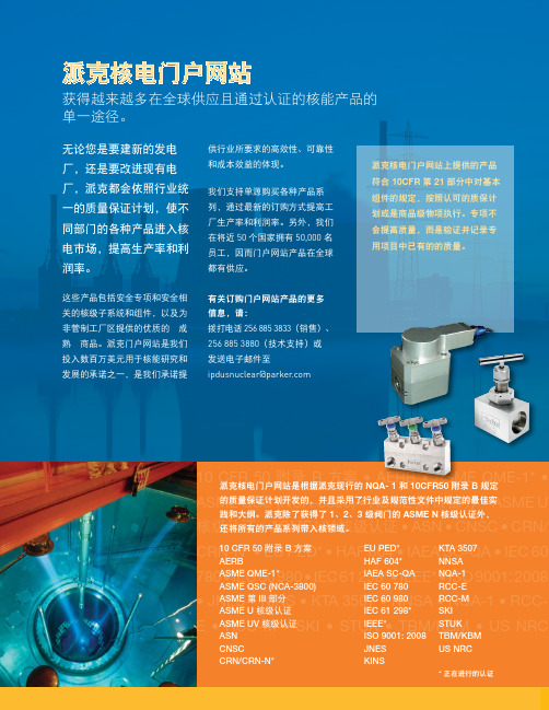
10 CFR 50 • AERB • ASME QME-1* • ASME QSC (NCA-3800) • ASME 第 III 部分 • ASME U核级认证核级认证 • ASN • CNSC CRN-N* HAF 604 • IAEA SC-QA 780 298* • IEEE* • ISO 9001: •E 派克核电门户网站无论您是要建新的发电厂,还是要改进现有电厂,派克都会依照行业统一的质量保证计划,使不同部门的各种产品进入核电市场,提高生产率和利润率。
这些产品包括安全专项和安全相关的核级子系统和组件,以及为非管制工厂区提供的优质的“成熟”商品。
派克门户网站是我们投入数百万美元用于核能研究和发展的承诺之一,是我们承诺提获得越来越多在全球供应且通过认证的核能产品的单一途径。
供行业所要求的高效性、可靠性和成本效益的体现。
我们支持单源购买各种产品系列,通过最新的订购方式提高工厂生产率和利润率。
另外,我们在将近 50 个国家拥有 50,000 名员工,因而门户网站产品在全球都有供应。
有关订购门户网站产品的更多信息,请:拨打电话 256 885 3833(销售)、256 885 3880(技术支持)或 发送电子邮件至 ipdusnuclear@parker .com派克核电门户网站是根据派克现行的 NQA- 1 和 10CFR50 附录 B 规定的质量保证计划开发的,并且采用了行业及规范性文件中规定的最佳实3 级阀门的 ASME N 核级认证外,派克核电门户网站上提供的产品符合 10CFR 第 21 部分中对基本组件的规定,按照认可的质保计划或是商品级物项执行。
专项不会提高质量,而是验证并记录专用项目中已有的的质量。
EU PED*HAF 604*IAEA SC-QA KTA 3507NNSANQA-1Parker Hannifin Ltd.Tachbrook Park DriveTachbrook Park,Warwick, CV34 6TU英国电话:+44 (0) 1926 317 878传真:+44 (0) 1926 317 855********************欧洲、中东和非洲AE – 阿联酋,迪拜电话:+971 4 8127100********************AT – 奥地利,维也纳新城电话:+43 (0)2622 23501-0*************************AT – 东欧,维也纳新城电话:+43 (0)2622 23501 900****************************AZ – 阿塞拜疆,巴库电话:+994 50 2233 458****************************BE/LU – 比利时,尼韦尔电话:+32 (0)67 280 900*************************BY – 白俄罗斯,明斯克电话:+375 17 209 9399*************************CH – 瑞士,埃托瓦电话:+41 (0)21 821 87 00*****************************CZ – 捷克共和国,Klecany电话:+420 284 083 111*******************************DE – 德国,卡尔斯特电话:+49 (0)2131 4016 0*************************DK – 丹麦,巴勒鲁普电话:+45 43 56 04 00*************************ES – 西班牙,马德里电话:+34 902 330 001***********************FI – 芬兰,万塔河电话:+358 (0)20 753 2500parker. ****************FR – 法国,Contamine s/Arve电话:+33 (0)4 50 25 80 25************************GR – 希腊,雅典电话:+30 210 933 6450************************HU – 匈牙利,布达佩斯电话:+36 23 885 470*************************IE – 爱尔兰,都柏林电话:+353 (0)1 466 6370*************************IT – 意大利,Corsico (MI)电话:+39 02 45 19 21***********************KZ – 哈萨克斯坦,阿拉木图电话:+7 7273 561 000****************************NL – 荷兰,奥尔登扎尔电话:+31 (0)541 585 000********************NO – 挪威,阿斯克尔电话:+47 66 75 34 00************************PL – 波兰,华沙电话:+48 (0)22 573 24 00************************PT – 葡萄牙,莱萨·达·帕尔梅拉电话:351 22 999 7360**************************RO – 罗马尼亚,布加勒斯特电话:+40 21 252 1382*************************RU – 俄罗斯,莫斯科电话:+7 495 645-2156************************SE – 瑞典,Spånga电话:+46 (0)8 59 79 50 00************************SK – 斯洛伐克,班斯卡·比斯特里察电话:+421 484 162 252**************************SL – 斯洛文尼亚,新梅斯托电话:+386 7 337 6650**************************TR – 土耳其,伊斯坦布尔电话:+90 216 4997081************************UA – 乌克兰,基辅电话:+380 44 494 2731*************************UK – 英国,沃里克电话:+44 (0)1926 317 878********************ZA – 南非,坎普顿公园电话:+27 (0)11 961 0700*****************************北美地区CA – 加拿大,安大略省米尔顿电话:+1 905 693 3000US – 美国,克利夫兰电话:+1 216 896 3000亚太地区AU – 澳大利亚,城堡山电话:+61 (0)2-9634 7777CN – 中国,上海电话:+86 21 2899 5000HK – 香港电话:+852 2428 8008IN – 印度,孟买电话:+91 22 6513 7081-85JP – 日本,东京电话:+81 (0)3 6408 3901KR – 韩国,首尔电话:+82 2 559 0400MY – 马来西亚,莎阿南电话:+60 3 7849 0800NZ – 新西兰,惠灵顿电话:+64 9 574 1744SG – 新加坡电话:+65 6887 6300TH – 泰国,曼谷电话:+662 186 7000-99TW – 台湾,台北电话:+886 2 2298 8987南美AR – 阿根廷,布宜诺斯艾利斯电话:+54 3327 44 4129BR – 巴西,圣若泽杜斯坎普电话:+55 800 727 5374CL – 智利,圣地亚哥电话:+56 2 623 1216MX – 墨西哥,阿波达卡电话:+52 81 8156 6000核电门户网站手册 M&K 12/10 1M派克授权的本地经销商© 2010 派克汉尼汾公司派克全球办事处联系信息欧洲产品信息中心免费电话:00 800 27 27 5374(AT, BE, CH, CZ, DE, DK, EE, ES, FI, FR, IE,IL, IS, IT, LU, MT, NL, NO, PL, PT, RU, SE,SK, UK, ZA)– 一点的方式。
- 1、下载文档前请自行甄别文档内容的完整性,平台不提供额外的编辑、内容补充、找答案等附加服务。
- 2、"仅部分预览"的文档,不可在线预览部分如存在完整性等问题,可反馈申请退款(可完整预览的文档不适用该条件!)。
- 3、如文档侵犯您的权益,请联系客服反馈,我们会尽快为您处理(人工客服工作时间:9:00-18:30)。
Engineering StandardSAES-J-903 28 November, 2001 Intrinsically Safe SystemsInstrumentation Standards Committee MembersAl-Awami. L.H., ChairmanAl-Khalifa, A.H.Alqaffas, S.A.Al-Shiha, A.M.El-Hage, M.S.Fadley, G.L.Falkenberg, A.R.Fritz, R.H.George, N.A.Hartman, R.A.Hazelwood, W.P.Khan, M.A.Mahmood, B.Nawaz, S.M.Salars, D.S.Trembley, R.J.Saudi Aramco DeskTop StandardsTable of Contents1 Scope (2)2 Conflicts and Deviations (2)3 References (2)4 Definitions (3)5 Equipment (4)6 Procedure (5)7 I.S. System Design Package (5)8 Installation (7)9 Modification of Intrinsically Safe Systems (11)10 Maintenance and Testing (11)Previous Issue: 31 January, 2001 Next Planned Update: 1 December, 2004Next Planned Update: 1 December, 2004 Intrinsically Safe Systems 1 Scope1.1 "Intrinsic safety" is a design and construction method that can be applied to electricalinstruments and their interconnection wiring for safe use in a hazardous (classified) location.1.2 This standard defines the conditions to be fulfilled to meet Saudi Aramco requirements forintrinsically safe (I.S.) systems. Any deviation from this standard shall be approved inwriting by the General Supervisor, Process Instrumentation Division, P&CSD.1.3 This standard is not intended as a guide for equipment design.1.4 I.S. systems shall only be used where other methods of protection are impractical (e.g., shiploading arms and inline analyzers). This standard shall be followed in its entirety afterobtaining prior permission to use an intrinsically safe system from the General Supervisor,Process Instrumentation Division, P&CSD.The use of Intrinsic Safety as a protection method is required for all instruments locatedwithin Class I, Zone 0 areas. Electrical hazardous areas are classification per SAES-B-068.Intrinsically Safe circuits that are part of third party certified systems, are factory installed,and require no modification in the field, are acceptable without prior approval of PID.2 Conflicts and Deviations2.1 Any conflicts between this Standard and other applicable Saudi Aramco EngineeringStandards (SAESs), Materials System Specifications (SAMSSs), Standard Drawings(SASDs), or industry standards, codes, and forms shall be resolved in writing by theCompany or Buyer Representative through the General Supervisor, Process InstrumentationDivision, P&CSD of Saudi Aramco, Dhahran.2.2 Direct all requests to deviate from this standard in writing to the Company or BuyerRepresentative, who shall follow internal company procedure SAEP-302 and forward suchrequests to the General Supervisor, Process Instrumentation Division, P&CSD of SaudiAramco, Dhahran.3 ReferencesThe latest edition or revision of the following standards, specifications, codes, forms, and drawings shall, to the extent specified herein, form a part of this standard.3.1 Saudi Aramco ReferencesSaudi Aramco Engineering ProcedureSAEP-302 Instructions for Obtaining a Waiver of a Mandatory SaudiAramco Engineering RequirementSaudi Aramco Engineering StandardsSAES-B-008 Restrictions to Use of Cellars, Pits, and TrenchesNext Planned Update: 1 December, 2004 Intrinsically Safe SystemsSAES-B-068 Electrical Area ClassificationsSAES-J-005 Instrumentation Drawings and FormsSAES-J-902 Electrical Systems for InstrumentationSAES-O-126 Blast Resistant Control BuildingsSAES-P-100 Basic Power System Design Criteria3.2 Industry Codes and StandardsThe International Society for Measurement and ControlISA RP12.6 Wiring Practices for Hazardous (Classified) LocationsInstrumentation Part 1: Intrinsic SafetyISA RP12.2.02 Recommendations for the Preparation, Content, andOrganization of Intrinsic Safety Control Drawings ISA TR12.2 Intrinsically Safe System Assessment Using the EntityConceptNational Electrical Manufacturers AssociationNEMA 250 Enclosures for Electrical Equipment(1000 Volts Maximum)National Fire Protection AssociationNFPA 70 National Electric Code (NEC)Article 500, Hazardous (Classified) LocationsArticle 504, Intrinsically Safe SystemsArticle 505, Class I, Zone 0, 1, and 2 Locations4 DefinitionsAssociated Apparatus:Apparatus in which the circuits are not necessarily intrinsically safe themselves, but which affect the energy in the intrinsically safe circuits and are relied upon to maintain intrinsic safety. The associated apparatus represents the primary means to limit energy to field devices located in hazardous areas. It often consists of an intrinsic safety barrier or isolator.Commentary Note:Active galvanic isolators are the preferred type of associated apparatus.Control Drawing: A drawing or other documentation provided by the manufacturer of the intrinsically safe or associated apparatus that details the allowed interconnections between the intrinsically safe and associated apparatus.Fault: A defect or electrical breakdown of any component, spacing or insulation that alone or in combination with other faults, may adversely affect the electrical or thermal characteristics of the intrinsically safe circuit. If a defect or breakdown leads to defects or breakdowns in other components, the primary and subsequent defects and breakdowns are considered to be a single fault.Next Planned Update: 1 December, 2004 Intrinsically Safe Systems Intrinsically Safe Apparatus: Apparatus in which all the circuits are intrinsically safe.Intrinsically Safe Circuit: A circuit in which any spark or thermal effect, produced either normally or in specified fault conditions, is incapable, under the test conditions prescribed, of causing ignition of a mixture of flammable or combustible material in air in its most easily ignited concentration.Intrinsically Safe System: An assembly of interconnected intrinsically safe apparatus, associated apparatus, and interconnection cables in which those parts of the system that may be used in hazardous (classified) locations are intrinsically safe circuits.Intrinsic Safety Ground Bus: A grounding system which has a dedicated conductor separate from the power system and which is reliably connected to a ground electrode in accordance with Article 250 of the NEC.Normal Operation: Intrinsically safe apparatus or associated apparatus conforming electrically and mechanically with its design specification.Simple Apparatus: A device which will not generate or store more than 1.2 V, 0.1 A, 25 mW, or 20 microJ. Examples are switches, thermocouples, light-emitting diodes, and resistance temperature detectors (RTDs).5 Equipment5.1 Only equipment, apparatus or devices that have been certified, labeled or listed asintrinsically safe (I.S.) by a third party testing laboratory shall be used or installed under thisstandard.Exception:If the field device is classified as simple apparatus, certification is not required.5.2 As third party testing laboratories, only the agencies listed in SAES-P-100, Table 1 areacceptable under this standard.For equipment, devices, or apparatus certified as intrinsically safe, only those that arecertified as category EEX or AEX "ia" shall be used.Commentary Note:The identifying letter for intrinsic safety is "i" followed by either "a" or "b," identifyingwhether the equipment is suitable for Zone 0 (ia) or Zone 1 (ib). Intrinsically safesystems are limited by this standard to those certified "ia" to simplify the selectionprocess and to ensure that an I.S. system is safe to install in all locations (Zone 0, 1,or 2).6 ProcedureThe proponent/PMT shall notify the General Supervisor, Process Instrumentation Division, P&CSD of the intent to use an intrinsically safe system.Next Planned Update: 1 December, 2004 Intrinsically Safe Systems6.1 The proponent/PMT shall prepare an I.S. System design package and submit to ProcessInstrumentation Division, P&CSD for system approval during engineering design.6.2 When the installation is complete, the I.S. system shall be inspected by ProcessInstrumentation Division, P&CSD and Inspection Department.6.3 Although the above procedure is not required for factory installed Intrinsically Safe systems(ref. Note in Section 1.4), all certification documents listed in Section 7 shall be provided aspart of the package unit documentation.7 I.S. System Design PackageThe I.S. system design package shall consist of the following documentation:7.1 Electrical area classification drawing.7.2 Plan drawing showing the overall I.S. system from the instruments in the hazardous areas tothe instruments in the non-hazardous area (usually the control room). For sake of clarity, thedrawing shall show the I.S. system only.Demarcation lines between the non-hazardous (safe) area and the hazardous area portions ofsystem shall be clearly shown. The respective areas shall be labeled "non-hazardous (safe)"and "hazardous area".7.3 Typical loop diagrams showing termination assignments in junction boxes and marshallingpanels.7.4 I.S. System Certification InformationA System Control Drawing shall be provided including all Entity Concept parameters foreach component in the intrinsically safe system. I.S. system control drawings shall beprepared in accordance with ISA RP12.2.02. The I.S. system control drawing shall beincluded as a separate sheet of the associated Instrument Loop Drawing (ILD), ref.SAES-J-005.The Certifying agency, Certificate number, and Date of certification shall be supplied foreach component in the intrinsically safe system.Exception:If the field device is classified as simple apparatus, certification of the device itselfis not required. However, all devices included in the Intrinsically Safe loop, shall beshown on the System Control Drawing.To assess the intrinsic safety of the interconnected equipment, the entity parameters shall becompared (including the calculated interconnecting cable capacitance and inductance) inaccordance with ISA TR12.2. Entity parameter calculations shall be submitted with the I.S.system design package for Process Instrumentation Division, P&CSD approval.Commentary Note:Next Planned Update: 1 December, 2004 Intrinsically Safe Systems The I.S. system "control drawing" consolidates the entity parameters for theintrinsically safe field instrument and the associated apparatus as well as theallowable capacitance and inductance of the interconnecting cables. Having thisinformation on a single drawing referenced to the Instrument Loop Drawing (ILD) iscritical when making modifications to the loop in the future.7.5 Cable/Wire Information7.5.1 Size of individual pair or triad, capacitance per unit length, and inductance per unitlength.Single pair/triad interconnecting cables shall be specified with a minimum conductorsize of 16 AWG.Exception:Multiconductor "home run" cables may be specified with 18 AWGconductor size.7.5.2 Cable length, meters (feet)7.5.3 Insulation RatingInterconnecting cables shall be specified with a minimum insulation rating of 600Volts.7.5.4 Cable manufacturer7.6 Grounding Plan7.6.1 Overall control house grounding plan7.6.2 I.S. system vendor recommended grounding method8 InstallationAs proper installation is critical for intrinsically safe circuits to operate safely, special attention shall be given to the installation requirements below:8.1 Field InstrumentThe intrinsically safe instrument enclosure shall be sealed to provide adequate ingressprotection (NEMA 4X or IP 65).Commentary Note:With Intrinsically Safe systems, the instrument enclosure and wire raceway(conduit, tray, etc.) only provide mechanical protection. Therefore, an instrumentinstalled as Intrinsically Safe does not require an "explosion proof" seal and theinterconnecting cable raceway must only be sealed at the point of exit from thehazardous area if it can transport hazardous gases into the non-hazardous area.Next Planned Update: 1 December, 2004 Intrinsically Safe Systems8.2 Interconnecting wiringTypical instrument wiring consists of a shielded, twisted pair/triad from a field located deviceto the associated apparatus (typically the IS barrier)located in a control room or processinterface building. The interconnecting cables used in an intrinsically safe circuit must beelectrically compatible with the intrinsically safe components being used. See section 7.4 forthe requirement to include cable capacitance and inductance contributions on the systemcertificate or system control drawing.8.2.1 Conductors of intrinsically safe circuits shall not be placed in any raceway, cable tray,or cable with conductors of any non-intrinsically safe circuit.8.2.2 Mechanical protection of the conductors to each individual instrument from thefield-mounted instrument to the field junction box shall be provided in the form ofconduit or steel wire armor and cable tray/channel per SAES-J-902. Where cablesystems are used with tray/channel, the cable shall be well supported throughout itslength and the length of unsupported cable at the field instrument shall not exceed0.5 meters.8.2.3 Dedicated intrinsically safe field termination cabinets (junction boxes) shall beprovided to maintain positive separation of intrinsically safe from non-intrinsicallysafe wiring. Where several intrinsically safe instrumentation loops are involved,individual pair/triad from each instrument located in the field may be routed to acommon field termination cabinet. The field termination cabinet will serve as atransition point from individual pair/triad to a multi-pair/triad cable. Multi-corecables shall not combine intrinsically safe and non-intrinsically safe signals.Field termination cabinets (junction boxes) shall be NEMA Type 4X or IP 65(reference NEMA Standards Publication No. 250).8.2.4 Multi-pair/triad cables shall be routed from the field termination cabinets (junctionboxes) to the control room or process interface building in cable trays, in conduits, orby direct burial cable provided the cable is approved for cable tray use or for directburial. Cables shall be sealed against the passage of gas and vapors as required bythe National Electrical Code NFPA 70, SAES-B-008, and SAES-O-126.8.2.5 The standard practice of separating thermocouple, 4-20 milliamp, and digital alarmsignals shall be observed. This segregation shall be maintained in the field viadedicated, intrinsically safe field junction boxes. Signal segregation shall bemaintained up to the marshalling panels, where signals may be consolidated to theextent specified in SAES-J-902.Care shall be taken to avoid locating interconnecting cables containing intrinsicallysafe circuits close to overhead power distribution lines or heavy current carryingcables. Refer to SAES-J-902 for minimum spacing requirements between parallelcable runs of different signal types.Commentary Note:The associated apparatus (I.S. barrier) in an Intrinsically Safe loop onlyNext Planned Update: 1 December, 2004 Intrinsically Safe Systemsprotects the field device and interconnecting wiring from unsafe voltagelevels on the controls system side of the "non-hazardous" terminals.Positive separation between Intrinsically Safe interconnecting cables andnon-Intrinsically Safe conductors ensures that the Intrinsically Safety of theloop is not compromised by a fault on the field side of the associatedapparatus "hazardous area" terminals.8.3 Termination8.3.1 I.S. system wiring shall be terminated in dedicated marshalling cabinets orcompartments within marshalling cabinets that house the associated apparatus. I.S.cables shall enter the cabinet through cable entries completely separate and oppositefrom the non-intrinsically safe connecting cables to the control system.Cabinets that contain the associated apparatus shall be located within air-conditionedanalyzer shelters, process interface buildings, or control rooms.Exception:The associated apparatus may be installed in the field when supplied aspart of the vendors standard product offering certified for use in theintended hazardous area.Commentary Note:The associated apparatus (barrier) may be installed within a field mounted,NEMA 4X enclosure provided the certification mark on the device identifiesit may be safely installed in the intended hazardous location. Thecertification marking on the associated apparatus is completely separatefrom the entity parameters listed for the output terminals (used to matchthe associated apparatus with the intrinsically safe instrument located inthe hazardous area).8.3.2 The I.S. cables from the field instrument shall be terminated on the "hazardous area"terminations of the associated apparatus and shall be secured or tie-wrappedseparately from the non-intrinsically safe cables terminated on the opposite end "safearea" terminals of the associated apparatus. A minimum of 2 inches (50 mm) shallbe maintained between the I.S. and non-I.S. cables within the cabinet that containsthe associated apparatus.8.3.3 All spare wires shall be terminated at terminal blocks and grounded to the intrinsicsafety ground bus. Unused wires shall also be insulated at their hazardous area ends.8.3.4 The minimum clearances between terminals of intrinsically safe circuits and anygrounded metal shall be 3 mm (81 inch), unless that terminal is intended to begrounded. The clearance between two terminals of different intrinsically safecircuits shall be at least 6 mm (¼ inch).8.4 Grounding8.4.1 I.S. system grounding shall conform to the I.S. system vendor's groundingNext Planned Update: 1 December, 2004 Intrinsically Safe Systems recommendations.All intrinsically safe circuit grounds shall be connected to the grounding system withdedicated I.S. grounding conductors separate from non-intrinsically safe, orequipment, or power grounds.Commentary Note:In the case of Radar Tank Gauging (RTG) systems, the tank groundingsystem (or tank structure) serves as both the intrinsically safe ground andthe electrical safety ground. The installation of a separate I.S. ground rodat each tank is not required.8.4.2 In cabinets housing the associated apparatus, the intrinsic safety ground bus shall beconnected to a node in the overall plant ground grid by dedicated, redundant,insulated copper cables not smaller than #4 AWG. To identify the intrinsically safegrounding conductors as being different from other ground connections, thegrounding conductor insulation color shall be green with blue tracer (or banded withblue tape).Where screens/shields are used, they shall be covered by an outer insulating sheath.They shall be grounded at the associated apparatus intrinsic safety ground point andinsulated at the hazardous area end. Where screened multipair/multitriad cablesinterconnect within field junction boxes with individual screened pair/triad cables,insulated terminals shall be provided for the ongoing continuity of thescreens/shields.8.4.3 When zener diode type barriers are used, the maximum resistance between thefarthest point on the intrinsic safety barrier ground and the plant grounding system(the point at which the incoming electricity supply neutral is grounded) shall notexceed 1 Ohm.Commentary Note:The low impedance (1 Ohm or less) ground connection is not requiredwhen active galvanic isolators are used as the associated apparatus.8.4.4 All metal enclosures for intrinsically safe circuits shall be grounded to the plantgrounding system with a minimum of #4 AWG copper wire with green insulation.8.4.5 All metal cable trays used for intrinsically safe wiring shall be grounded to the plantgrounding system with a minimum of #4 AWG copper wire with green insulation.8.4.6 Cable protective armor, if used, shall be grounded to plant grounding system at thefield junction box.8.5 Identification8.5.1 All intrinsically safe system components shall be so identified.8.5.2 All junction boxes, cable trays, conduits, cables, cabinets, and instrument housingsNext Planned Update: 1 December, 2004 Intrinsically Safe Systems shall be labeled as containing intrinsically safe circuits or equipment. The means ofidentification shall be visible after installation. Label spacing on cable tray, conduit,and interconnecting cables shall not exceed 25 feet (8 meters).Commentary Note:Self-sticking markers are recommended (e.g., Brady Polyester 0.112 mmthickness, permanent acrylic adhesive 0.026 mm, clear over laminatetype). Specify light blue letters on white background for the controlcabinets, conduit runs, and local junction boxes (¾ inch x 8 inch lengthcolor field with ½ inch letter height).8.5.3 Light blue color coding shall be used to identify intrinsically safe wiring. Thepreferred practice is to specify intrinsically safe interconnecting cables with a blueouter jacket. Alternatively, blue sleeves slipped over the jacket at all points oftermination may be used to identify I.S. wiring.9 Modification of Intrinsically Safe Systems9.1 A log shall be maintained, by the responsible proponent organization, of all modifications toexisting I.S. systems. Drawings shall be modified and the design approved using EntityConcept parameters by a qualified designer (Reference ISA RP12.6 and ISA TR12.2).9.2 Only devices, apparatus, and equipment that have been approved, certified, or labeled asIntrinsically Safe shall be used when existing Intrinsically Safe instrumentation loops orsystems are modified.Exception:If the field device is classified as a simple apparatus, certification is not required.9.3 Installation shall be in accordance with existing system documentation (System ControlDrawing) and manufacturers' instructions.10 Maintenance And Testing10.1 An I.S. system may be tested and maintained under live (working) conditions provided theportable test equipment used has been certified and approved as intrinsically safe for theparticular atmospheric hazard. Otherwise, a hot work permit shall be issued.10.2 Only safety barriers/isolators of the same type, make, or catalog number shall be used toreplace defective safety barriers/isolators.10.3 Only devices of the same make, type, and catalog number or replacement recommended bythe manufacturer shall be used to replace any device in the system.10.4 Any changes, additions/deletions of components to/from a loop, shall be recorded at theoperating facility in the appropriate Saudi Aramco drawings.Document Responsibility: Instrumentation SAES-J-903 Issue Date: 28 November, 2001Next Planned Update: 1 December, 2004 Intrinsically Safe Systems Revision Summary28 November, 2001 Major revision.Page 11 of 11。