FT5346DQQ_General_APP_SCH_Rev0.4_Preliminary
电机控制开发套件motorBench 2.25说明书
Dashboard/…/motorBench 2.25 ReleasemotorBench 2.25.0 Release NotesCreated by Fernando Garibaldi, last modified by Jason Sachs 2 minutes agoOverview of motorBench® Development SuiteWhat’s NewSystem RequirementsSupported HardwareHigh-voltage hardwareOther hardware required with both low-voltage and high-voltage setupsInstalling motorBench® Development Suite 2.25.0RepairsMotor Control Fixed IssuesChanges since revision 2.15Known IssuesMotor Control IssuesLimitationsSupported DevicesSoftware LimitationsMotor Control LimitationsSupported Motor ParametersCustomer SupportThe Microchip Web SiteAdditional SupportOverview of motorBench® Development SuiteMicrochip motorBench Development Suite is a graphical, interactive development environment designed to help motor control engineers to design and implement motor control systems, from very basic to very sophisticated ones.motorBench® Development Suite allows the user to:configure a motor systemmeasure motor parameterstune the controller gainsgenerate code to spin the motorWhat’s New1. Motor Control Application Framework (MCAF) R5 – see MCAF User's Guide for more information.a. Added support for dsPIC33CK256MP508b. Added Angle-tracking PLL (ATPLL) supportc. Improved Customize page support in motorBench2. Customizea. Allow advanced customization of MCAF code generation3. Measurea. Updated fault handing logic to detect if an invalid load is connected to the inverter before starting motor parameter measurement or Board calibrationb. Improvements to support motors with large values of stator inductancec. Improvements to support motors with large inertia and high cogging torque4. MCC Integrationa. Improved support for MCC-generated peripheral and system initialization code5. Device Supporta. Added support for dsPIC33CK256MP508i. This device is not yet supported by the motor parameter measurement featureSystem RequirementsMPLAB X 5.30 or later.XC16 compiler version:Firmware generated by motorBench® Development Suite has been tested with XC16 1.41.33EP devices: XC16 1.36 or later are expected to work with motorBench®Development Suite but have not been extensively tested.33CK devices: Either of the following is required:XC16 1.50 or laterXC16 1.41 with DFP 1.2.66 or laterMPLAB Code Configurator®(MCC) Plugin Version 3.95.0 or laterPIC24/dsPIC33/PIC32MM library 1.166.0 or laterSupported HardwareThis release of motorBench®Development Suite supports both low-voltage and high-voltage setups.Low-voltage hardware1. dsPICDEM MCLV-2 Development Board [Part Number: DM330021-2]2. dsPIC33EP256MC506 External Op Amp Motor Control PIM [Part Number: MA330031-2] with silicon revision A8 or dsPIC33CK256MP508 External Op Amp Motor Control Pim[Part Number: MA330041-1].3. A three phase PMSM or BLDC motor that is compatible with 24V, such as the Hurst 24V BLDC motor DMA0204024B101 [Part Number: AC300022].4. 24V power supply [Part Number: AC002013] - ensure this connects to AC mains using a 2-prong cable. If you have an AC002013 with a 3-prong cable, please contact Microchip.High-voltage hardware1. dsPICDEM MCHV-2 Development Board [Part Number: DM330023-2] or dsPICDEM MCHV-3 Development Board [Part Number: DM330023-3]AC mains voltages 120VAC 60Hz and 220VAC 50Hz have been tested.2. dsPIC33EP256MC506 External Op Amp Motor Control PIM [Part Number: MA330031-2] with silicon revision A8 or dsPIC33CK256MP508 External Op Amp Motor Control Pim[Part Number: MA330041-1].3. A three phase PMSM or BLDC motor that is compatible with rectified AC mains voltage, such as the Leadshine 400W BLDC motor EL5-M0400-1-24 [Part Number: AC300025].Other hardware required with both low-voltage and high-voltage setups1. A USB-to-logic-level-UART converter from the following list:a. Saelig USB-COM-U or USB-COM-U13b. TRENDnet TU-S9 v2.02. Programming tool - one of the following tools: Real ICE, ICD33. Board calibration load resistors - this is optional, please see motorBench® Development Suite User's Guide document for more detailsInstalling motorBench ® Development Suite 2.25.0To install the MPLAB ® Code Configurator v3.95 Plugin1. In the MPLAB® X IDE, select Plugins from the Tools menu2. Select the Available Plugins tab3. Check the box for the MPLAB® Code Configurator v3, and click on InstallTo install different peripheral library version or motorBench ® Development Suite version when connected to internet1. Create a project with dsPIC33EP256MC506 or dsPIC33CK256MP508, or use the sample project.2. Open MPLAB® Code Configurator3. In the Versions tab under PIC24/dsPIC33/PIC32MM MCUs, find the multiple library versions (loaded version is indicated by the green check mark)4. Right-click on the required version of the library and select Mark for Load5. In the Versions tab under motorBench ® Development Suite find the multiple library versions (loaded version is indicated by the green check mark)6. Right-click on the 2.25.0 version of the library and select Mark for Load7. Click on Load Selected Libraries button to load the marked libraries.To install different peripheral library version or motorBench® Development Suite version when not connected to internet1. In the MPLAB® X IDE, select Options from the Tools menu2. Select Plugins tab3. Click on Install Library4. Add pic24-dspic33-pic32mm_v1.166.mc3lib5. Add motorBench_2.25.0.mc3lib6. Restart MPLAB® X IDERepairsMotor Control Fixed IssuesChanges since revision 2.15The following aspects of motorBench® Development Suite and the Motor Control Application Framework (MCAF) have been updated:MCAF has been updated to R5, includingChanges in R2:Support for DC link compensationSupport for overmodulationSupport for wider range of low-voltage motorsUpdated HAL for future MCHV2 supportUpdated Motor Control LibraryNumerous minor fixesChanges in R3:MCC system module compatibilityMCHV-2 and MCHV-3 supportInverter maximum current now has a 1:1 ratio with the maximum commanded dq-frame current of the drive, operating in FOC (in R2 this incorporated a deratingfactor)Other minor fixesChanges in R4:MCC peripheral supportParameter customizationQuadrature encoder supportAdded new startup method (Weathervane startup)Other minor fixesChanges in R5:Added device support for dsPIC33CK256MP508Added Angle-tracking PLL (ATPLL) sensorless estimatorImproved motorBench Customize page supportOther minor fixesSections in this release notes affected:Other RequirementsLimitationsSupported Motor ParametersKnown IssuesPlease note:We do not recommend using the MCP2200 USB to RS232 Demo Board [Part number: MCP2200EV-VCP ] with this release of motorBench® Development Suite.While testing, we have observed more frequent occurrence of a serial communication timeout issue while running motor parameter measurement using this cable.See Known Issues section of this document for more information (MCGUI-1141)Motor parameter measurement is only supported on dsPIC33EP256MC506 device.Issue Key Summary WorkaroundMBPLAN-673Serial port does not get closed programmatically when MCC exits during motor parametermeasurementIf you exit SC during execution, restart MPLAB X.MBPLAN-932Exception during attempted creation of a runtime properties class No workaround needed, this issue doesn't have an impact on thefunctionality.MBPLAN-984Improve error reporting for SC build errors in the event of a code generation failureMBPLAN-1095Switching projects after loading motorBench erroneously allows motorBench code to generate for new projectMBPLAN-1160"Import Motor" and "Export Motor" buttons can be clicked multiple times, opening multiple dialog boxesMotor Control IssuesIssue Key SummaryDB_MC-411Current calibration happens only once (at part reset) rather than upon entry to MCSM_RESET stateDB_MC-560Speed controller exhibits chattering behavior at voltage saturation hysteresis boundary (MCAF)DB_MC-978"Soft start" gate drive in board_service.c has duty cycle that is too smallDB_MC-1092PLL estimator may not converge into rotor reference frame while using the Classic startup method in MCAFDB_MC-1396PLL calculations in code generation do not allow motor.velocity.nominal to be more than 1250Hz electrical (=20kHz/8/2)DB_MC-1415With some motors and 12V operation, increased velocity margin improves startup but creates unstable estimatorDB_MC-1430Quanum MT4012 unstable in closed-loop operation at 4200 RPM speed and aboveDB_MC-1491With Quanum MT4012, MCAF may not detect stallDB_MC-1492Quanum MT4012 Stalls on pressing 'S3'(reverse) at low speeds and on changes to speed command potentiometerDB_MC-1495Anaheim BLY342D-24V-3000, BLY342D-48V-3200 motors creates hardware over-current during stall-detect testingDB_MC-1521Closed loop speed step response overshoot - MCHV2, Leadshine 400DB_MC-1892Some motors with extreme parameters may produce out-of-range error for stall_detect.group.timerCountsVarianceDetect (detected in Monte Carlo analysis)DB_MC-1920Board service isrCount-based timing is not guaranteedDB_MC-1922LED patterns not displayed when in the TEST_DISABLE or TEST_ENABLE statesDB_MC-2122BLWS232D motor startup in QEI mode causes a false detect for stall-detectionDB_MC-2213Deadtime needs to be changed in both MCC and motorBench to affect codeDB_MC-2275Large current rampup times may not start (STARTUP_TORQUE_RAMPUP_RATE = 0)DB_MC-2309QEI tracking loop Kp and Ki produce out-of-range errors for low-speed motorsDB_MC-2323Weathervane transition state should not have active damping enabledDB_MC-2387DC link voltage measurement may have too much phase delay for MCAF DC link compensation to work effectivelyDB_MC-2606MCC-generated code has incorrect IESO/FNOSC config bits for 33CKDB_MC-2671MCAF_CaptureTimestamp calls incorrect timer function for 33CK devicesDB_MC-2785Current sense signal integrity issue with 33CK during overmodulationLimitationsSupported DevicesmotorBench® Development Suite supports these devices:1. dsPIC33EP256MC5062. dsPIC33CK256MP508Software LimitationsmotorBench® Development Suite is tested for serial communication using Windows 7 and Windows 10 platforms. Other platforms may work with standard baud rates, but this operation has not yet been verified.Motor Control LimitationsFollowing are the known limitations for this release of motorBench® Development Suite:1. One mechanical load - constant load. This represents a mechanical load with constant inertia, viscous damping, and friction. The velocity control loop can generally rejectexternal disturbance torques, within the rated current of the motor and board, and within the bandwidth of the velocity control loop. Mechanical loads with time-varying or angle-varying inertia, viscous damping, and friction, such as a blower, compressor, or pump, are currently not supported.2. One motor type - PMSMMCLV-2:The reference motor is the Nidec Hurst motor DMA0204024B101 (MicrochipDirect part number AC300022). Microchip has also validated motorBench® DevelopmentSuite (including motor parameter measurement) with motors with parameters plotted below. Please also read the following section on Supported Motor Parameters. IfmotorBench® Development Suite is unable to spin a motor successfully, please contact Microchip staff for additional assistance.(Note: Mechanical time constant (2/3)×JR/Ke² represents the time constant of velocity acceleration under an open-loop synchronous-frame voltage step, neglecting the effects of inductance, with J, R, and Ke expressed in canonical metric units. R is expressed as line-neutral resistance = half of line-line resistance, and Ke is expressed as V/(rad/s) line-neutral zero-peak = Vrms/KRPM (line-line) × 0.007796968)MCHV-2/MCHV-3:The reference motor is the Leadshine 400W motor EL5-M0400-1-24 (MicrochipDirect part number: AC300025). Microchip has validated motorBench® DevelopmentSuite (including motor parameter measurement) with motors with parameters plotted below. Please also read the following section on Supported MotorParameters. If motorBench® Development Suite is unable to spin a motor successfully, please contact Microchip staff for additional assistance.3. Boarda. dsPICDEM™ MCLV-2 development board. This release of motorBench® Development Suite is compatible with modifications to the board to alter its rated current orvoltage. Contact your local Microchip office to obtain the document "Using MCLV-2 with motorBench® Development Suite to support alternative current and/or voltageratings", which provides guidance for such modifications. Other modifications may not be compatible.b. dsPICDEM™ MCHV-2 and MCHV-3 development boards. This release of motorBench® Development Suite is compatible with unmodified MCHV-2 and MCHV-3development boards.4. Motors should be well-matched to the board and operating voltage. The nominal DC link voltage of the MCLV-2 board is 24V. This voltage can be changed by cutting jumperJ6 and using an appropriate power supply connected to the appropriate terminals of J7. Use of a mismatched motor (for example, a 12V motor used with a 24V DC link voltage) may cause a hardware over-current fault; in this case motor parameter measurement may fail with the message "Fault Code #10: Undefined Fault". Retry with an appropriate DC link voltage.5. Two PIMs and Two devices - dsPIC33EP256MC506 External OpAmp PIM with silicon revision A8 or dsPIC33CK256MP508 External OpAmp PIM. (Please see the HardwareSetup section of the motorBench User's Guide for important modifications to dsPIC33EP256MC506 External OpAmp PIM for use in MCHV-2 and MCHV-3.)6. One algorithm - FOC7. Estimators - PLL, QEI, ATPLL8. Motor parameter measurement:a. Performance criteria adjustment is not presently supported. This includes adjustment of phase margin and PI phase lag at crossover in the current loop; Microchip hasnot completed validation and documentation of these adjustments.9. Autotuning:a. Performance criteria adjustment of the current loop is not presently supported. This includes adjustment of phase margin and PI phase lag at crossover; Microchiphas not completed validation and documentation of these adjustments.b. Use of performance criteria adjustment of the velocity loop is not fully documented or tested. We recommend not adjusting phase margin or PI phase lag unlessnecessary; cases where this is likely to occur are large inertias where αJ = JR/LK m2 > 10, for which an increase of phase margin is appropriate. Phase margin valuesbetween 70 and 85 degrees are recommended in this case, with larger values providing additional stability at the cost of lower velocity bandwidth.10. Axis management not currently implemented - supports only one axis.11. Code generation:a. PWM switching frequency is fixed at 20kHz and does not reflect the value entered under Board parametersb. Integration with external user-supplied code may involve substantial changes. Some guidelines for this are given in the documentation for the Motor ControlApplication Framework. While it is possible to integrate the code generated from motorBench® Development Suite with external code, it is the responsibility of the end user to validate this combination.12. Required compiler settings:a. Optimization-O1 or greater; -O0 and -Os will both compile without errors but do not execute fast enough to complete within the 50 microsecond ADC ISR. Note: at higheroptimization levels, in-circuit debugging using MPLAB X will behave unreliably with respect to breakpoints and single-stepping through C code.The "Omit frame pointer" and "Unroll loops" settings must be enabled.b. Memory model:Large data model (handles using pointers, not direct addressing, to allow for more than 8K of program variables)Small scalar modelc. Additional options:-Wno-volatile-register-var -finlined. Test harness: In order for the test harness to be enabled, the symbols MCAF_TEST_PROFILING and MCAF_TEST_HARNESS should be defined.13. Recommended compiler settings:a. Additional options:-WundefSupported Motor ParametersSince version 2.15, motorBench®Development Suite supports a wide range of motors, subject to the following notes:Ranges of motor parameters (including rated values and computed metrics) must be within the limits noted in either range-limits-mclv2.html or range-limits-mchv2.html.These ranges were tested to ensure that code generation produced firmware constants that were within bounds.Motor parameter measurement does not need to complete successfully but valid motor parameters are required. Some motors may have too low of an inductance or resistance, and may fail motor parameter measurement.Other particular issues that may cause incompatibility with motorBench®Development Suite includeLarge inertia values – in this case, increasing voltage loop phase margin may prevent stability problems. (See "Autotuning" in the Limitations section of this document.) Rotor magnetic saliency – if there are significant differences between Ld and Lq (>10% difference) then some of the MCAF algorithms may not work optimally. Highermismatch between Ld and Lq is typically found in interior-permanent magnet (IPM) motors, and is an intentional feature of the design. See the MCAF User's Guide for more information.Large back-EMF harmonics – a quasi-sinusoidal back-emf is assumedIssues involving individual motor control algorithms, such as PLL estimator, motor startup, or stall detectionHigh cogging torqueMismatch between motor and drive (namely using a motor with current and/or voltage requirements significantly different from that of the hardware) Microchip cannot guarantee that motorBench®Development Suite will work correctly with all motors. If a particular motor does not work properly, please contact the MCU16 Motor Control Team for further guidance.Customer SupportThe Microchip Web SiteMicrochip provides online support via our web site at . This web site is used as a means to make files and information easily available to customers. Accessible by using your favorite Internet browser, the web site contains the following information:Product Support – Data sheets and errata, application notes and sample programs, design resources, user’s guides and hardware support documents, latest software releases and archived softwareGeneral Technical Support – Frequently Asked Questions (FAQs), technical support requests, online discussion groups/forums (), Microchip consultant program member listingBusiness of Microchip – Product selector and ordering guides, latest Microchip press releases, listing of seminars and events, listings of Microchip sales offices, distributors and factory representativesAdditional SupportUsers of Microchip products can receive assistance through several channels:Distributor or RepresentativeLocal Sales OfficeField Application Engineering (FAE)Technical SupportCustomers should contact their distributor, representative or field application engineer (FAE) for support. Local sales offices are also available to help customers. A listing of sales offices and locations is available on our web site.Technical support is available through the web site at: 。
FT6336U_APP_SCH
PG S39 S38 S37 S36 S35 S34 S33 S32 S31 S30 S29 S28 S27 S26 S25 S24 S23 S22 S21 S20 S19 S18 S17 S16 S15 S14 S13 S12 S11 S10 S9 S8 S7 S6 S5 S4 S3 S2 S1 PG
A
FocalTech
Title
Confidential
FT6336U Application Schematic
Designed by Jonny Kuo Form # : RAE-4-021-A Rev of 1
Size Document Number EX-FT6336U-004-1606-10 A Date: Monday, March 21, 2016 Sheet 1
V
C
FT6336U QFN5X5_48L_P0.35
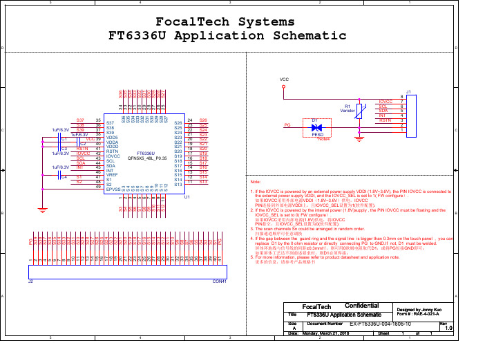
Note: 1. If the IOVCC is powered by an external power supply VDDI (1.8V~3.6V), the PIN IOVCC is connected to the external power supply VDDI, and the IOVCC_SEL is set to 1( FW configure). 如果IOVCC采用外部电源VDDI(1.8V~3.6V)供电,IOVCC PIN连接到外部电源VDDI上,且IOVCC_SEL设置为1(软件配置). 2. If the IOVCC is powered by the internal power (1.8V)supply , the PIN IOVCC must be floating and the IOVCC_SEL is set to 0( FW configure). 如果IOVCC采用内部电源(1.8V)供电,将IOVCC PIN悬空,且IOVCC_SEL设置为0(软件配置). 3. The scan channels Sn could be arranged in random order. 扫描通道顺序可任意调换 4. If the gap between the guard ring and the signal line is bigger than 0.3mm on the touch panel , you can replace D1 by the 0 ohm resistor or directly connecting PG to GND.If not, D1 must be welded. 屏体环地线与信号线的间距≥0.3mm时,则可用0欧姆电阻取代D1,或将PG短接GND即可; 如果屏体工艺达不到前述要求时,则D1必须焊接; 5. For more information, please refer to product datasheet and application note. 更多的信息,请参考产品规格书
Infoprint 250 導入と計画の手引き 第 7 章ホスト
SUBNETMASK
255.255.255.128
Type of service...............: TOS
*NORMAL
Maximum transmission unit.....: MTU
*LIND
Autostart.....................:
AUTOSTART
*YES
: xx.xxx.xxx.xxx
: xx.xxx.xxx.xxx
*
(
)
IEEE802.3
60 1500
: xxxx
48 Infoprint 250
31. AS/400
IP
MTU
1
1
IPDS TCP
CRTPSFCFG (V3R2)
WRKAFP2 (V3R1 & V3R6)
RMTLOCNAME RMTSYS
MODEL
0
Advanced function printing............:
AFP
*YES
AFP attachment........................:
AFPATTACH
*APPC
Online at IPL.........................:
ONLINE
FORMFEED
*CONT
Separator drawer......................:
SEPDRAWER
*FILE
Separator program.....................:
SEPPGM
*NONE
Library.............................:
FT View SE 用户手册_ 5.0_1

FactoryTalk View SE用户手册目录1 章开始..................................................................................................................................... 1-1FactoryTalk系统................................................................................................................... 1-1 FactoryTalk View Site Edition的主要部分 ......................................................................... 1-3 FactoryTalk View Site Edition的主要特点 ......................................................................... 1-4 FactoryTalk View工具 ......................................................................................................... 1-5 罗克韦尔软件工具............................................................................................................... 1-6 快速上手步骤....................................................................................................................... 1-6 开始规划....................................................................................................................... 1-6 2 章浏览FactoryTalk View Studio ........................................................................................... 2-1启动FactoryTalk View Studio .............................................................................................. 2-1 打开一个应用项目............................................................................................................... 2-2 运行示例项目............................................................................................................... 2-3 浏览FactoryTalk View Studio主窗口 ................................................................................. 2-4 菜单栏........................................................................................................................... 2-4工具栏........................................................................................................................... 2-4应用项目浏览器........................................................................................................... 2-5工作区........................................................................................................................... 2-5项目栏........................................................................................................................... 2-5通讯栏........................................................................................................................... 2-5诊断列表....................................................................................................................... 2-5状态栏........................................................................................................................... 2-6显示或者隐藏主窗口中的选项................................................................................... 2-7 使用应用项目浏览器........................................................................................................... 2-7 分离应用项目浏览器................................................................................................... 2-8文件夹........................................................................................................................... 2-8编辑器........................................................................................................................... 2-9组件..............................................................................................................................2-10 将组件添加到应用项目中.................................................................................................. 2-11 重命名、移去和删除组件..................................................................................................2-12 重命名组件..................................................................................................................2-12移去组件......................................................................................................................2-13删除组件及文件..........................................................................................................2-13 命名组件..............................................................................................................................2-13 避免名称与命令或者宏冲突......................................................................................2-14 使用编辑器的一些技巧......................................................................................................2-14 使用上下文菜单..........................................................................................................2-14使用浏览按钮..............................................................................................................2-14键入标签名称..............................................................................................................2-14使用FactoryTalk View命令 .......................................................................................2-15使用表达式..................................................................................................................2-16 打印......................................................................................................................................2-16 选择打印机..................................................................................................................2-16设置打印机..................................................................................................................2-17在运行时打印..............................................................................................................2-17 3 章规划应用项目....................................................................................................................... 3-1理解自动化过程................................................................................................................... 3-1 规划网络布局....................................................................................................................... 3-1 Windows域或工作组................................................................................................... 3-2用户所需要的计算机................................................................................................... 3-2系统需求及安装........................................................................................................... 3-3 规划冗余系统....................................................................................................................... 3-3 规划通讯............................................................................................................................... 3-4 设计HMI标签数据库 ......................................................................................................... 3-5 收集信息....................................................................................................................... 3-5组织HMI标签 ............................................................................................................. 3-5 规划报警............................................................................................................................... 3-5 采集数据............................................................................................................................... 3-6 规划图形显示画面............................................................................................................... 3-6 开发层级结构显示....................................................................................................... 3-6创建模板以确保一致性............................................................................................... 3-6 使用趋势图........................................................................................................................... 3-8 设计系统安全....................................................................................................................... 3-8 定制系统,并与其它应用程序集成................................................................................... 3-8 使用其它应用程序中的数据....................................................................................... 3-8定制系统....................................................................................................................... 3-8 设计多用户系统................................................................................................................... 3-9 设计易于部署及维护的系统............................................................................................... 3-9 4 章设置FactoryTalk Directory ............................................................................................... 4-1关于FactoryTalk Directory .................................................................................................. 4-1 关于FactoryTalk Directory故障 ................................................................................. 4-2 设置FactoryTalk Directory .................................................................................................. 4-3 步骤总结....................................................................................................................... 4-3指定单机应用项目的FactoryTalk Directory位置...................................................... 4-3为分布式应用项目设置FactoryTalk Directory 服务器计算机.................................. 4-3为分布式应用项目设置网络上的其它计算机........................................................... 4-4 5 章使用分布式应用项目 (6)关于分布式应用项目 (6)关键概念 (6)HMI服务器、HMI工程、HMI客户端 (6)FactoryTalk Directory (6)应用项目、区域、数据服务器 (7)关于FactoryTalk Directory故障 (8)关于HMI服务器冗余 (8)关于数据服务器冗余 (9)单机应用项目和分布式应用项目的区别 (10)关于区域的更多信息 (10)应用项目开发的基本步骤 (12)部署应用项目的操作过程 (12)设置FactoryTalk Directory (13)创建一个应用项目 (13)重命名一个应用项目 (15)删除一个应用项目 (15)组织应用项目 (16)使用区域 (16)添加HMI服务器或数据服务器 (16)添加和移去区域 (17)添加HMI服务器 (18)服务器数量的限制 (18)命名的约束条件 (18)创建一个新的HMI服务器 (19)复制一个HMI服务器 (19)从RSView32、SE或ME中导入工程 (19)连接到现有的HMI服务器 (19)设置HMI服务器属性 (20)设置HMI服务器的常规属性 (20)设置HMI服务器冗余 (22)设定HMI服务器的启动和停止组件 (23)设置冗余的HMI服务器 (25)手动启动与停止HMI服务 (25)手动启动与停止HMI服务器组件 (25)移去HMI服务器 (26)删除HMI服务器工程文件 (26)6 章使用单机应用项目..................................................................... Error! Bookmark not defined.关键概念................................................................................. Error! Bookmark not defined.理解术语......................................................................... Error! Bookmark not defined.关于单机应用项目......................................................... Error! Bookmark not defined.在单机应用项目中使用引用......................................... Error! Bookmark not defined.开发应用项目的基本步骤..................................................... Error! Bookmark not defined.部署应用项目的操作过程..................................................... Error! Bookmark not defined.创建一个应用项目................................................................. Error! Bookmark not defined.将工程导入到新的应用项目中............................................. Error! Bookmark not defined.重命名一个应用项目............................................................. Error! Bookmark not defined.删除一个应用项目................................................................. Error! Bookmark not defined.在单机应用项目中使用数据服务器..................................... Error! Bookmark not defined.设置HMI服务器属性 ........................................................... Error! Bookmark not defined.设置HMI服务器的常规属性 ....................................... Error! Bookmark not defined.指定HMI服务器的启动和停止组件 ........................... Error! Bookmark not defined.手动启动与停止HMI服务器组件 ....................................... Error! Bookmark not defined.7 章通讯设置..................................................................................... Error! Bookmark not defined.关于OPC通讯 ....................................................................... Error! Bookmark not defined.OPC通讯概述 ........................................................................ Error! Bookmark not defined.步骤概述................................................................................. Error! Bookmark not defined.关于数据服务器..................................................................... Error! Bookmark not defined.数据服务器类型............................................................. Error! Bookmark not defined.使用多个数据服务器..................................................... Error! Bookmark not defined.添加OPC数据服务器 ........................................................... Error! Bookmark not defined.设置常规属性................................................................. Error! Bookmark not defined.设置OPC数据服务器冗余 ........................................... Error! Bookmark not defined.设置高级属性................................................................. Error! Bookmark not defined.添加RSLinx Enterprise数据服务器 ..................................... Error! Bookmark not defined.设置常规属性................................................................. Error! Bookmark not defined.设置RSLinx Enterprise数据服务器冗余 ..................... Error! Bookmark not defined.在RSLinx Enterprise中设置通讯 ......................................... Error! Bookmark not defined.Primary和Secondary选项卡 ........................................ Error! Bookmark not defined.移去数据服务器..................................................................... Error! Bookmark not defined.8 章使用标签..................................................................................... Error! Bookmark not defined.标签和HMI标签数据库 ....................................................... Error! Bookmark not defined.数据服务器标签、HMI标签及它们的属性 ................ Error! Bookmark not defined.使用标签的基本步骤..................................................... Error! Bookmark not defined.何时使用数据服务器标签..................................................... Error! Bookmark not defined.消除重复标签................................................................. Error! Bookmark not defined.访问复杂数据................................................................. Error! Bookmark not defined.使用数据服务器标签的步骤................................................. Error! Bookmark not defined.何时使用HMI标签 ............................................................... Error! Bookmark not defined.报警................................................................................. Error! Bookmark not defined.安全................................................................................. Error! Bookmark not defined.数据操作......................................................................... Error! Bookmark not defined.将数值存储在FactoryTalk View内存中....................... Error! Bookmark not defined.使用HMI标签的步骤 ........................................................... Error! Bookmark not defined.浏览标签................................................................................. Error! Bookmark not defined.从RSLinx Classic中浏览离线标签 ...................................... Error! Bookmark not defined.从第三方OPC服务器中浏览离线标签 ............................... Error! Bookmark not defined.使用标签浏览器..................................................................... Error! Bookmark not defined.使用标签浏览器中的文件夹................................................. Error! Bookmark not defined.显示服务器名称............................................................. Error! Bookmark not defined.添加文件夹..................................................................... Error! Bookmark not defined.找到主区域..................................................................... Error! Bookmark not defined.刷新文件夹和标签列表................................................. Error! Bookmark not defined.在标签浏览器中使用标签..................................................... Error! Bookmark not defined.显示标签......................................................................... Error! Bookmark not defined.显示或隐藏标签描述信息............................................. Error! Bookmark not defined.选择标签......................................................................... Error! Bookmark not defined.使用选定标签的列表..................................................... Error! Bookmark not defined.显示标签属性................................................................. Error! Bookmark not defined.筛选标签......................................................................... Error! Bookmark not defined.创建、编辑和导入HMI标签 ....................................... Error! Bookmark not defined.使用标签引用......................................................................... Error! Bookmark not defined.绝对引用......................................................................... Error! Bookmark not defined.相对引用......................................................................... Error! Bookmark not defined.主区域............................................................................. Error! Bookmark not defined.将标签值记入日志................................................................. Error! Bookmark not defined.9 章创建HMI标签 .......................................................................... Error! Bookmark not defined.HMI标签类型 ........................................................................ Error! Bookmark not defined.HMI标签的数据源 ................................................................ Error! Bookmark not defined.设备................................................................................. Error! Bookmark not defined.内存................................................................................. Error! Bookmark not defined.保持型内存标签............................................................. Error! Bookmark not defined.组织HMI标签 ....................................................................... Error! Bookmark not defined.命名HMI标签 ............................................................... Error! Bookmark not defined.使用文件夹来组织HMI标签 ....................................... Error! Bookmark not defined.标签编辑器............................................................................. Error! Bookmark not defined.使用Accept和Discard按钮 ................................................. Error! Bookmark not defined.使用窗体................................................................................. Error! Bookmark not defined.使用查询框............................................................................. Error! Bookmark not defined.使用文件夹层级..................................................................... Error! Bookmark not defined.创建一个文件夹............................................................. Error! Bookmark not defined.打开一个文件夹............................................................. Error! Bookmark not defined.将标签添加到文件夹..................................................... Error! Bookmark not defined.嵌套一个文件夹............................................................. Error! Bookmark not defined.复制一个文件夹............................................................. Error! Bookmark not defined.删除一个文件夹............................................................. Error! Bookmark not defined.使用电子数据表..................................................................... Error! Bookmark not defined.在电子数据表之间移动................................................. Error! Bookmark not defined.调整列和行的大小......................................................... Error! Bookmark not defined.添加一个标签................................................................. Error! Bookmark not defined.复制一个标签................................................................. Error! Bookmark not defined.编辑一个标签................................................................. Error! Bookmark not defined.删除一个标签................................................................. Error! Bookmark not defined.设置标签类型......................................................................... Error! Bookmark not defined.设置模拟量标签............................................................. Error! Bookmark not defined.设置数字量标签............................................................. Error! Bookmark not defined.设置字符串标签............................................................. Error! Bookmark not defined.设置数据源............................................................................. Error! Bookmark not defined.设置设备型数据源......................................................... Error! Bookmark not defined.OPC标签地址的语法 .................................................... Error! Bookmark not defined.设置内存型数据源......................................................... Error! Bookmark not defined.创建HMI标签的其它方式 ................................................... Error! Bookmark not defined.在第三方应用程序中创建标签..................................... Error! Bookmark not defined.在其它FactoryTalk View编辑器中创建所需的标签... Error! Bookmark not defined.从PLC数据库中导入标签............................................ Error! Bookmark not defined.使用标签导入和导出向导............................................. Error! Bookmark not defined.为HMI标签添加报警 ........................................................... Error! Bookmark not defined.10 章创建衍生标签........................................................................... Error! Bookmark not defined.如何使用衍生标签................................................................. Error! Bookmark not defined.如何使用多个衍生标签组件................................................. Error! Bookmark not defined.步骤概述................................................................................. Error! Bookmark not defined.衍生标签编辑器..................................................................... Error! Bookmark not defined.使用Check Syntax按钮................................................. Error! Bookmark not defined.使用Accept和Discard按钮 ......................................... Error! Bookmark not defined.设置最大更新速率................................................................. Error! Bookmark not defined.创建衍生标签......................................................................... Error! Bookmark not defined.编辑衍生标签......................................................................... Error! Bookmark not defined.启动和停止衍生标签............................................................. Error! Bookmark not defined.启动衍生标签的方式..................................................... Error! Bookmark not defined.停止衍生标签的方式..................................................... Error! Bookmark not defined.11 章设置HMI标签报警................................................................. Error! Bookmark not defined.特点综述................................................................................. Error! Bookmark not defined.关键概念................................................................................. Error! Bookmark not defined.模拟量HMI标签的报警 ............................................... Error! Bookmark not defined.数字量HMI标签的报警 ............................................... Error! Bookmark not defined.报警严重程度................................................................. Error! Bookmark not defined.报警信息......................................................................... Error! Bookmark not defined.HMI标签报警日志文件 ................................................ Error! Bookmark not defined.HMI标签报警显示 ........................................................ Error! Bookmark not defined.报警确认......................................................................... Error! Bookmark not defined.报警禁止......................................................................... Error! Bookmark not defined.表达式中的报警函数..................................................... Error! Bookmark not defined.确认位............................................................................. Error! Bookmark not defined.握手位............................................................................. Error! Bookmark not defined.开启握手功能................................................................. Error! Bookmark not defined.报警事件......................................................................... Error! Bookmark not defined.步骤概述................................................................................. Error! Bookmark not defined.HMI标签报警设置编辑器 .................................................... Error! Bookmark not defined.设置监视系统的行为............................................................. Error! Bookmark not defined.设置报警触发阈值......................................................... Error! Bookmark not defined.设定系统检测报警的频率............................................. Error! Bookmark not defined.设置冗余服务器上的报警监视行为............................. Error! Bookmark not defined.设置报警严重程度................................................................. Error! Bookmark not defined.设置报警信息......................................................................... Error! Bookmark not defined.信息的类型..................................................................... Error! Bookmark not defined.定义信息的内容............................................................. Error! Bookmark not defined.在运行时为报警日志文件添加注释..................................... Error! Bookmark not defined.为模拟量和数字量标签设置报警条件................................. Error! Bookmark not defined.何时为标签设置报警..................................................... Error! Bookmark not defined.为模拟量标签设置报警......................................................... Error! Bookmark not defined.设置报警阈值................................................................. Error! Bookmark not defined.设置报警信息................................................................. Error! Bookmark not defined.设置高级特性................................................................. Error! Bookmark not defined.为数字量标签设置报警......................................................... Error! Bookmark not defined.设置报警状态................................................................. Error! Bookmark not defined.设置报警信息................................................................. Error! Bookmark not defined.设置高级特性................................................................. Error! Bookmark not defined.设置报警日志......................................................................... Error! Bookmark not defined.设置HMI标签报警日志文件存储的地方 ........................... Error! Bookmark not defined.创建日志文件......................................................................... Error! Bookmark not defined.监视磁盘空间................................................................. Error! Bookmark not defined.管理日志文件......................................................................... Error! Bookmark not defined.周期性创建文件............................................................. Error! Bookmark not defined.根据要求创建文件......................................................... Error! Bookmark not defined.从不创建新文件............................................................. Error! Bookmark not defined.删除日志文件......................................................................... Error! Bookmark not defined.记录到中央数据库................................................................. Error! Bookmark not defined.将报警日志文件手动导出为ODBC格式.................... Error! Bookmark not defined.编辑报警日志设置................................................................. Error! Bookmark not defined.设置安全特性以允许报警记录到远程计算机..................... Error! Bookmark not defined.关于报警日志文件................................................................. Error! Bookmark not defined.日志文件的命名............................................................. Error! Bookmark not defined.查看报警日志文件................................................................. Error! Bookmark not defined.在运行时使用报警日志查看器..................................... Error! Bookmark not defined.创建报警汇总......................................................................... Error! Bookmark not defined.使用AlarmOff和AlarmOn命令 .................................. Error! Bookmark not defined.防止报警被自动确认..................................................... Error! Bookmark not defined.创建报警汇总对象......................................................... Error! Bookmark not defined.HMI标签报警汇总的组成部分 .................................... Error! Bookmark not defined.插入表头......................................................................... Error! Bookmark not defined.选择字体......................................................................... Error! Bookmark not defined.选择颜色和闪烁样式..................................................... Error! Bookmark not defined.按钮格式......................................................................... Error! Bookmark not defined.选择数据......................................................................... Error! Bookmark not defined.筛选数据......................................................................... Error! Bookmark not defined.排序数据......................................................................... Error! Bookmark not defined.运行命令、宏、或者自定义程序来响应报警............. Error! Bookmark not defined.通过命令使用报警数据................................................. Error! Bookmark not defined.在标签名称中查看区域名............................................. Error! Bookmark not defined.禁止报警打印......................................................................... Error! Bookmark not defined.。
FT6336G_APP_SCH

VREF S1 S2 S3 S4 S5 S6 S7 S8 S9
S30 S31 VDD5 VDDA VDDD RSTN IOVCC SCL SDA INT EPVSS
FT6336G
QFN5X5_40L_P0.4
S19 S18 S17 S16 S15 S14 S13 S12 S11 S10
20 19 18 17 16 15 14 13 12 11
A
FocalTech
Title
Confidential
FT6336G Application Schematic
Designed by Jonny Kuo Form # : RAE-4-021-A Rev of 1
Size Document Number EX-FT6336G-004-1605-10 A Date: Monday, March 21, 2016 Sheet 1
B
1 2 3 4 5 6 7 8 9 10
Note: 1. If the IOVCC is powered by an external power supply VDDI (1.8V~3.6V), the PIN IOVCC is connected to the external power supply VDDI, and the IOVCC_SEL is set to 1( FW configure). 如果IOVCC采用外部电源VDDI(1.8V~3.6V)供电,IOVCC PIN连接到外部电源VDDI上,且IOVCC_SEL设置为1(软件配置). 2. If the IOVCC is powered by the internal power (1.8V)supply , the PIN IOVCC must be floating and the IOVCC_SEL is set to 0( FW configure). 如果IOVCC采用内部电源(1.8V)供电,将IOVCC PIN悬空,且IOVCC_SEL设置为0(软件配置). 3. The scan channels Sn could be arranged in random order. 扫描通道顺序可任意调换 4. If the gap between the guard ring and the signal line is bigger than 0.3mm on the touch panel , you can replace D1 by the 0 ohm resistor or directly connecting PG to GND.If not, D1 must be welded. 屏体环地线与信号线的间距≥0.3mm时,则可用0欧姆电阻取代D1,或将PG短接GND即可; 如果屏体工艺达不到前述要求时,则D1必须焊接; 5. For more information, please refer to product datasheet . 更多的信息,请参考产品规格书
DediProg SF Software User Manual.pdf_1698116503.71
DediProg SF Software User ManualV6.4I. Introduction (3)II. Software Installation Guide (3)2.1 Operating System Requirement (3)2.2 USB Installation (3)III. DediProg SF Software Engineering GUI (9)3.1 Prepare the Environment (9)3.2 Identify the Target SPI Flash (10)3.3 Tool Bar Description (11)3.4 Edit Window Description (12)3.5 Configuration Window Description (14)3.6 Supported Devices, Software Version, Firmware Version (27)IV. DediProg SF Software Production GUI (28)4.1 Search and Select (30)4.2 Batch Config (32)4.3 Single Site programming (32)V. DediProg Windows Command Line (33)5.1 Introduction (33)5.2 How to Start (36)5.4 Basic Switches (36)5.5 Optional Switches (37)5.6 Exit Code (39)VI. Specific Functions (SF600 and SF600Plus) (40)6.1Dual/Quad IO (40)6.2 Hold Pin Status Setting (40)VII. Stand Alone Mode (SF600Plus only) (41)7.1 Project preparation (41)7.2 Stand Alone programming (44)VIII. Firmware Support for Microsoft Windows (45)IX. Revision History (46)FileSelect image: load the file you intend to program. application SPI Flash size.BlankBlank check: check if the target serial flash is Blank (All Erased)EraseErase SPI Flash: Erase the full content in a Serial Flash. After “Erase” the target serial flash shall be blank.ProgProgram: Program the selected image into the Serial FlashVerifyVerify the checksum value of the selected image and the programmed Serial Flash contentBatchBatch operation: The programmer will perform a pre‐configured set of operations such as (reload file + erase + program + verify) all together in one click. The configuration can be set by clicking on the “Config” button. The configuration will not be changed until it is re‐configured.Press start button can do batch function when user run the SF software.EditWhen click on Edit, the programmer will by default display the selected file content. User can click on “read” to read and display the chip contents. See “Edit window description” for more details.ConfigThis allows users to configure advanced settings. See “advanced settings window description” for more detailsLoad PrjLoad the existed project to execute the programming operation.Save PrjSave all programming settings to a project file for reducing re‐setting action.Download PrjSF600Plus only, please refer to Chapter 7‐ VII. Stand Alone Mode (SF600Plus only).3.4 Edit Window DescriptionSPI Flash content display:In the edit window, file contents and chip contents can be displayed in the same time so that user can make the comparison. By default the selected file contents are displayed once the user enters into the edit window.The user can click on “Open” if another file contents are to be shown. The user can click on “Read” in order to read the chip contents are display them on the edit window as well. Checksum of file contents and chip contents are displayed.C.Update memory only on sector locations with contents difference or Smart updateUser can select the sector locations to have the file programmed.‐ Update start from address (Hex):To program a whole file starting from address 0 of a chip.‐ Update up to address (Hex):To program a whole file, ending at the last address of a chip. The default endingaddress will automatically calculated by the software according to memory size.When the user clicks on Batch button, the following operations will be automaticallyexecuted:1) Read the memory content2) Compare the memory content from the given address with the file at the 64KBsector base3) Erase only the 64KB sectors with some differences4) Program only the erased sectors with the file data of the corresponding address5) Verify the data on the updated 64KB sectorsSmart Update can be used in the following cases:-A small file can be programmed or updated at a given address without any change on the rest of the memory (local update).-A file with only minor change compare to the memory content can be quickly updated. The sectors without difference are kept unchanged.Remark:The file data which are identical with the target memory but with an address shift(after compilation) will be interpreted as different and will not benefit of the Smartupdate advantages.D.Update memory and keep one protected area unchangedWhen the user clicks on Batch button, the following operations will be automaticallyexecuted:1) Read the memory content from the given address for the given length2) Insert the read memory contents into the file buffer3) Erase the whole chip4) Program the whole chip with the updated file in step 25) Verify the programmed dataF.Enable Freescale EzPort MCU & Send the DIV value (Hex)If the box is checked, the programmer will automatically enable EzPort. Details please seeMethods Comparison:Case 1:64Mb Serial flash update with 64Mb file totally different. Memory has been previously programmed and need to be totally erased.Chip Erase: 50secSector Erase (64KB): 0.8secChip: 128 sectorsUpdate with BC Update without BC Smart Update Memory Read 32 sec none 32 secCompare 1 sec none 1 secErase 50 sec 50 sec 100 secProgram 64 sec 64 sec 64 secVerify 32 sec 32 sec 32 secTOTAL 179 seconds 146 seconds 229 secondsComparison ChartConclusion:If the memory needs to be completely Erased for a file update, the “Update without Blank Check” is the optimum choice.Time Saving: 20%64Mb Serial flash programming with a 64Mb file.Memory has never been programmed (from supplier).Update with BC Update without BC Smart UpdateMemory Read 32 sec none 32 secCompare 1 sec none 1 secErase 0 sec 50 sec 0 secProgram 64 sec 64 sec 64 secVerify 32 sec 32 sec 32 secTOTAL 129 seconds 146 seconds 129 secondsComparison ChartConclusion:If the memory is blank (from supplier), the “Update with Blank Check” or “Smart update” is the optimum choice.Time Saving: 12%64Mb Serial flash update with a 64Mb file with only data differences on 2 sectors or a small file of 2 sectors size only at a specified address.Sector Erase: 0.8 secSector Programming: 0.5 secSector Verify: 0.25 secUpdate with BC Update without BC Smart Update Memory Read 32 sec none 32 secCompare 1 sec none 1 secErase 50 sec 50 sec 1.6 secProgram 64 sec 64 sec 1 secVerify 32 sec 32 sec 0.5 secTOTAL 179 seconds 146 seconds 36 secondsComparison ChartConclusion:If the difference between the memory content and file are small or if the file to be programmed is small, the “Smart update” is the optimum choice.Time Saving: 75%Status window Programmer Site Status bar Log Windowthe to‐be‐programmed chip is selected, thethe Programmer SITE Status bar, the status5.2 How to StartDediProg window dos command line software is executed by the file “dpcmd.exe.” There are three different ways to run the dos command line.1.Double click on the “dpcmd” icon on your desktop and type in dpcmd and enter.2.Change your dos directory to the same location where “dpcmd.exe” is located.C:\program files\dediprog\SF1003.Type in the following command to auto directs the dpcmd command to the“dpcmd.exe” location.Set path=%path%;”c:\program files\dediprog\SF1005.3 Basic Usages1. dpcmd ‐r"f:\file.bin",reads the chip and save it into a file "file.bin"2. dpcmd ‐rSTDOUT ‐a0x100 ‐l0x23,reads 0x23 bytes starting from 0x100 and display it on the screen3. dpcmd ‐ufile.bin,erases and then program file.bin into the serial flash4. dpcmd ‐pfile.bin ‐a0x100,writes file.bin into the serial flash starting from address 0x1005. dpcmd ‐pfile.bin ‐x0xaa,programs file.bin into the serial flash and fill the rest area with 0xaaRemarks: ‐a, ‐l only works with ‐p, ‐r, ‐sRemarks: ‐x only works with ‐pRemarks: space is not needed between the switches parameters. E.g. dpcmd ‐ubio.bin5.4 Basic Switches‐? [ ‐‐help ]‐‐list‐d [ ‐‐detect ]‐b [ ‐‐blank ]‐e [ ‐‐erase ]‐r [ ‐‐read ] arg‐p [ ‐‐prog ] arg‐u [ ‐‐auto ] arg‐ Erase only the sectors ‐z [ ‐‐batch ] argShow this help messagePrint supproted chip listdetect chipblank checkerase entire chipread chip contents and save to a bin/hex/s19 fileuse STDOUT for the console.program chip without eraseutomatically run the following sequence:‐ Read the memory c‐ Compare the memory content references‐ Program only the erased sectors with the file data from address 0automatically run the following sequence:‐s [ ‐‐sum ]‐f [ ‐‐fsum ] arg‐‐raw‐instruction arg‐‐raw‐require‐return arg (=0)‐ check if the chip is blank or not;‐ erase the entire chip(if not blank);‐ program a whole file starting from address 0 display chip content checksumdisplay the file checksum‐ needs to work with a fileissue raw serial flash instructions.‐ use spaces(" ") to delimit bytes.‐ instructions must be enclosed in double quotationmarks("")Example:dpcmd ‐‐raw‐instruction "03 FF 00 12"decimal bytes of result to return in decimal after issuing raw instructions.‐ used along with ‐‐raw‐instruction only. Example:dpcmd ‐‐raw‐instruction "03 FF 00 12"raw‐require‐return 15.5 Optional Switches(Specify the following switches to change default values):‐a [ ‐‐addr ] arg‐l [ ‐‐length ] arg‐v [ ‐‐verify ]‐x [ ‐‐fill ] arg (=FF)‐‐type arghexadecimal starting address hexadecimal (e.g. 0x1000),‐ works with ‐‐prog/read/sum/auto only ‐ defaults to 0, if omitted. hexadecimal length to read/program in bytes, ‐ works with ‐‐prog/read/sum/auto only ‐ works with ‐‐prog, ‐‐auto onlySpecify a type to override auto detection‐ use ‐‐list arguement to look up supported type.‐‐lock‐start arg‐‐lock‐length arg‐‐blink arg‐‐device arg‐‐fix‐device arg‐ defaults to whole file if omittedverify checksum file and chip‐ works with ‐‐prog/auto onlyfill spare space with an hex value(e.g. FF),hexadecimal starting address(e.g. 0x1000),‐ works with ‐‐prog/read/sum/auto only ‐ defaults to 0, if omitted. hexadecimal length of area that will be kept unchanged while updating ‐ used along with ‐‐auto only.‐ 0 : Blink green LED 3 times from USB1 to USBn (Default)note: the sequence is assigned by OS during USB plug‐in‐ 1: Blink the programmer connected to USB1 3 times.‐‐list‐device‐id arg‐ n: Blink the programmer connected to USBn 3 times. (work with all Basic Switches)‐ 1 : activate only the programmer connected to USB1‐ n : activate only the programmer connected to USBnnote: if "‐‐device" is not used, the command will be executed with the same chip type and file on all connected programmer. Fix programmer serial number with programmer sequence.‐ instructions must be enclosed in double quotation marks("") Example:dpcmd ‐‐fix‐device "1 DP000001"‐ 0 : List all ID of programmers from USB1 to USBn (Default)note: the sequence is assigned by OS during USB plug‐in‐ 1 : Prompt the device ID of programmer connected to USB1. ‐ n : Prompt the device ID of programmer connected to USBn.Miscellaneous options:Note: The programming operation always uses the default value for command. If users want to use other setting, must add the wanted option to every command.‐t [ ‐‐timeout ] arg (=300) ‐g [ ‐‐target ] arg (=1) Timeout value in seconds Target Options Available values:1, Chip 1(Default)2, Chip 23, Socket0, reference card‐‐vcc arg (=0) specify vcc0, 3.5V(Default)1, 2.5V2, 1.8V1800 ~ 3800, 1.8 ~ 3.8V (minimum step 100mV)(For SF600/SF600Plus only)‐‐vpp ‐ work with ‐‐prog and ‐‐erase.apply vpp when the memory chip supports it‐‐log write operation result into file"%appdata%\dediprog\SF100\log.txt"‐i [ ‐‐silent ] suppress the display of real‐time timer counting‐ used when integrating with 3rd‐party tools (e.g. IDE) ‐‐spi‐clk arg (=2) specify SPI clock:2, 12 MHz(Default)0, 24 MHz1, 8 MHz3, 3 MHz4, 2.18 MHz5, 1.5 MHz6, 750 KHz7, 375 KHz5.6 Exit Codeenum ErrorCode{EXCODE_PASS,EXCODE_FAIL_ERASE,EXCODE_FAIL_PROG,EXCODE_FAIL_VERIFY,EXCODE_FAIL_READ,EXCODE_FAIL_BLANK, // 5EXCODE_FAIL_BATCH,EXCODE_FAIL_CHKSUM,EXCODE_FAIL_IDENTIFY,EXCODE_FAIL_OTHERS=99,};VIII.Firmware Support for Microsoft WindowsConsider the programming stability with the software and firmware on Windows 8.1. DediProg modify the way of communication between Windows and SF serial products. Please note the software and firmware compatibility. Before you update the firmware, please make sure your software is the latest version.User can download the latest version on DediProg website./downloadSF100 5.x.x 5.5.0SF600 6.x.x 6.9.0SF600 7.x.x 7.1.0 and above versionIX. Revision HistoryDate Version Changes2010/03/195.5Added: Enable EzPort Function on Configuration; log.txt file available on Commend line; Blink/Device/Fix ‐Device on Dpcmd. 2010/04/14 5.6 Added: Update up to address option on Batch and Program Configuration operation options. 2010/05/10 5.7 Minor improvement 2011/05/18 5.8 1. Added specific function.2.Added region configuration programming function.2011/08/26 5.9 Added SF600 Hold pin status setting method. 2012/01/09 6.0 Added SF600 stand alone programming. 2012/12/20 6.1 Revise the CLI detail and add exit codes. 2013/08/236.21. Added status register ‐2 function2. Added the multiple ‐Dpcmd function. 2013/12/18 6.3 1. Remove part of SF200 and SF3002.Remove “isolation free” from software2014/02/256.41. New feature for SF600PlusInformation furnished is believed to be accurate and reliable. However, DediProg assumes no responsibility for the consequences of use of such information or for any infringement of patents or other rights of third parties which may result from its use. Specifications mentioned in this publication are subject to change without notice. This publication supersedes and replaces all information previously supplied. All rights reserved Printed in Taiwan.DediProg Technology Co., Ltd (Taiwan)4F., No.7, Ln. 143, Xinming Rd., Neihu Dist., Taipei City 114, Taiwan TEL: 886-2-2790-7932 FAX: 886-2-2790-7916DediProg Technology (ShangHai) Room 503, Block E, No.1618, Yishan Road, Shanghai, China TEL: 86-21-5160-0157 FAX: 86-21-6126-3530 Technical Support:******************** Sales Support:****************** 。
mpc5674f 单片机参考手册说明书
MPC5674F MicrocontrollerReference ManualDevices Supported:MPC5674FMPC5673FMPC5674FRMRev. 7Feb 2015This page is intentionally left blank.MPC5674F Microcontroller Reference Manual, Rev. 7ii Freescale SemiconductorTable of ContentsChapter1Device Overview1.1Features . . . . . . . . . . . . . . . . . . . . . . . . . . . . . . . . . . . . . . . . . . . . . . . . . . . . . . . . . . . . 1-11.1.1MPC5500 and MPC5600 Family Comparison . . . . . . . . . . . . . . . . . . . . . . . . . 1-1 1.2Block Diagram . . . . . . . . . . . . . . . . . . . . . . . . . . . . . . . . . . . . . . . . . . . . . . . . . . . . . . . . 1-41.2.1Critical Performance Parameters . . . . . . . . . . . . . . . . . . . . . . . . . . . . . . . . . . . 1-41.2.2Low-Power Modes . . . . . . . . . . . . . . . . . . . . . . . . . . . . . . . . . . . . . . . . . . . . . . 1-51.2.3Packages . . . . . . . . . . . . . . . . . . . . . . . . . . . . . . . . . . . . . . . . . . . . . . . . . . . . . 1-51.2.4Chip-Level Features . . . . . . . . . . . . . . . . . . . . . . . . . . . . . . . . . . . . . . . . . . . . . 1-51.2.5Memory Map . . . . . . . . . . . . . . . . . . . . . . . . . . . . . . . . . . . . . . . . . . . . . . . . . . . 1-61.2.6Module Features . . . . . . . . . . . . . . . . . . . . . . . . . . . . . . . . . . . . . . . . . . . . . . . . 1-91.2.6.1 High-Performance e200z7 Core Processor . . . . . . . . . . . . . . . . . . . . . 1-91.2.6.2 Crossbar Switch . . . . . . . . . . . . . . . . . . . . . . . . . . . . . . . . . . . . . . . . . 1-101.2.6.3 Enhanced Direct Memory Access Controller (eDMA2) . . . . . . . . . . . . 1-101.2.6.4 Interrupt Controller (INTC) . . . . . . . . . . . . . . . . . . . . . . . . . . . . . . . . . 1-111.2.6.5 Frequency-Modulated PLL (FMPLL) . . . . . . . . . . . . . . . . . . . . . . . . . 1-121.2.6.6 External Bus Interface (EBI) . . . . . . . . . . . . . . . . . . . . . . . . . . . . . . . . 1-121.2.6.7 System Integration Unit (SIU) . . . . . . . . . . . . . . . . . . . . . . . . . . . . . . . 1-131.2.6.8 Error Correction Status Module (ECSM) . . . . . . . . . . . . . . . . . . . . . . 1-141.2.6.9 On-Chip Flash . . . . . . . . . . . . . . . . . . . . . . . . . . . . . . . . . . . . . . . . . . . 1-141.2.6.10 General-Purpose Static RAM (SRAM) . . . . . . . . . . . . . . . . . . . . . . . 1-151.2.6.11 Boot Assist Module (BAM) . . . . . . . . . . . . . . . . . . . . . . . . . . . . . . . . 1-151.2.6.12 Enhanced Modular Input Output System (eMIOS) . . . . . . . . . . . . . . 1-151.2.6.13 Enhanced Timing Processor Unit (eTPU2) . . . . . . . . . . . . . . . . . . . . 1-161.2.6.14 Enhanced Queued Analog to Digital Converter (eQADC) . . . . . . . . 1-171.2.6.15 Deserial Serial Peripheral Interface Module (DSPI) . . . . . . . . . . . . . 1-181.2.6.16 Enhanced Serial Communication Interface Module (eSCI) . . . . . . . 1-191.2.6.17 FlexCAN . . . . . . . . . . . . . . . . . . . . . . . . . . . . . . . . . . . . . . . . . . . . . . 1-201.2.6.18 Dual-Channel FlexRay Controller . . . . . . . . . . . . . . . . . . . . . . . . . . . 1-211.2.6.19 Nexus . . . . . . . . . . . . . . . . . . . . . . . . . . . . . . . . . . . . . . . . . . . . . . . . 1-221.2.6.20 System Timer Module (STM) . . . . . . . . . . . . . . . . . . . . . . . . . . . . . . 1-231.2.6.21 Software Watchdog Timer (SWT) . . . . . . . . . . . . . . . . . . . . . . . . . . . 1-231.2.6.22 Periodic Interrupt Timer (PIT) . . . . . . . . . . . . . . . . . . . . . . . . . . . . . . 1-241.2.6.23 JTAG Controller (JTAGC) . . . . . . . . . . . . . . . . . . . . . . . . . . . . . . . . . 1-241.2.6.24 Power Management Controller (PMC) . . . . . . . . . . . . . . . . . . . . . . . 1-25 1.3Developer Environment . . . . . . . . . . . . . . . . . . . . . . . . . . . . . . . . . . . . . . . . . . . . . . . . 1-25Chapter2Signal Descriptions2.1Pin Function Selection . . . . . . . . . . . . . . . . . . . . . . . . . . . . . . . . . . . . . . . . . . . . . . . . . . 2-1MPC5674F Microcontroller Reference Manual Rev. 7Freescale Semiconductor Table of Contents-i2.1.1Pad Configuration Register (PCR) PA Definition . . . . . . . . . . . . . . . . . . . . . . . 2-12.1.2LVDS Signal Selection . . . . . . . . . . . . . . . . . . . . . . . . . . . . . . . . . . . . . . . . . . . 2-1 2.2External Signal Descriptions, Pin Multiplexing, and Attributes . . . . . . . . . . . . . . . . . . . 2-3 2.3Detailed Signal Description . . . . . . . . . . . . . . . . . . . . . . . . . . . . . . . . . . . . . . . . . . . . . 2-552.3.1eTPU Signals . . . . . . . . . . . . . . . . . . . . . . . . . . . . . . . . . . . . . . . . . . . . . . . . . 2-552.3.2IRQ and GPIO Signals . . . . . . . . . . . . . . . . . . . . . . . . . . . . . . . . . . . . . . . . . . 2-562.3.3eMIOS Signals . . . . . . . . . . . . . . . . . . . . . . . . . . . . . . . . . . . . . . . . . . . . . . . . 2-572.3.4eQADC Signals . . . . . . . . . . . . . . . . . . . . . . . . . . . . . . . . . . . . . . . . . . . . . . . . 2-582.3.5FlexRay Signals . . . . . . . . . . . . . . . . . . . . . . . . . . . . . . . . . . . . . . . . . . . . . . . 2-592.3.6FlexCAN Signals . . . . . . . . . . . . . . . . . . . . . . . . . . . . . . . . . . . . . . . . . . . . . . . 2-592.3.7eSCI Signals . . . . . . . . . . . . . . . . . . . . . . . . . . . . . . . . . . . . . . . . . . . . . . . . . . 2-602.3.8DSPI Signals . . . . . . . . . . . . . . . . . . . . . . . . . . . . . . . . . . . . . . . . . . . . . . . . . . 2-602.3.9EBI Signals . . . . . . . . . . . . . . . . . . . . . . . . . . . . . . . . . . . . . . . . . . . . . . . . . . . 2-622.3.10Reset and Clock Signals . . . . . . . . . . . . . . . . . . . . . . . . . . . . . . . . . . . . . . . . . 2-642.3.11JTAG and Nexus Signals . . . . . . . . . . . . . . . . . . . . . . . . . . . . . . . . . . . . . . . . 2-642.3.12PMC and Power/Voltage Signals . . . . . . . . . . . . . . . . . . . . . . . . . . . . . . . . . . 2-66Chapter3Resets3.1Reset Sources . . . . . . . . . . . . . . . . . . . . . . . . . . . . . . . . . . . . . . . . . . . . . . . . . . . . . . . . 3-1 3.2Reset Vector . . . . . . . . . . . . . . . . . . . . . . . . . . . . . . . . . . . . . . . . . . . . . . . . . . . . . . . . . 3-2 3.3Reset Pins . . . . . . . . . . . . . . . . . . . . . . . . . . . . . . . . . . . . . . . . . . . . . . . . . . . . . . . . . . . 3-23.3.1RESET . . . . . . . . . . . . . . . . . . . . . . . . . . . . . . . . . . . . . . . . . . . . . . . . . . . . . . . 3-23.3.2RSTOUT . . . . . . . . . . . . . . . . . . . . . . . . . . . . . . . . . . . . . . . . . . . . . . . . . . . . . . 3-3 3.4FMPLL Lock Gating Signal . . . . . . . . . . . . . . . . . . . . . . . . . . . . . . . . . . . . . . . . . . . . . . 3-3 3.5Reset Source Descriptions . . . . . . . . . . . . . . . . . . . . . . . . . . . . . . . . . . . . . . . . . . . . . . 3-33.5.1Power-on Reset (POR) . . . . . . . . . . . . . . . . . . . . . . . . . . . . . . . . . . . . . . . . . . . 3-63.5.2External Reset . . . . . . . . . . . . . . . . . . . . . . . . . . . . . . . . . . . . . . . . . . . . . . . . . 3-63.5.3Loss of Lock . . . . . . . . . . . . . . . . . . . . . . . . . . . . . . . . . . . . . . . . . . . . . . . . . . . 3-63.5.4Loss of Clock . . . . . . . . . . . . . . . . . . . . . . . . . . . . . . . . . . . . . . . . . . . . . . . . . . 3-73.5.5Core Watchdog Timer/Debug Reset . . . . . . . . . . . . . . . . . . . . . . . . . . . . . . . . . 3-73.5.6JTAG Reset . . . . . . . . . . . . . . . . . . . . . . . . . . . . . . . . . . . . . . . . . . . . . . . . . . . 3-73.5.7Software System Reset . . . . . . . . . . . . . . . . . . . . . . . . . . . . . . . . . . . . . . . . . . 3-83.5.8Software External Reset . . . . . . . . . . . . . . . . . . . . . . . . . . . . . . . . . . . . . . . . . . 3-8 3.6Reset Registers in the SIU . . . . . . . . . . . . . . . . . . . . . . . . . . . . . . . . . . . . . . . . . . . . . . 3-8 3.7Reset Configuration . . . . . . . . . . . . . . . . . . . . . . . . . . . . . . . . . . . . . . . . . . . . . . . . . . . . 3-93.7.1Reset Configuration Half Word (RCHW) . . . . . . . . . . . . . . . . . . . . . . . . . . . . . 3-93.7.1.1 RCHW Overview . . . . . . . . . . . . . . . . . . . . . . . . . . . . . . . . . . . . . . . . . . 3-93.7.1.2 RCHW Structure . . . . . . . . . . . . . . . . . . . . . . . . . . . . . . . . . . . . . . . . . . 3-93.7.2Reset Configuration Timing . . . . . . . . . . . . . . . . . . . . . . . . . . . . . . . . . . . . . . 3-113.7.3Reset Weak Pull Up/Down Configuration . . . . . . . . . . . . . . . . . . . . . . . . . . . . 3-11MPC5674F Microcontroller Reference Manual Rev. 7Table of Contents-ii Freescale SemiconductorChapter4Power Management Controller (PMC)4.1Introduction . . . . . . . . . . . . . . . . . . . . . . . . . . . . . . . . . . . . . . . . . . . . . . . . . . . . . . . . . . 4-14.1.1Features . . . . . . . . . . . . . . . . . . . . . . . . . . . . . . . . . . . . . . . . . . . . . . . . . . . . . . 4-14.1.1.1 Features of the Analog Portion of PMC_SMPS . . . . . . . . . . . . . . . . . . 4-24.1.1.2 Features of the Digital Portion of PMC_SMPS . . . . . . . . . . . . . . . . . . . 4-24.1.2Block Diagram . . . . . . . . . . . . . . . . . . . . . . . . . . . . . . . . . . . . . . . . . . . . . . . . . 4-34.1.3PMC Operation Modes . . . . . . . . . . . . . . . . . . . . . . . . . . . . . . . . . . . . . . . . . . . 4-3 4.2External Signals Description . . . . . . . . . . . . . . . . . . . . . . . . . . . . . . . . . . . . . . . . . . . . . 4-44.2.1Signals Information . . . . . . . . . . . . . . . . . . . . . . . . . . . . . . . . . . . . . . . . . . . . . . 4-4 4.3Signals Details . . . . . . . . . . . . . . . . . . . . . . . . . . . . . . . . . . . . . . . . . . . . . . . . . . . . . . . . 4-44.3.1VDDREG . . . . . . . . . . . . . . . . . . . . . . . . . . . . . . . . . . . . . . . . . . . . . . . . . . . . . 4-44.3.2VDD . . . . . . . . . . . . . . . . . . . . . . . . . . . . . . . . . . . . . . . . . . . . . . . . . . . . . . . . . 4-54.3.3VDDSYN . . . . . . . . . . . . . . . . . . . . . . . . . . . . . . . . . . . . . . . . . . . . . . . . . . . . . . 4-54.3.4VSS . . . . . . . . . . . . . . . . . . . . . . . . . . . . . . . . . . . . . . . . . . . . . . . . . . . . . . . . . . 4-54.3.5REGCTL . . . . . . . . . . . . . . . . . . . . . . . . . . . . . . . . . . . . . . . . . . . . . . . . . . . . . . 4-54.3.6REGSEL . . . . . . . . . . . . . . . . . . . . . . . . . . . . . . . . . . . . . . . . . . . . . . . . . . . . . . 4-54.3.7VDD33 . . . . . . . . . . . . . . . . . . . . . . . . . . . . . . . . . . . . . . . . . . . . . . . . . . . . . . . 4-5 4.4Memory Map/Register Definition . . . . . . . . . . . . . . . . . . . . . . . . . . . . . . . . . . . . . . . . . . 4-64.4.1Configuration Register (PMC_MCR) . . . . . . . . . . . . . . . . . . . . . . . . . . . . . . . . 4-64.4.2Trimming Register (PMC_TRIMR) . . . . . . . . . . . . . . . . . . . . . . . . . . . . . . . . . . 4-84.4.3Status Register (PMC_SR) . . . . . . . . . . . . . . . . . . . . . . . . . . . . . . . . . . . . . . . 4-12 4.5Functional Description . . . . . . . . . . . . . . . . . . . . . . . . . . . . . . . . . . . . . . . . . . . . . . . . . 4-144.5.1PMC Internal 1.2V Voltage Regulator Selection . . . . . . . . . . . . . . . . . . . . . . . 4-154.5.2PMC Bandgap . . . . . . . . . . . . . . . . . . . . . . . . . . . . . . . . . . . . . . . . . . . . . . . . 4-164.5.3VDDREG LVD . . . . . . . . . . . . . . . . . . . . . . . . . . . . . . . . . . . . . . . . . . . . . . . . . 4-164.5.4 3.3V Internal Voltage Regulator . . . . . . . . . . . . . . . . . . . . . . . . . . . . . . . . . . . 4-164.5.5 3.3V VDDSYN LVD . . . . . . . . . . . . . . . . . . . . . . . . . . . . . . . . . . . . . . . . . . . . . 4-174.5.6 1.2V Voltage Regulator Controller . . . . . . . . . . . . . . . . . . . . . . . . . . . . . . . . . 4-184.5.7 1.2V VDD LVD . . . . . . . . . . . . . . . . . . . . . . . . . . . . . . . . . . . . . . . . . . . . . . . . 4-194.5.8Trimming . . . . . . . . . . . . . . . . . . . . . . . . . . . . . . . . . . . . . . . . . . . . . . . . . . . . . 4-204.5.9Interrupts . . . . . . . . . . . . . . . . . . . . . . . . . . . . . . . . . . . . . . . . . . . . . . . . . . . . . 4-204.5.10PMC Power-on Reset . . . . . . . . . . . . . . . . . . . . . . . . . . . . . . . . . . . . . . . . . . . 4-204.5.11ADC Test Mux . . . . . . . . . . . . . . . . . . . . . . . . . . . . . . . . . . . . . . . . . . . . . . . . . 4-22 4.6Initialization . . . . . . . . . . . . . . . . . . . . . . . . . . . . . . . . . . . . . . . . . . . . . . . . . . . . . . . . . 4-23 4.7Application Information . . . . . . . . . . . . . . . . . . . . . . . . . . . . . . . . . . . . . . . . . . . . . . . . 4-234.7.1Regulator Example . . . . . . . . . . . . . . . . . . . . . . . . . . . . . . . . . . . . . . . . . . . . . 4-234.7.2Hardware Design Recommendations . . . . . . . . . . . . . . . . . . . . . . . . . . . . . . . 4-24Chapter5Frequency Modulated Phase-Locked Loop (FMPLL)5.1Introduction . . . . . . . . . . . . . . . . . . . . . . . . . . . . . . . . . . . . . . . . . . . . . . . . . . . . . . . . . . 5-15.1.1Block Diagram . . . . . . . . . . . . . . . . . . . . . . . . . . . . . . . . . . . . . . . . . . . . . . . . . 5-25.1.2Features . . . . . . . . . . . . . . . . . . . . . . . . . . . . . . . . . . . . . . . . . . . . . . . . . . . . . . 5-2MPC5674F Microcontroller Reference Manual Rev. 7Freescale Semiconductor Table of Contents-iii5.1.3Modes of Operation . . . . . . . . . . . . . . . . . . . . . . . . . . . . . . . . . . . . . . . . . . . . . 5-3 5.2External Signal Description . . . . . . . . . . . . . . . . . . . . . . . . . . . . . . . . . . . . . . . . . . . . . . 5-3 5.3Memory Map and Registers . . . . . . . . . . . . . . . . . . . . . . . . . . . . . . . . . . . . . . . . . . . . . 5-35.3.1Module Memory Map . . . . . . . . . . . . . . . . . . . . . . . . . . . . . . . . . . . . . . . . . . . . 5-35.3.2Register Descriptions . . . . . . . . . . . . . . . . . . . . . . . . . . . . . . . . . . . . . . . . . . . . 5-45.3.2.1 FMPLL Synthesizer Status Register (SYNSR) . . . . . . . . . . . . . . . . . . . 5-45.3.2.2 FMPLL Enhanced Synthesizer Control Register 1 (ESYNCR1) . . . . . . 5-65.3.2.3 FMPLL Enhanced Synthesizer Control Register 2 (ESYNCR2) . . . . . . 5-85.3.2.4 FMPLL Synthesizer FM Control Register(SYNFMCR) . . . . . . . . . . . . 5-11 5.4Functional Description . . . . . . . . . . . . . . . . . . . . . . . . . . . . . . . . . . . . . . . . . . . . . . . . . 5-135.4.1General . . . . . . . . . . . . . . . . . . . . . . . . . . . . . . . . . . . . . . . . . . . . . . . . . . . . . . 5-135.4.2PLL Off Mode . . . . . . . . . . . . . . . . . . . . . . . . . . . . . . . . . . . . . . . . . . . . . . . . . 5-135.4.3Normal Mode . . . . . . . . . . . . . . . . . . . . . . . . . . . . . . . . . . . . . . . . . . . . . . . . . 5-135.4.3.1 PLL Lock Detection . . . . . . . . . . . . . . . . . . . . . . . . . . . . . . . . . . . . . . . 5-145.4.3.2 Loss-of-Clock Detection . . . . . . . . . . . . . . . . . . . . . . . . . . . . . . . . . . . 5-155.4.3.3 PLL Normal Mode Without FM . . . . . . . . . . . . . . . . . . . . . . . . . . . . . . 5-165.4.3.4 PLL Normal Mode With Frequency Modulation . . . . . . . . . . . . . . . . . 5-18 5.5Resets . . . . . . . . . . . . . . . . . . . . . . . . . . . . . . . . . . . . . . . . . . . . . . . . . . . . . . . . . . . . . 5-215.5.1Clock Mode Selection . . . . . . . . . . . . . . . . . . . . . . . . . . . . . . . . . . . . . . . . . . . 5-215.5.1.1 Power-On Reset (POR) . . . . . . . . . . . . . . . . . . . . . . . . . . . . . . . . . . . 5-215.5.1.2 External Reset . . . . . . . . . . . . . . . . . . . . . . . . . . . . . . . . . . . . . . . . . . 5-215.5.2PLL Loss-of-Lock Reset . . . . . . . . . . . . . . . . . . . . . . . . . . . . . . . . . . . . . . . . . 5-225.5.3PLL Loss-of-Clock Reset . . . . . . . . . . . . . . . . . . . . . . . . . . . . . . . . . . . . . . . . 5-22 5.6Interrupts . . . . . . . . . . . . . . . . . . . . . . . . . . . . . . . . . . . . . . . . . . . . . . . . . . . . . . . . . . . 5-225.6.1Loss-of-Lock Interrupt Request . . . . . . . . . . . . . . . . . . . . . . . . . . . . . . . . . . . 5-225.6.2Loss-of-Clock Interrupt Request . . . . . . . . . . . . . . . . . . . . . . . . . . . . . . . . . . . 5-22Chapter6System Integration Unit (SIU)6.1Introduction . . . . . . . . . . . . . . . . . . . . . . . . . . . . . . . . . . . . . . . . . . . . . . . . . . . . . . . . . . 6-16.1.1Block Diagram . . . . . . . . . . . . . . . . . . . . . . . . . . . . . . . . . . . . . . . . . . . . . . . . . 6-26.1.2Overview . . . . . . . . . . . . . . . . . . . . . . . . . . . . . . . . . . . . . . . . . . . . . . . . . . . . . . 6-36.1.3Modes of Operation . . . . . . . . . . . . . . . . . . . . . . . . . . . . . . . . . . . . . . . . . . . . . 6-3 6.2External Signal Description . . . . . . . . . . . . . . . . . . . . . . . . . . . . . . . . . . . . . . . . . . . . . . 6-46.2.1Detailed Signal Descriptions . . . . . . . . . . . . . . . . . . . . . . . . . . . . . . . . . . . . . . . 6-46.2.1.1 Reset Input (RESET) . . . . . . . . . . . . . . . . . . . . . . . . . . . . . . . . . . . . . . 6-46.2.1.2 Reset Output (RSTOUT) . . . . . . . . . . . . . . . . . . . . . . . . . . . . . . . . . . . 6-56.2.1.3 General-Purpose I/O (GPIO n) . . . . . . . . . . . . . . . . . . . . . . . . . . . . . . . 6-56.2.1.4 Boot Configuration (BOOTCFG[0:1]) . . . . . . . . . . . . . . . . . . . . . . . . . . 6-56.2.1.5 I/O Weak Pullup Reset Configuration (WKPCFG) . . . . . . . . . . . . . . . . 6-66.2.1.6 External Interrupt Request Input (IRQ) . . . . . . . . . . . . . . . . . . . . . . . . . 6-6 6.3Memory Map and Register Definition . . . . . . . . . . . . . . . . . . . . . . . . . . . . . . . . . . . . . . 6-76.3.1Register Descriptions . . . . . . . . . . . . . . . . . . . . . . . . . . . . . . . . . . . . . . . . . . . 6-106.3.1.1 MCU ID Register (SIU_MIDR) . . . . . . . . . . . . . . . . . . . . . . . . . . . . . . 6-106.3.1.2 Reset Status Register (SIU_RSR) . . . . . . . . . . . . . . . . . . . . . . . . . . . 6-11MPC5674F Microcontroller Reference Manual Rev. 7Table of Contents-iv Freescale Semiconductor6.3.1.3 System Reset Control Register (SIU_SRCR) . . . . . . . . . . . . . . . . . . . 6-156.3.1.4 External Interrupt Status Register (SIU_EISR) . . . . . . . . . . . . . . . . . . 6-156.3.1.5 DMA/Interrupt Request Enable Register (SIU_DIRER) . . . . . . . . . . . 6-166.3.1.6 DMA/Interrupt Request Select Register (SIU_DIRSR) . . . . . . . . . . . . 6-176.3.1.7 Overrun Status Register (SIU_OSR) . . . . . . . . . . . . . . . . . . . . . . . . . 6-186.3.1.8 Overrun Request Enable Register (SIU_ORER) . . . . . . . . . . . . . . . . 6-196.3.1.9 IRQ Rising-Edge Event Enable Register (SIU_IREER) . . . . . . . . . . . 6-206.3.1.10 IRQ Falling-Edge Event Enable Register (SIU_IFEER) . . . . . . . . . . 6-216.3.1.11 IRQ Digital Filter Register (SIU_IDFR) . . . . . . . . . . . . . . . . . . . . . . . 6-226.3.1.12 IRQ Filtered Input Register (SIU_IFIR) . . . . . . . . . . . . . . . . . . . . . . . 6-226.3.1.13 Pad Configuration Registers (SIU_PCR) . . . . . . . . . . . . . . . . . . . . . 6-246.3.1.14 GPIO Pin Data Output Registers 0–512 (SIU_GPDO n) . . . . . . . . . . 6-406.3.1.15 GPIO Pin Data Input Registers 0–255 (SIU_GPDI n) . . . . . . . . . . . . 6-406.3.1.16 External IRQ Input Select Register (SIU_EIISR) . . . . . . . . . . . . . . . 6-416.3.1.17 DSPI Input Select Register (SIU_DISR) . . . . . . . . . . . . . . . . . . . . . . 6-436.3.1.18 eQADC Command FIFO Trigger Source Select - IMUX Select Registers(SIU_ISEL[4-7]) . . . . . . . . . . . . . . . . . . . . . . . . . . . . . . . . . . . . . . . . . . 6-466.3.1.19 eTPU Input Select Register (SIU_ISEL 8) . . . . . . . . . . . . . . . . . . . . 6-606.3.1.20 eQADC Advance Trigger Selection (SIU_ISEL9) . . . . . . . . . . . . . . . 6-616.3.1.21 Decimation Filter Register 1 (SIU_DECFIL1) . . . . . . . . . . . . . . . . . . 6-626.3.1.22 Decimation Filter Register 2 (SIU_DECFIL2) . . . . . . . . . . . . . . . . . . 6-646.3.1.23 Chip Configuration Register (SIU_CCR) . . . . . . . . . . . . . . . . . . . . . 6-656.3.1.24 External Clock Control Register (SIU_ECCR) . . . . . . . . . . . . . . . . . 6-666.3.1.25 Compare B Register High (SIU_CBRH) . . . . . . . . . . . . . . . . . . . . . . 6-686.3.1.26 Compare B Register Low (SIU_CBRL) . . . . . . . . . . . . . . . . . . . . . . . 6-686.3.1.27 System Clock Register (SIU_SYSDIV) . . . . . . . . . . . . . . . . . . . . . . . 6-696.3.1.28 Halt Register (SIU_HLT) . . . . . . . . . . . . . . . . . . . . . . . . . . . . . . . . . . 6-696.3.1.29 Halt Acknowledge Register (SIU_HLTACK) . . . . . . . . . . . . . . . . . . . 6-716.3.1.30 Parallel GPIO Pin Data Output Register (SIU_PGPDO0 - SIU_PGPDO15)6-736.3.1.31 Parallel GPIO Pin Data Input Register (SIU_PGPDI0 - SIU_PGPDI15) 6-746.3.1.32 Masked Parallel GPIO Pin Data Output Register (SIU_MPGPDO0 -SIU_MPGPDO31) . . . . . . . . . . . . . . . . . . . . . . . . . . . . . . . . . . . . . . . . 6-746.3.1.33 SIU DSPI Serialization Registers . . . . . . . . . . . . . . . . . . . . . . . . . . . 6-756.3.1.34 Serialized Output Signal Selection Registers for DSPI_D . . . . . . . . 6-836.3.1.35 GPIO Pin Data Input Registers (SIU_GPDI0_3 - SIU_GPDI508_511) -Standard . . . . . . . . . . . . . . . . . . . . . . . . . . . . . . . . . . . . . . . . . . . . . . . 6-85 6.4Functional Description . . . . . . . . . . . . . . . . . . . . . . . . . . . . . . . . . . . . . . . . . . . . . . . . . 6-866.4.1Pad Configuration . . . . . . . . . . . . . . . . . . . . . . . . . . . . . . . . . . . . . . . . . . . . . . 6-866.4.2Reset Control . . . . . . . . . . . . . . . . . . . . . . . . . . . . . . . . . . . . . . . . . . . . . . . . . 6-876.4.2.1 Reset Boot Configuration . . . . . . . . . . . . . . . . . . . . . . . . . . . . . . . . . . 6-876.4.2.2 RESET Pin Glitch Detect . . . . . . . . . . . . . . . . . . . . . . . . . . . . . . . . . . 6-876.4.3External Interrupts . . . . . . . . . . . . . . . . . . . . . . . . . . . . . . . . . . . . . . . . . . . . . 6-876.4.4GPIO Operation . . . . . . . . . . . . . . . . . . . . . . . . . . . . . . . . . . . . . . . . . . . . . . . 6-90MPC5674F Microcontroller Reference Manual Rev. 7Freescale Semiconductor Table of Contents-v6.4.5.1 eQADC External Trigger Input Multiplexing . . . . . . . . . . . . . . . . . . . . 6-916.4.5.2 SIU External Interrupt Input Multiplexing . . . . . . . . . . . . . . . . . . . . . . 6-926.4.5.3 Multiplexed Inputs for DSPI Multiple Transfer Operation . . . . . . . . . . 6-92Chapter7System Information Module7.1SIM Overview . . . . . . . . . . . . . . . . . . . . . . . . . . . . . . . . . . . . . . . . . . . . . . . . . . . . . . . . 7-17.1.1SIM Constants . . . . . . . . . . . . . . . . . . . . . . . . . . . . . . . . . . . . . . . . . . . . . . . . . 7-1Chapter8Boot Assist Module (BAM)8.1Overview . . . . . . . . . . . . . . . . . . . . . . . . . . . . . . . . . . . . . . . . . . . . . . . . . . . . . . . . . . . . 8-1 8.2Features . . . . . . . . . . . . . . . . . . . . . . . . . . . . . . . . . . . . . . . . . . . . . . . . . . . . . . . . . . . . 8-1 8.3Modes of Operation . . . . . . . . . . . . . . . . . . . . . . . . . . . . . . . . . . . . . . . . . . . . . . . . . . . . 8-18.3.1Normal Mode . . . . . . . . . . . . . . . . . . . . . . . . . . . . . . . . . . . . . . . . . . . . . . . . . . 8-18.3.2Debug Mode . . . . . . . . . . . . . . . . . . . . . . . . . . . . . . . . . . . . . . . . . . . . . . . . . . . 8-28.3.3Internal Boot Mode . . . . . . . . . . . . . . . . . . . . . . . . . . . . . . . . . . . . . . . . . . . . . . 8-28.3.4Serial Boot Mode . . . . . . . . . . . . . . . . . . . . . . . . . . . . . . . . . . . . . . . . . . . . . . . 8-28.3.5Development Bus Boot Mode . . . . . . . . . . . . . . . . . . . . . . . . . . . . . . . . . . . . . . 8-2 8.4Memory Map . . . . . . . . . . . . . . . . . . . . . . . . . . . . . . . . . . . . . . . . . . . . . . . . . . . . . . . . . 8-2 8.5Functional Description . . . . . . . . . . . . . . . . . . . . . . . . . . . . . . . . . . . . . . . . . . . . . . . . . . 8-38.5.1BAM Program Flow Chart . . . . . . . . . . . . . . . . . . . . . . . . . . . . . . . . . . . . . . . . . 8-38.5.2BAM Program Operation . . . . . . . . . . . . . . . . . . . . . . . . . . . . . . . . . . . . . . . . . 8-48.5.3Reset Configuration Half Word (RCHW) . . . . . . . . . . . . . . . . . . . . . . . . . . . . . 8-68.5.3.1 Application Start Address Register . . . . . . . . . . . . . . . . . . . . . . . . . . . . 8-88.5.4Internal Boot Mode . . . . . . . . . . . . . . . . . . . . . . . . . . . . . . . . . . . . . . . . . . . . . . 8-88.5.5Serial Boot Mode . . . . . . . . . . . . . . . . . . . . . . . . . . . . . . . . . . . . . . . . . . . . . . . 8-88.5.5.1 CAN Controller Configuration in the Fixed Baud Rate Mode . . . . . . . 8-108.5.5.2 SCI Controller Configuration in Fixed Baud Rate Mode . . . . . . . . . . . 8-118.5.5.3 Serial Boot Mode Download Protocol . . . . . . . . . . . . . . . . . . . . . . . . . 8-118.5.5.4 Download Protocol Execution . . . . . . . . . . . . . . . . . . . . . . . . . . . . . . . 8-128.5.5.5 Baud Rate Detection Procedure . . . . . . . . . . . . . . . . . . . . . . . . . . . . . 8-148.5.5.6 CAN Baud Rate Detection. . . . . . . . . . . . . . . . . . . . . . . . . . . . . . . . . . 8-148.5.6Booting from the Development Bus . . . . . . . . . . . . . . . . . . . . . . . . . . . . . . . . 8-168.5.6.1 EBI Configuration for Separate Address and Data Development Bus BootMode . . . . . . . . . . . . . . . . . . . . . . . . . . . . . . . . . . . . . . . . . . . . . . . . . . 8-168.5.6.2 EBI Configuration for multiplexed Address and Data Development BusBoot Mode . . . . . . . . . . . . . . . . . . . . . . . . . . . . . . . . . . . . . . . . . . . . . . 8-178.5.7Enabling Debug of a Censored Device . . . . . . . . . . . . . . . . . . . . . . . . . . . . . . 8-17Chapter9Interrupts and Interrupt Controller (INTC)9.1Introduction . . . . . . . . . . . . . . . . . . . . . . . . . . . . . . . . . . . . . . . . . . . . . . . . . . . . . . . . . . 9-1MPC5674F Microcontroller Reference Manual Rev. 7Table of Contents-vi Freescale Semiconductor9.1.2Overview . . . . . . . . . . . . . . . . . . . . . . . . . . . . . . . . . . . . . . . . . . . . . . . . . . . . . . 9-29.1.3Features . . . . . . . . . . . . . . . . . . . . . . . . . . . . . . . . . . . . . . . . . . . . . . . . . . . . . . 9-49.1.4Modes of Operation . . . . . . . . . . . . . . . . . . . . . . . . . . . . . . . . . . . . . . . . . . . . . 9-59.1.4.1 Software Vector Mode . . . . . . . . . . . . . . . . . . . . . . . . . . . . . . . . . . . . . 9-59.1.4.2 Hardware Vector Mode . . . . . . . . . . . . . . . . . . . . . . . . . . . . . . . . . . . . . 9-6 9.2External Signal Description . . . . . . . . . . . . . . . . . . . . . . . . . . . . . . . . . . . . . . . . . . . . . . 9-7 9.3Memory Map and Register Definition . . . . . . . . . . . . . . . . . . . . . . . . . . . . . . . . . . . . . . 9-79.3.1Register Descriptions . . . . . . . . . . . . . . . . . . . . . . . . . . . . . . . . . . . . . . . . . . . . 9-99.3.1.1 INTC Module Configuration Register (INTC_MCR) . . . . . . . . . . . . . . . 9-99.3.1.2 INTC Current Priority Register (INTC_CPR) . . . . . . . . . . . . . . . . . . . 9-109.3.1.3 INTC Interrupt Acknowledge Register (INTC_IACKR) . . . . . . . . . . . . 9-109.3.1.4 INTC End-of-Interrupt Register (INTC_EOIR) . . . . . . . . . . . . . . . . . . 9-119.3.1.5 INTC Software Set/Clear Interrupt Registers (INTC_SSCIR0–7) . . . . 9-129.3.1.6 INTC Priority Select Registers (INTC_PSR0–479) . . . . . . . . . . . . . . . 9-13 9.4Functional Description . . . . . . . . . . . . . . . . . . . . . . . . . . . . . . . . . . . . . . . . . . . . . . . . . 9-139.4.1Interrupt Request Sources . . . . . . . . . . . . . . . . . . . . . . . . . . . . . . . . . . . . . . . 9-139.4.1.1 Peripheral Interrupt Requests . . . . . . . . . . . . . . . . . . . . . . . . . . . . . . . 9-319.4.1.2 Software configurable Interrupt Requests . . . . . . . . . . . . . . . . . . . . . 9-319.4.1.3 Unique Vector for Each Interrupt Request Source . . . . . . . . . . . . . . . 9-319.4.2Priority Management . . . . . . . . . . . . . . . . . . . . . . . . . . . . . . . . . . . . . . . . . . . . 9-319.4.2.1 Current Priority and Preemption . . . . . . . . . . . . . . . . . . . . . . . . . . . . . 9-329.4.2.2 LIFO . . . . . . . . . . . . . . . . . . . . . . . . . . . . . . . . . . . . . . . . . . . . . . . . . . 9-339.4.3Details on Handshaking with Processor . . . . . . . . . . . . . . . . . . . . . . . . . . . . . 9-339.4.3.1 Software Vector Mode Handshaking . . . . . . . . . . . . . . . . . . . . . . . . . 9-339.4.3.2 Hardware Vector Mode Handshaking . . . . . . . . . . . . . . . . . . . . . . . . . 9-34 9.5Initialization and Application Information . . . . . . . . . . . . . . . . . . . . . . . . . . . . . . . . . . . 9-359.5.1Initialization Flow . . . . . . . . . . . . . . . . . . . . . . . . . . . . . . . . . . . . . . . . . . . . . . 9-359.5.2Interrupt Exception Handler . . . . . . . . . . . . . . . . . . . . . . . . . . . . . . . . . . . . . . 9-369.5.2.1 Software Vector Mode . . . . . . . . . . . . . . . . . . . . . . . . . . . . . . . . . . . . 9-369.5.2.2 Hardware Vector Mode . . . . . . . . . . . . . . . . . . . . . . . . . . . . . . . . . . . . 9-379.5.3ISR, RTOS, and Task Hierarchy . . . . . . . . . . . . . . . . . . . . . . . . . . . . . . . . . . . 9-379.5.4Order of Execution . . . . . . . . . . . . . . . . . . . . . . . . . . . . . . . . . . . . . . . . . . . . . 9-389.5.5Priority Ceiling Protocol . . . . . . . . . . . . . . . . . . . . . . . . . . . . . . . . . . . . . . . . . 9-399.5.5.1 Elevating Priority . . . . . . . . . . . . . . . . . . . . . . . . . . . . . . . . . . . . . . . . . 9-399.5.5.2 Ensuring Coherency . . . . . . . . . . . . . . . . . . . . . . . . . . . . . . . . . . . . . . 9-399.5.6Selecting Priorities According to Request Ratesand Deadlines . . . . . . . . . . . . . . . . . . . . . . . . . . . . . . . . . . . . . . . . . . . . . . . . . 9-429.5.7Software configurable Interrupt Requests . . . . . . . . . . . . . . . . . . . . . . . . . . . 9-429.5.7.1 Scheduling a Lower Priority Portion of an ISR . . . . . . . . . . . . . . . . . . 9-429.5.7.2 Scheduling an ISR on Another Processor . . . . . . . . . . . . . . . . . . . . . 9-439.5.8Lowering Priority Within an ISR . . . . . . . . . . . . . . . . . . . . . . . . . . . . . . . . . . . 9-439.5.9Negating an Interrupt Request Outside of its ISR . . . . . . . . . . . . . . . . . . . . . . 9-439.5.9.1 Negating an Interrupt Request as a Side Effect of an ISR . . . . . . . . . 9-439.5.9.2 Negating Multiple Interrupt Requests in One ISR . . . . . . . . . . . . . . . . 9-44MPC5674F Microcontroller Reference Manual Rev. 7Freescale Semiconductor Table of Contents-vii。
BUFFALO WHR-HP-G54-AP 刷机教程
BUFFALO WHR-HP-G54-AP刷机教程DD-WRT版本选择Micro (最小版) 只能用于2MB FLASHMini (迷你版) 可用于4MB FLASHStandard (STD标准版) 可用于4MB FLASHVOIP (带VOIP功能版)Mega (完整版) 只能用在8MB FLASH其他可以不用管. 还有就是NEWD(新驱动)和VINT(旧驱动)之分.cmd下输入:1)telnet 192.168.1.12)输入用户名和密码3)nvram show | grep corerev如果显示wl0_corerev=4则一定要使用VINT 版如果显示wl0_corerev >=5 <=7则VINT 版和NEWD 版都可用,建议使用VINT 版如果显示wl0_corerev >=8则VINT 版和NEWD 版都可用如果显示wl0_corerev >9则一定要使用NEWD 版DD-WRT各版后缀解释std_generic 标准通用版nokaid 据说是不带XBOX支持的vpn_generic 支持虚拟专用网络的版本,一般个人用户不需要voip_generic 支持网络电话的版本mega 全功能版本newd 采用新版驱动,支持多SSID.CPU为Broadcom(博通)公司的BCM535x vint 采用旧驱动CPU为Broadcom(博通)公司的BCM47XXmini 有大部分标准版的功能,可以认为精简版,有一些功能不支持,如SNMP、IPv6、存储卡读写micro 为像WRT54G V5那些只有2MB RAM的路由器所提供,也可以理解为缩水使用版usb 支持USB设备,可接USB打印机、U盘、接USB硬盘可脱机BTDD-WRT 各版本功能的差異为了让DD-WRT v24-sp1 更稳定, 除了关闭 "ttraff Daemon" 之外, 小弟建议再关闭 "Wireless -> Advanced Settings -> WMM Support", 无线认证则设为"Wireless Security -> WPA2 Personal Mixed -> TKIP+AES"Hard Reset 30/30/30捅RESET之前你先确保DD固件里面的RESET功能是打开了的,一般这个选项是默认打开的!首先将路由器通电,接着捅RESET孔直到第一个30秒结束,接着在不松掉RESET的前提下,将电源断掉等待30秒,最后将电源在插上去再继续压着RESET孔30秒!就完成这个步骤了!这里我要说的是整个过程不能松掉RESET孔!也就是说你要按RESET 一直90秒!需要注意的是ASUS的路由器在这个步骤之后一段时间后,一定要拔掉电源再插上电源才能正常启动!清除NVRAM之前说了30/30/30的RESET方法可以清除NVRAM,但是如果路由器在看不到WEB界面或者不能使用硬件RESET的前提下你就得用到了!DD里面的“恢复出厂预设值”也可以清除NVRAM。