换热器英语文献
换热器英语——精选推荐

65,115 x 1.20
10 Vapor
(in/out)
kg/h 17,406 x 1.20
65,115 x 1.20
65,115 x 1.20
49,551 x 1.20
11 Liquid
kg/h 47,709 x 1.20
15,564 x 1.20
12 Steam
kg/h
13 Water
kg/h
1
of
7
1 Customer
Shandong Yuhuang Chemical Co. Ltd.
Equipment Tag No.
E-3201
2 Plant Location
Dongming County, Shandong, China
Manufacturer
3 Service of Unit
OCT Reactor Feed/Effluent Exchanger
Rev
0
1
2
3
4
5
Date/ By
10/01/10
MS 11/26/10 MS
Chkd/Appr
SSAX
JLH/RIH SSAX JLH/RIH
CONFIDENTIAL
Lummus Technology Bloomfield, NJ USA
Always Refer To This Number
21250A
3.75 (Note 3)
3.75 (Note 3)
32 Design Temperature, Min./Max.
°C
375 (Note 3)
375 (Note 3)
33 No. of Passes Per Shell
浮头式换热器英文论文1
Floating-head heat exchangersThe present invention relates to an improvement in floating-head type heat exchangers and particularly to means for providing fluid-tight contact between a floating tube sheet and a head flange such exchangers. More particularly, this invention is concerned with a special packing joint which provides an effective seal between the shell side and the tube side and the tube side of a floating-head type heat exchanger. The use of so-called”shell and tube”heat exchangers has gained widespread commercial acceptance. Such exchangers are useful in transferring heat between two liquids, such as for example, in oil refining operation, or between a liquid and a vapor, such as for example in steam power plants. The relative thermal expansions or contraction which frequently result from differences in the temperatures of the fluids flowing through the tubes and the shell, or from differences in the materials of construction of the tubes and the shells, have led to the development and use of the so-called”floating-head”heat exchangers. In this type of exchanger the tubes are rigidly attached to a stationary tube sheet which is fixed relative to the shell of the exchanger at one end,and are attached to a floating tube sheet at the other end. Hence, in operation,slidable movement obtains between the floating tube sheet and the shell and other fixed parts as the expanding and contracting tubes cause movement of the floating tube sheet, and stress and strains which may otherwise cause wear and failure in the exchanger are therefore avoided.In the shell and tube heat exchangers, one fluid usually enters the shell at one end and discharges from the opposite side of the shell at the other end, or at the same end, depending upon whether a singer-pass or a double-pass arragement of tubes is employed. The other fluid flows through the tubes from one end and is discharged at the other end(single pass flow), or the fluid may flow through part of the tubes at one end,re-routed through another part of the tubes, in which case such arrangement is referred to as multiple pass flow. Indouble-pass flow, for example, the liquid enters half the tubes at one end and flows, say from right to left, discharges into a receiving chamber, and then re-routed to the remaining half of the tubes through which it flows from left to right, and finally discharges from the heat exchanger.It can be readily appreciated that in this type of heat exchanger, provisions must be made to prevent leakage of fluid from the shell side to the tube side or vice versa. Several suchprovisions have been suggested and adapted to these exchanger but they are all disadvantageous in one way or another. Most frequently, the floating-head is either bolted or clamped onto the floating tube-sheet and the entire assembly is then mounted in the shell by means of conventional expansion rings or packing joints. This arragement, however, is expensive, cumbersome and difficult to install and to disassemble.Accordingly, this invetion comprehends and resides in the discovery of novel means for providing fluid-tight contact between the floating tube-sheet and the head flange protion of the floating head heat exchanger. The novel means employed herein comprises two rings, preferably metallic, with packing materials thereon, said rings being separated by compressible and resilient members, such as, for example, spring washers. These washers are arranged each over one of a multiplicity of circumferentially arranged pins extending longitudinally between the rings, fixed to one ring and slidably movable through aligned holes in the other ring. The pins serve to keep the washers in position.The novel means employed in the present invention and its adaptation to the floating-head heat exchanger are more readily comprehended with reference to the attached drawings wherein:FIGURE 1 is a partially sectionalized side elevation of a floating-head type heat exchanger embodying this invention;FIGURE 2 is an enlarged section showing the detials of a floating-head joint of FIGURE 1, and FIGURE 3 is an isometric free-body view of the two rings showing their relative positions with the washers.In these drawings, like numerals designate like parts.Referring to the drawings,there is shown, on thefloating-head side of the heat exchanger, a shell flange 11, gasket 13 and head flang 15, all connected together via bolt 17. Also shown on this side of the exchanger is a floating tube-sheet 19 to which is attached a multiplicity of tubes 21 through which one fluid madium flows. The other fluid medium enters the shell 23 of the exchanger at enrance 25, flows through the shell in contact with the outer surface of tubes 21 and leave the shell at exit 27.Forming a liquid-tight contact between the floating bute-sheet 19, the shell flange 11 and head flange 15 there is shown a unitary structure comprising two metallic rings 29 and 31 which are connected via two or more pins 33. There pins are attached at one end to one of said rings, say,ring 31 by welding or any other suitable means, and at the other end the pins areinserted in apertures in the ring 29 through which the pins are free to move in axial direction. A resilient and compressible member 35, such as,for example, a spring wsaher, is set over each pin, which member is responsive to the relative movements and expansions and contractions at the floating-head joints. Pins 33, apart from their function of connecting the two metal rings, also serve to hold the spring washers in the circumferential array shown.The unitary structure referred to above is placed in a recess 37(or a groove, or a notch) specially cut in the flanges, and the remaining space on either side of the rings is filled with packing materials 39 and 41 to fill up the recess. The diameter of the packing materials is preferably slightly larger than the outside diameter of the two metal rings to provide an effective seal as will hereinafter be explained.Rings 29 and 31 can be of metallic or plastic materials capable of withstanding the compressive forces exerted thereon by the spring washers 39 during the operation of the heat exchanger. The washers 35 may be of any suitable resilient and compressible materials capable of responding to the thermal expansions and contractions resulting from the differences in the temperatures of the fluids flowing through the shell andthe tube, or to differences in the materials of construction of the shell and the tubes. The number washers can very depending upon the compressive forces exerted in the floating-head joint.In assembling the heat exchangher, when bolts 17 are tightened, gasket 13 is compressed between the surfaces of the shell flange 11 and head flange 15. The compressive forces so set up are transmitted to the packing material 39 and 41 which packing material are therefore compressed away from each other as well as against the floating tube-sheet 19 the shell flange 11 and the head flange 15. Thus a fluid-tight contact is provided between the shell side and the tube side of the heat exchanger at floating-head joint. The compressive forces which are so transmitted to the packing matreial are in turn absorbed by the spring washers 35 which remain compressed in response to these compressive forces and which can return to their normal uncompressed position upon the removal of these forces.Thermal expansions and contractions at the floating-head joint,resulting from differences in temperature or differences in the materials of construction, as was previously discussed, cause relative movement of the floating tube-sheet 19 with respect to the shell flange 11 and head flange 15. The noveldevice permits the tube sheet to slide against the surfaces of the shell flange and the head flange and at the same time provides a seal between the shell side and the tube side of the exchanger.The device of this invention can be employed in single-pass as well as multiple-pass heat exchangers. It offers simplicity of installation as well as disassemblement of the exchanger and is less costly than the heretofore common types of installations.What is claimed is:1.In a floating-head heat exchanger having a flanged shelland a flanged head cover for said shell providingtherewith an annular recess at the juncture of the shelland cover, a tube bundle in said shell, a floating tubesheet slidably supporting one end of said tube bundleand having an annular surface facing said recess, a fluidtight sealing means disposed in said annular recesscomprising a pair of sealing ring members, spring meansbetween said sealing ring menbers resiliently biasingthe same apart and into engagement with the end wallsof said annular recess, said sealing ring members eachbeing in sealing engagement with the annular surface ofsaid tube sheet and the bottom of said recess andproviding a seal between the same and the shell and said spring means permitting said sealing rings to react resiliently in response to longitudinal movement of said floating tube sheet.2.In a floating-head heat exchanger having a flanged shelland a flanged head cover for said shell providingtherewith an annular recess at the juncture of the shell and cover, a tube bundle in said shell, a floating tube sheet slidably supporting one end of said tube bundle and having an annular surface facing said recess, a fluid-tight sealing means disposed in said recesscomprising a pair of oppositely disposed spaced rings, resilient means mounted by and between said rings urging the same axially apart, packing members between each of said rings and the adjacent surfaces of said recess ,said packing members being of slightly larger diameter than the rings and bearing on the floating tube sheet and the opposed suefaces of said recess to provide a seal between the tube sheet and the shell and to provide a seal between the tube sheet and the shell and to permit said sealing members to react resiliently responsive to longitudinalmovement of said floating tube sheet.。
换热器工艺设计专业英语

换热器工艺设计专业英语Heat Exchanger Process Design: A Technical Insight.Heat exchangers are critical components in various industrial processes, facilitating the efficient transfer of heat between two or more fluids. The design of these exchangers is a complex task that requires a thorough understanding of thermodynamics, fluid dynamics, and materials science. This article delves into the intricacies of heat exchanger process design, highlighting the key considerations and challenges involved.1. Understanding the Basics.Before delving into the design aspects, it's crucial to grasp the fundamental principles of heat exchange. Heat transfer occurs due to a temperature difference between two systems. In a heat exchanger, this difference is exploited to transfer thermal energy from one fluid (the hot fluid) to another (the cold fluid). The efficiency of the heattransfer depends on several factors, including the type of heat exchanger, the flow rates and temperatures of the fluids, and the properties of the heat transfer surface.2. Types of Heat Exchangers.There are several types of heat exchangers, each suitable for different applications. Some common types include:Shell and Tube Heat Exchangers: These are the most widely used, consisting of a shell with multiple tubes inside. The hot and cold fluids flow through the tubes and shell, respectively, enabling heat transfer.Plate Heat Exchangers: These use a series of thin plates to create flow channels for the fluids. They are often used in high-pressure and high-temperature applications.Finned Tube Heat Exchangers: Fins are attached to the tubes to increase the surface area and enhance heattransfer. These are commonly found in refrigeration systems.3. Design Considerations.When designing a heat exchanger, several crucialfactors must be taken into account:Material Selection: The choice of material for theheat exchanger is crucial, as it must withstand the operating temperatures and pressures while maintaining good heat transfer properties. Materials like copper, stainless steel, and titanium are commonly used in heat exchangers.Thermal Efficiency: The heat exchanger must bedesigned to maximize thermal efficiency, ensuring maximum heat transfer from the hot fluid to the cold fluid. This involves optimizing the flow rates, temperatures, and heat transfer surface area.Pressure Drop: The design should minimize pressuredrop across the exchanger, ensuring smooth fluid flow and reduced energy losses.Maintenance and Cleaning: Considerations for easy access and cleaning are essential to maintain the heat exchanger's performance over time.4. Challenges in Heat Exchanger Design.Designing an efficient heat exchanger presents several challenges:Balancing Thermal and Mechanical Loads: The design must strike a balance between providing sufficient heat transfer surface area and ensuring structural integrity.Dealing with Fouling: Over time, deposits can accumulate on the heat transfer surface, reducing heat transfer efficiency. Designing for easy cleaning and maintenance is crucial.Optimizing for Multiple Fluids: In complex systems, heat exchangers may need to handle multiple fluids with different properties and flow rates. Designing for optimalheat transfer in such cases can be challenging.5. Conclusion.Heat exchanger process design is a complex task that requires a deep understanding of thermodynamics, fluid dynamics, and materials science. By considering the type of heat exchanger, material selection, thermal efficiency, pressure drop, and maintenance requirements, designers can create efficient and reliable heat exchangers that meet the specific needs of industrial applications. Addressing the challenges in heat exchanger design, such as balancing thermal and mechanical loads, dealing with fouling, and optimizing for multiple fluids, is key to ensuring optimal performance over time.。
换热器外文文献
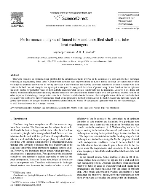
International Journal of Thermal Sciences46(2007)1311–1317/locate/ijtsPerformance analysis offinned tube and unbaffled shell-and-tubeheat exchangersJoydeep Barman,A.K.Ghoshal∗Department of Chemical Engineering,Indian Institute of Technology,Guwahati,North Guwahati781039,Assam,IndiaReceived15May2006;received in revised form26August2006;accepted6December2006Available online5February2007AbstractThis work considers an optimum design problem for the different constraints involved in the designing of a shell-and-tube heat exchanger consisting of longitudinallyfinned tubes.A Matlab simulation has been employed using the Kern’s method of design of extended surface heat exchanger to determine the behavior on varying the values of the constraints and studying the overall behavior of the heat exchanger with their variation for both cases of triangular and square pitch arrangements,along with the values of pressure drop.It was found out that an optimum fin height existed for particular values of shell and tube diameters when the heat transfer rate was the maximum.Moreover it was found out that the optimumfin height increased linearly with the increase in tube outer diameter.Further studies were also performed with the variation of other important heat exchanger design features and their effects were studied on the behavior of overall performance of the shell-and-tube heat exchanger.The results were thereby summarized which would proclaim to the best performance of the heat exchanger and therefore capable of giving a good idea to the designer about the dimensional characteristics to be used for designing of a particular shell and tube heat exchanger.©2007Elsevier Masson SAS.All rights reserved.Keywords:Fin height;Heat exchanger;Heat transfer rate;Longitudinalfins;Number of tube side passes;Pressure drop;Tube pitch layout1.IntroductionFins have long been recognized as effective means to aug-ment heat transfer.The literature on this subject is sizeable. Shell and tube heat exchanger with its tube eitherfinned or bare is extensively taught in the undergraduate level.Several text and reference books deal with the problems of longitudinalfinned tube in a shell and tube heat exchanger[1–4].It is well under-stood that with increase infin height of a longitudinalfin,heat transfer area increases to increase the heat transfer and at the same time the driving force decreases to decrease the heat trans-fer.However,one important design aspect,which probably is not discussed,is presented here.For a particular shell diameter, capacity of tube numbers is decided depending on tube size and pitch arrangement.In case offinned tube,height of thefin also plays an important role.Therefore,with increase infin height though surface area increases but number of tubes as well as *Corresponding author.E-mail addresses:joydeepb@iitg.ernet.in(J.Barman),aloke@iitg.ernet.in (A.K.Ghoshal).efficiency of thefin decreases.So,there might be an optimum condition of tube number andfin height for a particular tube arrangement and a particular shell diameter for which the heat transfer rate is the maximum[5].A Matlab coding has been de-signed to study the behavior of the overall performance of a heat exchanger on varying the important design features involved in it.The important constraints involved in the designing of a heat exchanger are studied here using the Matlab program.Several results and optimum conditions related to them are briefed out and tabulated in this literature to give a basic idea to the de-signer about the requirements and limitations to be included while designing afinned tube and unbaffled shell-and-tube heat exchanger.In the present article,Kern’s method of design[2]of ex-tended surface heat exchanger is applied for a shell-and-tube heat exchanger problem.Optimum conditions offin height and number of tubes in cases of triangular pitch and square pitch arrangements are found out along with the values of pressure drop.Other results concerning the various constraints of a heat exchanger like number of passes,tube outer diameter and tube pitch layout were also studied and compared in this literature.1290-0729/$–see front matter©2007Elsevier Masson SAS.All rights reserved. doi:10.1016/j.ijthermalsci.2006.12.0051312J.Barman,A.K.Ghoshal/International Journal of Thermal Sciences46(2007)1311–1317 Nomenclaturea s,a tfluidflow area.............................m2 A o,A i tube surface area...........................m2c s,c t specific heat capacity...............J kg−1K−1d thickness of eachfin.........................m de equivalent diameter for heat transfercalculations................................m D,D1inner and outer diameter of tube..............m D2inner diameter of shell.......................m D b tube bundle diameter........................m De s equivalent diameter for pressure dropcalculations................................m f s,f t friction factor offluidh f heat transfer coefficient offins......W m−2K−1 h f i heat transfer coefficient of outside tube surface andfins with respect to the inner tubesurface............................W m−2K−1 h i heat transfer coefficient of inside tubesurface............................W m−2K−1 H f height of eachfin...........................m G s,G t mass velocity offluid...............kg m−2s−1 K s,K t thermal conductivity...............W m−1K−1 L length of each tube..........................m n number of tube side passes N f number offins per tubeN T total number of tubesP t tube pitch..................................m P w wetted perimeter............................m Pr s,Pr t Prandtl numberQ overall heat transfer rate per unit LMTD..W K−1 Re s,Re t Reynolds numbers s,s t specific gravity offluidU overall heat transfer coefficient......W m−2K−1 w tube sidefluid’s massflow rate...........kg s−1 W shell sidefluid’s massflow rate...........kg s−1 P s, P t pressure drop............................Pa Greek symbolsμs,μt,μw viscosity..............................Pa s ηffin efficiencySubscriptsffini inside of tubeo outside of tubes shell sidet tube sidew wall2.The mathematical program model of Kern’s method and solution procedure:determination of tube bundle diameter and maximum number of tubesA shell-and-tube heat exchanger with an internal shell diam-eter,D2,consisting offinned tubes of outer diameter,D1,inner diameter,D,length,L,withfins of height,H f,and thickness, d,is considered here.Total number offins per tube is N f and total number of tubes is N T.Tube bundle diameter is D b:D b=(D1+2H f)×(N T/K)(1/M)(1) The constants,K and M,are determined from Table1for dif-ferent tube passes and tube pitch layouts for a tube pitch,P t=1.25(D1+2H f)[1](2) Tube bundle diameter isfirst calculated by iterative process for bare tubes;henceforth maximum number offinned tubes,N T,is calculated from the derived tube bundle diameter from Eq.(1).3.Shell side calculationsTheflow area,a s,wetted perimeter,P w,equivalent diame-ter,d e,mass velocity,G s,Reynold’s number,Re s and Prandtl number,Pr s are calculated using Eqs.(3)–(8)as follows:a s=πD22/4−N TπD21/4+N f×d×H f(3) P w=N T(πD1−N f×d+2N f×H f)(4) d e=4a s/P w(5) G s=W/a s(6) Re s=d e×G s/μs(7) Pr s=c s×μs/K s(8) The heat transfer coefficient for the outside tube andfin surfaces can be calculated using Sieder–Tate correlation[4],Eqs.(9)and(10)as shown below:h f=1.86(K s/d e)×(Re s×Pr s×d e/L)1/3(9) for laminarflow;Table1Values of constants,K and M[1]Triangular pitch Square pitchNo.of passes1246812468K0.3190.2490.1750.07430.03650.2150.1560.1580.04020.0331 M 2.142 2.207 2.285 2.499 2.675 2.207 2.291 2.263 2.617 2.643J.Barman,A.K.Ghoshal /International Journal of Thermal Sciences 46(2007)1311–13171313h f =0.027(K s /d e )×Re 0.8s ×Pr 1/3s×(μs /μw )0.14(10)for turbulent flow.4.Tube side calculationsThe tube side flow area,a t ,mass velocity,G t ,Reynolds number,Re t and Prandtl number,Pr t ,for tube side fluid are calculated from Eqs.(11)–(14).With the values of viscosity,μt ,specific heat capacity,c t and thermal conductivity,K t ,for tube side fluid and using the Sieder–Tate correlation,the heat transfer coefficient of inside tube surface,h i ,can be calculated.a t =πN T ×D 2 /4n (11)G t =w/a t (12)Re t =DG t /μt (13)Pr t =c t ×μt /K t(14)5.Fin efficiency calculationsThe process is assumed as a steady state one and there isa continuous flow of fluid in the axial direction (both in the shell and tube side).Therefore,for a particular value of radial location,the temperature for any location in the axial direction would be almost same.Further,the angular directional variation of temperature is also neglected.Thus,the problem is reduced to a one-dimensional heat conduction problem.Hence,the fin efficiency is represented as ηf and calculated using Eqs.(15)and (16).ηf =tanh (mH f )/(mH f )(15)wherem =(2h f /K f d)1/2(16)6.Heat transfer calculationsHeat transfer coefficient of outside surface and fins with respect to the inner surface of tubes,h f i and heat transfer coef-ficient of inside surface,h i ,are given as below using Eqs.(17),(21)and (22):h f i =(H f ×P ×N f ×ηf ×N T +A o )h f /A i(17)A o and A i are the outside bare tube surface area and inside surface area of tubes respectively,where P is the perimeter of a fin,as given by Eqs.(18)–(20).A o =(πD 1−N f d)×N T L (18)A i =πDN T L (19)P =2(L +d)(20)The heat transfer coefficient for the inside tube surface can be calculated using Sieder–Tate correlation [4],Eqs.(21)and (22)as shown below:h i =1.86(K t /D)×(Re t ×Pr t ×D/L)1/3(21)for laminar flow;h i =0.027(K t /D)×Re 0.8t ×Pr 1/3t×(μt /μw )0.14(22)for turbulent flow.Thus the overall heat transfer coefficient,U ,with respect to the inside tube surface is given by Eq.(23):U =(h f i ×h i )/(h f i +h i )(23)Finally,the heat transfer rate with respect to the inside tube sur-face area,Q per degree LMTD is calculated using Eq.(24)as follows:Q =U ×A i(24)7.Pressure drop calculationsEquivalent diameter for pressure drop calculations in case of shell side fluid will be different from the diameter used for heat transfer calculations.This diameter is given by Eq.(25):De s =4a s /(P w +πD 2)(25)The pressure drops for shell side and tube side fluid, P s and P t respectively are calculated using Eqs.(26)–(29)as follows:P s = f s ×G 2s ×L / 5.22×10¹⁰×De s ×s s (26)f s =16/Re s(27)for laminar flow andf s =0.0035+0.24/Re 0.42s(28)for turbulent flow.Here,Re s =(De s ×G s )/μsP t = f t ×G 2t×L ×n / 5.22×10¹⁰×D ×s t (29)where f t is the tube side friction factor and can be calculated as shown above,Eqs.(27)and (28),using tube side Reynolds number,Re t .s s and s t are the specific gravities of shell side and tube side fluids respectively [2].8.Solution basisAn exemplary problem discussed below is used to study the objectives as discussed.Hot fluid (3.8kg s −1)in shell-side is to be cooled by a cold fluid (6.4kg s −1)in tube side.Inner di-ameter of the shell and length of the shell are kept constant as 0.5and 4.88m respectively.Inner and outer diameters of the tube are varied.Number of fins with thickness 9×10⁻⁴m per tube is 20and is kept constant for all the calculations.Ther-mal conductivity of the fin material is 45W m −1K −1.Hot and cold fluids are oxygen gas and water respectively.The values for thermal conductivity,viscosity and heat capacity of oxygen gas and water are calculated at an average temperature of 353and 305K respectively.9.Results and discussionsThe Kern’s method of designing of shell and tube heat ex-changers with extended surfaces was used for the designing of the heat exchanger concerned in this paper.The equations in-volved in this method are all simple and well established,and1314J.Barman,A.K.Ghoshal /International Journal of Thermal Sciences 46(2007)1311–1317were incorporated in a Matlab program specially coded for the purpose of this paper.This program is simply a step-wise cal-culation and does not involve any iteration or any optimization technique that may lead to some numerical errors.However,the program was thoroughly checked and thereafter run to arrive at the reasonable conclusions as reported in the manuscript.The results tabulated in Tables 2–5,and results shown graph-ically in Figs.1and 2were found out for a tube outer diameter of 0.0254m.Tables 2and 3present the maximum number of finned tubes of different fin heights for triangular pitch and square pitch arrangements respectively,which can be accom-modated in the shell of inner diameter 0.5m.They also reflect the obvious nature of variations of the shell-side and tube-side pressure drops with variation of fin height keeping one tube pass only.It is well understood that as the number of tubes decreases with the increase in fin height,the tube side fluid flow area is decreased thereby increasing the pressure drop.On the other hand,the shell side flow area increases leading to decrease in pressure drop,which is also shown through Figs.1and 2for tri-angular pitch and square pitch arrangements respectively.The variations of the heat transfer rates for both the pitches with variations of fin height are reported in Tables 2and 3respec-Fig.1.Variation of heat transfer rate and shell-side pressure drop with increase in fin height for triangular pitch arrangement,one tube side pass and for tube outer diameter,0.0254m.tively.The nature of the variations is shown through Figs.1and 2for triangular pitch and square pitch arrangements respec-tively.It is observed from the figures that there exists an opti-mum fin height (0.4572×10⁻²m for triangular pitch and 0.4826×10⁻²m for square pitch arrangement),which gives the highest heat transfer rate.Corresponding to these optimum fin heights,optimum number of adjustable finned tubes is 78and 60respectively.Under these optimum conditions,heat transfer rates are 7798.4and 5843.0W K −1,tube side pressure drops are 0.2985and 0.4723kPa and shell side pressure drops are 1.3217and 0.8343kPa for triangular and square pitch arrange-ments respectively.Tables 4and 5show the corresponding values of optimum fin height,total number of tubes,heat transfer rate and pres-sure drop for different values of tube side passes.We notice from these tables (Tables 4and 5)that for a constant shell inner diameter,with increase in the number of tube-side pass the maximum heat transfer rate corresponding to the optimum value of fin height decreases.It is also noticed that as the total number of tubes decreases the tube side pressure drop values in-creases largely which is a major drawback from economicandFig.2.Variation of heat transfer rate and shell-side pressure drop with increase in fin height for square pitch arrangement,one tube side pass and for tube outer diameter,0.0254m.Table 2Capacity of finned tubes of 0.0254m outer diameter in the shell,pressure drops and heat transfer rate values for triangular pitch arrangement and for one tube side passHeight of fin,H f ×102,m 0.2540.3810.43180.45720.5080.55880.6350.762Total number of tubes,N T10286817873696355Shell side—pressure drop, P s ,kPa 1.4341 1.3692 1.3383 1.3217 1.2893 1.2569 1.2093 1.1335Tube side—pressure drop, P t ,kPa0.18820.2530.28270.29850.3330.36950.42950.546Heat transfer rate per unit LMTD,Q ,W K −17469.37767.17797.37798.47777.47730.57622.47371.2Table 3Capacity of finned tubes of 0.0254m outer diameter in the shell,pressure drops and heat transfer rate values for square pitch arrangement and for one tube side pass Height of fin,H f ×102,m 0.2540.3810.40640.43180.45720.48260.5080.5334Total number of tubes,N T8268666462605850Shell side—pressure drop, P s ,kPa 0.87630.86050.85430.8480.84110.83430.82740.8191Tube side—pressure drop, P t ,kPa0.27650.37570.39850.4220.44610.47230.49850.5268Heat transfer rate per unit LMTD,Q ,W K −15522.45797.55820.45835.15842.45843.05837.65826.8J.Barman,A.K.Ghoshal /International Journal of Thermal Sciences 46(2007)1311–13171315optimization point of views.As expected,the shell side pressure drop decreases with decrease in tube number but the decrease is much less in comparison to the increase for the tube side pressure drop.So,in this case,the tube side pressure drop val-ues bear more importance while selecting the number of passes.Hence,from the tabulated data obtained it can be said that one tube side pass is the best choice for the finest results of heat ex-changer performance unless a constraint related to the number of tubes is faced when higher values of tube side pass could be considered.Moreover,it was also noticed that for a particular fin height,the total number of adjustable tubes varies for the pitch arrangements.As the number of tubes that could be ad-justed in a square pitch arrangement were less in number than in triangular pitch arrangement so even the most optimum value of fin height in case of square pitch arrangement could not pro-duce the same heat transfer rate as compared to the other.But the shell side pressure drop is higher in magnitude in triangu-lar pitch than in square pitch arrangement,whereas the relation is just the opposite in case of tube side pressure drop values.So,in the absence of any pressure drop constraints,thetriangu-Fig.3.Variation of optimum fin height with outer diameter of tubes.lar pitch arrangement with the optimum value of fin height will prove to be the best choice.The other tables,i.e.,Tables 6–9give the values of different important parameters such as a s ,A i ,A o ,Re s ,Pr s ,h f ,ηf ,h f i ,h i and U used and determined during the calculations.Fig.3shows the variation of optimum fin height with the change of tube outer diameters for a fixed number of tube side passes and for triangular pitch arrangement.The relation between them is found to be linear and can be expressed by Eq.(30):H f =0.0852×D 1+0.0025(30)Thus by using this equation,an approximate value of optimum fin height for the highest heat transfer rate can be pre-calculated for a tube of particular diameter.Fig.4shows a comparison of the performance of the heat exchanger for one and two tube side passes for triangular pitch arrangement.It is found out that the performance of the heat exchanger based on the heat transfer rate values for two-tube side passes could never meet up with the results for one tube side pass.Also after inspecting thepres-parison of heat transfer rates with fin heights for one and two tubes side passes.Table 4Optimum fin height for maximum heat transfer rate,for different tube-side passes and corresponding values of total number of finned tubes and pressure drops for triangular pitch arrangement and for tube outer diameter as 0.0254m Number of tube side passes,n 12468Optimum fin height,H f ×102,m0.45720.45720.45720.43180.38Heat transfer rate per unit LMTD,Q ,W K −17798.47639.46523.84383.53166.4Total number of finned tubes,N T 7872624740Shell-side pressure drop, P s ,kPa 1.3217 1.12040.84170.50830.3567Tube-side pressure drop, P t ,kPa0.29852.29120.032298.8108297.322Table 5Optimum fin height for maximum heat transfer rate,for different tube-side passes and corresponding values of total number of finned tubes and pressure drops for square pitch arrangement and for tube outer diameter as 0.0254m Number of tube side passes,n 12468Optimum fin height,H f ×102,m0.48260.45720.48260.40640.4064Heat transfer rate per deg.LMTD,Q ,W K −158435476.75286.92911.72503.0Total number of finned tubes,N T 6056513632Shell-side pressure drop, P s ,kPa 0.8340.70310.63640.32520.2773Tube-side pressure drop, P t ,kPa0.47233.557827.9617160.236441.3241316J.Barman,A.K.Ghoshal/International Journal of Thermal Sciences46(2007)1311–1317Table6Values of various parameters involved in determining the important variables of Table2Height offin,H f×102,m0.2540.3810.43180.45720.5080.55880.6350.762 Shell sideflow area,a s,m2 1.41 1.485 1.511 1.523 1.546 1.567 1.596 1.637 Inside tube surface area,A i,m231.326.3724.7123.9422.521.1819.4116.9 Outside tube surface area,A o,m231.10126.2124.5623.79322.3621.0519.2816.8 Shell side 3.988 3.612 3.521 3.483 3.423 3.377 3.33 3.294 Reynolds number,Re s×10−4Shell side0.7010.7010.7010.7000.7010.7010.7010.701 Prandtl number,Pr sFin heat transfer111.8108.26106.96106.34105.14104.01102.42100.05 coefficient,h f,W m−2K−1Fin efficiency,ηf0.98820.97460.9680.96450.95710.94920.93640.9133 Heat transfer coefficient of291.03365.342392.96406.34432.25457.06492.27545.82fins and outside tube surfacewith respect toinside tube surface,h f i,W m−2K−1Inside tube surface heat 1.325 1.52 1.601 1.642 1.726 1.811 1.943 2.17 transfer coefficient,h i×10−3,W m−2K−1Overall heat transfer coefficient238.63294.55315.52325.75345.68364.97392.74436.11 with respect toinside tube surface,U,W m−2K−1Table7Values of various parameters involved in determining the important variables of Table3Height offin,H f×102,m0.2540.3810.40640.43180.45720.48260.5080.5334 Shell sideflow area,a s,m2 1.532 1.595 1.606 1.6162 1.626 1.636 1.645 1.654 Inside tube surface area,A i,m225.0320.9820.28319.6218.9818.3817.8117.26 Outside tube surface area,A o,m224.8820.8520.15719.518.8718.2717.717.16 Shell side 4.987 4.54 4.484 4.434 4.392 4.355 4.323 4.296 Reynolds number,Re s×10−4Shell side0.7010.7010.7010.7010.7010.7010.7010.701 Prandtl number,P r sFin heat transfer98.3796.3295.9195.595.0994.794.393.92 coefficient,h f,W m−2K−1Fin efficiency,ηf0.98960.97730.97440.97130.96810.9650.96130.9577 Heat transfer coefficient of256.3325.67338.81351.72364.38376.81389.0400.96fins and outside tube surface withrespect to insidetube surface,h f i,W m−2K−1Inside tube surface heat 1.585 1.825 1.875 1.926 1.977 2.028 2.081 2.133 transfer coefficient,h i×10−3,W m−2K−1Overall heat transfer coefficient220.62276.36286.96297.4307.67317.78327.73337.52 with respect toinside tube surface,U,W m−2K−1sure drop values(Table4),it can be well concluded that the best option would be to select a heat exchanger with one tube side pass if there is no tube number constraint involved.Hence it can be well summarized by mentioning that a combination of triangular pitch arrangement,one tube side pass and a value of fin height calculated from Eq.(30),when incorporated in the designing of a shell-and-tube heat exchanger with no baffles would certainly proclaim to give the best performance until and unless some restriction is being levied on in terms of pressure drop or number of tubes.10.ConclusionsIn this work the variation of heat transfer rate withfin height for afinned tube shell-and-tube heat exchanger was studied for two different pitch arrangements.It was found out that for par-J.Barman,A.K.Ghoshal/International Journal of Thermal Sciences46(2007)1311–13171317 Table8Values of various parameters involved in determining the optimumfin height and other important variables of Table4Number of tube side passes,n12468 Optimumfin height,H f×102,m0.45720.45720.45720.43180.38 Shell sideflow area,a s,m2 1.523 1.5619 1.6261 1.722 1.7725 Inside tube surface area,A i,m223.9422.0818.9914.512.238 Outside tube surface area,A o,m223.79321.9418.87514.4112.163 Shell side Reynolds number,Re s×10−4 3.483 3.778 4.391 6.0017.798 Fin heat transfer coefficient,h f,W m−2K−1106.34102.0495.184.3777.781 Fin efficiency,ηf0.96450.96590.96810.97460.9817 Heat transfer coefficient offins and outside406.34390.3364.4311.5263.33 tube surface with respect to inside tubesurface,h f i,W m−2K−1Inside tube surface heat transfer coefficient, 1.642 3.051 5.992 1.0285 1.4827 h i×10−3,W m−2K−1Overall heat transfer coefficient with respect325.75346.03343.51302.34258.74 to inside tube surface,U,W m−2K−1Table9Values of various parameters involved in determining the optimumfin height and other important variables of Table5Number of tube side passes,n12468 Optimumfin height,H f×102,m0.48260.45720.48260.40640.4064 Shell sideflow area,a s,m2 1.636 1.6644 1.692 1.795 1.8206 Inside tube surface area,A i,m218.3817.1515.7111.0379.788 Outside tube surface area,A o,m218.2717.0515.61310.979.728 Shell side Reynolds number,Re s×10−4 4.355 4.826 5.0978.249.291 Fin heat transfer coefficient,h f,W m−2K−194.791.0488.7275.9673.118 Fin efficiency,ηf0.9650.96940.9670.97960.9803 Heat transfer coefficient offins and outside376.81349.19353.61269.38259.44 tube surface with respect to inside tubesurface,h f i,W m−2K−1Inside tube surface heat transfer coefficient, 2.028 3.734 6.974 1.28 1.773 h i×10−3,W m−2K−1Overall heat transfer coefficient with respect317.78319.3336.54263.82255.69 to inside tube surface,U,W m−2K−1ticular shell and tube diameters an optimum value offin height exists,which gives the highest heat transfer rate.Moreover it was also found out that on increasing the number of tube side passes while keeping the shell diameter constant,though the number of tubes could be decreased but the performance on the basis of heat transfer rate kept on decreasing and tube side pressure drop values increased substantially.The optimumfin height also increased linearly with the increase of tube outer diameter.It is worth mentioning here that the Matlab coding designed for this problem and the results obtained on using it,might prove quite beneficial in choosing the most appropriatefin height,total number of tubes,tube dimensions,arrangements, number of tube side passes andfin dimensions for a known value of shell diameter as well as keeping the pressure drops in check.In this problem the physical properties of thefluids were assumed constant,tube andfin dimensions were assumed uniform,throughout the entire system.It can be further stated that no experimental verification could be possible due to lack of such experimental data.How-ever,it would be highly appreciated to carry experimental work in this regard.References[1]J.R.Backhurst,J.M.Coulson,J.H.Harkar,J.F.Richardson,Coulson&Richardson’s Chemical Engineering,Butterworth–Heinemann,Oxford, 2004.[2]D.Q.Kern,Process Heat Transfer,McGraw-Hill,New York,2000.[3]P.Harriott,W.L.McCabe,J.C.Smith,Unit Operations of Chemical Engi-neering,McGraw-Hill,New York,2001.[4]S.P.Dusan,R.K.Shah,Fundamentals of Heat Exchanger Design,John Wi-ley and Sons,New York,2003.[5]J.Barman,A.K.Ghoshal,in:Proceedings of Chemcon’05,58th AnnualChemical Engineering Congress,India,2005.。
换热站自动控制系统设计外文文献+翻译
外文文献:Design and Implementation of Heat Exchange Station Control SystemKeywords:Heat exchange station, Control system, PLC, Inverter, Configuration software.Abstract.This paper introduces a design and implementation of heat exchange station control systembased on PLC and industrial configuration software, which includes the contr ol scheme and principle,hardware selection and software design, etc. The circulating pumps and re plenishing pumps in thesystem can all be driven automatically by PLC and inverter. Main process parameters, such as steampressure and measurement temperature and so on,can all be shown on the industrial PC runningconfiguration software, and instructions could be sent by the engineer and operator on-the-spot via theHuman Machine Interface as well. The automatic pressures adjustment of stea m supply of the heaterby advanced PID algorithm has been realized finally. It is verified that the system is highly reliableand stable, and it greatly enhances the level of automation and pressure control accuracy of the heatexchange station and meets all the equipments running demands well. IntroductionWith the rapid development of economy and society, heat supply systems are the key power source inthe communities and plants in China. As a media between heat sources and heat loads in the systems,a heat exchange stations plays a very important role for the heat supplyquality. Traditionally, most ofthe pumps in the heat supply systems are operated by valves manually, s o it could bring about thepower energy consuming, high labor intensity and low operation automation. I n this paper a design ofcontrol system for heat exchange station based on PLC, inverter and indust rial configuration softwarewas proposed,accordingly the aim for power energy saving,high heat efficiency and operationautomation has been achieved.Process outline and Control demandsProcess outline.The process outline and control demands were put forward at first before the schemeand design of heat exchange station control system were proposed.Heat exchange station consists of a steam-driven heater,plus3ci rculating pumps,2replenishingpumps and electric control valve. By adjusting the steam flux into the mixture of water and steamaccording to the temperature sensors mounted indoors and outdoors, the pr ocess of heat exchangecould be completed. Among these equipments, the steam-driven heater, a heat exchanger containingmixture of steam-and-water, is the key appliance for heat supply system.Control demands.Major control demands for the control system were listed a s follows [1]:(a)Pumps driving.Pumps include3circulating pumps(2in operation,1for backup)and2replenishing pumps (1 in operation, 1 for backup). Among circulating ones one is driven by powerfrequency, the others are driven by variable frequency, with 75KW power ea ch; among replenishingones one is driven by power frequency, the other is driven by variable frequency, with 3KW powereach. The control signal should be originated from the pressure difference between the supply waterand return water.Pumps could be driven in stepless speed regulating when connecting variablepower;(b)Parameters Showing.The showing parameters contain temperatureshowing-temperature ofsupply water, return water, the indoor, the outdoor and steam - and pre ssure showing - pressure ofsupply water, return water and pre-valve and post-valve of the steam etc;(c) Butterfly valves driving.Two butterfly valves can be on or of f automatically when the wholesystem start or stop;(d) Motor-driven valves control. By continuously adjusting the opening of t he valves according to thesignal from the temperature sensors indoors and outdoors, the supply wate r temperature should bestabilized in the presetting values;(e) HMI (Human Machine Interface) Demands. The process flow chart of heatexchange station andmain process parameter can be shown in HMI, and instructions can be trans mitted via this interface;(f) Safeguard Function. The circulating pumps should be out of running when heat exchange system isin water needing, and steam should be kept out of the heater when the pumps are not revolving.Hardware Selection of the Control SystemFrom the control demands mentioned above, the controller of the control s ystem can process signalsboth relay and analog, having the ability of loop adjustment of analog q uantity. At the meantime thepumps could run in the working condition of variable frequency, so the hardware selection of thecontrol system for heat exchange station should be made deliberately.PLC Serving as Main Controller.As some experienced electrica l engineers known,PLC/PC(Program Controller) is a kind of popular industrial computer, and it can not only accomplish logiccontrol, but also complete many advanced functions, such as analog quanti ty loop adjustment, andmotion control, etc. According to the component amounts of input and outpu t and the needs of controlsystem, FX1N-60MR micro PLC of MITSUBISHI FX series is selected, which hav ing 36 inputs and24 outputs, and doing analog adjustment by using advanced instruction likePID instruction [2].Because of the sampling and driving of the analog signal necessarily, P LC should be extended toanalog input/output function module like FX2N-4AD (4AD) and FX2N-4DA (4DA) or somethinglike.On one hand,4AD adopted is an analog input module having4channels with12bit highresolution, which could receive 0~+10V voltage signal, 0~20mA or 4~20mA cu rrent signal. On theother hand, 4DA chosen could send standard voltage signal and/or current signal, having 4 channelswith 12 bit high resolution also. It is something to be mentioned here , the wiring form of currentinput/output (4~20mA) must be adopted in order to avoiding the strong elec tromagnetism disturbancein the working field [3].Inverter completing Stepless Speed Regulating.At present, inverter, as an im port power electronicconverter, can convert constantly power frequency into continually variable frequency. Thus, energysaving, cost consuming and noise reduction can be easily reached by this equipment.In this control system inverter of ACS510 series of ABB Corporation were elaborately chosen, whichhas many advantages, such as Direct Torque Control (DTC) and advanced appl ying macro and so on.Its main good points and characteristics are illustrated as follows: it can acquire maximum startingtorque (200% normal torque) by using direct excitation; it can be applied to multiple driving systemsby using master-slave function;input and output programmable function;high precision of speedregulating, perfect safeguard and alarming steps. Owing to these highlights of this inverter, pumpsdriving of stepless speed regulating can be easily obtained.There are many applying macro inACS510 series, but we should only choose manual/automatic macro here as we need.IPC Acting as Monitor&Control Interface.IPC(Industrial Personal Computer)has strongcompatibility,extensibility and reliability,which can connect PLC by RS-232serial portconveniently. In the hardware configuration we select IPC H610 series of A DVANTECH as HMI.MCGS(Monitor Control Generated System),fashionable home-mad e industrial configurationsoftware, is running on the ADVANTECH IPC. Using this HMI, the visualizati on process of Monitorand Control is realized easily, intuitively and vividly.With the sensor/transducer,analog input/output modules,PLC a nd actuators,.inverter andmotor-driven valve, the loop adjustment of steam pressure can be precisely attained, and temperatureof all measure points could be measured also[4].The overall hardware configuration of heatexchange station control system see Fig. 1.Fig. 1 The overall hardware configuration of heat exchange station control systemSoftware Design of the Control SystemLAD Diagram Programming.Out of the thoughts of modular programming, the whole programstructure can be divided into such several modules as Initialization Function,upper IPCCommunication Function, Relay Control Function, Analog Sampling, Fuzzy PID Adjust Functionand Safeguard Function, etc. The flow chart of LAD diagram programming of PLC is shown in Fig. 2.Among these modular functions, it is something worthy to mention of Fuzzy PID Adjust Function.Under some circumstances the using of PID instruction of PLC was not so good at what we expected;therefore, the self-made program of Fuzzy PID adjustment of steam pressure was done from deviationand deviation acceleration of temperature between the indoor and the outdoo r in accordance with theFuzzy Control Theory and its application [5].HMI Configuration.For the sake of the appearance beauty and personalizati on between machineand human, the MCGS- Monitor Control Generated Software of Beijing MCGS Tech Co. Ltd wasadopted. This industrial configuration software has very quick, easy devel opment of configurationprocess, which can build bi-directional and high speed communication betwee n PLC and upper IPCthru RS422/232 serial port.In the development environment of MCGS, all needed windows and pictures we re created, includingMain Window of Process Flow, Process Parameters Showing Window, and Key P arameters SettingWindow, etc. Vivid and readily interaction between human and machine can be completed by suchbeautiful pictures and animations when IPC running MCGS.ConclusionsThis design of heat exchange station control system based onFX series PLC,MCGS,and ABBinverter has been realized the pressure automatic adjustment of steam-driven heater as originallyexpected.More over,design demands of power energy savi ng,high heat efficiency and lowequipments noise can all be well met. Finally, the practical operation ver ifies that the system is highlyreliable and stable, and it greatly enhances the level of automation and pressure control accuracy ofheat exchange station and meets equipments requirements of energy saving an d green driving.BEGINInitializationFuzzy PIDAdjust FunctionCommunicationFunctionAnalog OutputNoRelay ControlFunctionAnalog FilteringFunctionCall AnalogSample FunctionSample OverYesAnalog InputLinear TransferLinear TransferAnalog OutputDrivingSafeguard FunctionFailure OccurNoYesFailure HandlingRelated MemoryResetENDFig. 2 The flow chat of LAD diagram programming of PLCAcknowledgementComposition of this paper was with the help and under the direction ofSenior Engineer Nian-huiZhang of Qingdao Wellborn Automation Corporation.References[1]Information on H. Zhang, . Li:The Principle of PLC with itsApplications to Process Control(China PowerPress, Beijing 2008).[3]H. Zhang:The Design and Development of MITSUBISHI FX Series PLC( China Machine Press,Beijing 2009).[4]H. Zhang: Process Automation Instrumentation, Vol. 31(4) (2010), p. 34-36, in Chinese.[5]. Zadeh:Fuzzy Sets and their Applications(Academic Press, New Yor k 1975).Progress in Civil Engineeringand Implementation of Heat Exchange Station Control System外文翻译:换热站控制系统的设计和实现关键词:换热站、控制系统、PLC、变频器、配置软件。
不锈钢制换热器的优化设计文献翻译

One of the most effective methods of increasing the rate of heat transfer in heat exchangersis using tubes with lengthwise corrugations (Fig. i). Among the different methodsknown here and abroadfor making such tubes (longitudinal and rotary rolling, welding, drawing,forging), cold drawing occupies an important position. This is because of the highproductivity of this method, the accuracy of the tube dimensions, the good surface finish,and the fact that the tool is relatively simple to fabricate. A technology has been developedand introduced at several nonferrous metallurgical plants for drawing copper-alloy tubeswith lengthwise corrugations.The Pervouralsk New Tube Plant is developing a technology for drawing such tubes madeof carbon steel. Trial lots of tubes with a corrugated outer surface have been made andstudies are being conducted to determine the optimum geometry of the die.There are certain distinctive features of drawing stainless steel tubes that owe to theproperties of the material. The cold working of alloy steels -- thus, stainless steels -- ischaracterized by a high susceptibility to work hardening, low thermal conductivity, and thepresence of a hard and strong film on the surface which is passive to lubricants. The presenceof the film leads to seizing of the tube in the die. Existing lubricants and prelubricantcoatings do not provide a plasticized layer that will prevent the metal from adheringto the die and ensure a uniform strain distribution over the tube wall thickness.The Ural Polytechnic Institute and the Institute of Electrochemistry of the Ural ScienceCenter under the Academy of Science of the USSR have developed a technology for applying acopper coating to the surface of tubes made of corrosion-resistant steels. The coating isapplied in the form of a melt containing copper salts at 400-500~ and allowed to stand fori0 min. The layer of copper 10-40 ~m thick formed on the surface by this operation is stronglybound to the base metal. The copper coating makes it possible to draw tubes of stainlesssteel on a mandrel.The sector metallurgical-equipment laboratory at the UralPolytechnic Institute studiedthe process of drawing stainless steel tubes using the copper coating on short(stationary)and long (movable) mandrels. The study showed that the metal does not adhere to the die, thecoating is strongly bound to the base metal, and large reductions can be made in one pass.These results suggested that stainless-steel tubes with lengthwise corrugations could beproduced by cold drawing. Thus, the laboratory prepared trial lots of corrugated steel12KhI8NIOT tubes.其中一个最有效的办法来增加率换热器的传热利用管corrugations与纵向(Fig.我)。
换热器文献综述

管壳式换热器强化传热研究摘要:从管程强化和壳程强化两方面论述了管壳式换热器强化传热技术的机理,指出了管壳式换热器今后发展中的主要方向;同时对换热器的防腐措施以及改进动向作了介绍。
关键词:强化传热;管壳式换热器;防腐Abstract: shell and tube heat exchanger was discussed from two aspects of the strengthening of the tube side and the strengthening of the shell to strengthen the mechanism of heat transfer technology, pointing out that the main direction of future development of the shell and tube heat exchanger; heat exchanger anti-corrosion measures well as improved trends were introduced. Keywords: heat transfer enhancement; shell and tube heat exchanger; anti-corrosion引言管壳式换热器是当今应用最广泛的换热设备,它具有高的可靠性和简单易用性。
特别是在较高参数的工况条件下,管壳式更显示了其独有的长处“目前在提高该类换热器性能所开展的研究主要是强化传热,适应高参数和各类有腐蚀介质的耐腐材料以及为大型化的发展所作的结构改进。
一、换热器的强化传热研究换热器的强化传热就是采用一定的措施增大换热设备的传热速率,力图用较少的传热面积或体积的设备来完成传热任务。
各种强化型换热器在石油、化工、制冷、航空、车辆、动力机械等工业部门己得到广泛应用。
强化传热已被学术界称为第二代传热技术。
(译文)换热器英文参考文献
应用计算数值的方法来研究流体的粘度变化对板式换热器性能的影响M.A. Mehrabian and M. KhoramabadiDepartment of Mechanical Engineering, Shahid Bahonar University of Kerman,Kerman, Iran摘要目的--本文的目的是在逆流和稳态条件下,通过数值计算,研究流体粘度的变化对板式换热器热特性的影响。
设计/工艺/方法--实现这篇文章目的的方法,源于由4部分组成的热量交换板中间通道中冷热流体的一维能量平衡方程。
有限差分法已经用于计算温度分布及换热器的热性能。
在侧边通道中,水作为将被冷却的热流体,然而在中央通道中,大量随温度变化同时粘度随之变化剧烈的流体作为将要被加热的冷流体。
发现—这个程序的运行实现了工作流体的结合,例如水与水,水与异辛烷,水与苯,水与甘油和水与汽油等。
对于以上所有工作流体的结合,两种流体的温度分布已经沿流动通道划分。
总传热系数可以通过冷流体和热流体的温度来绘制。
研究发现,若总传热系数呈线性变化,在温度变化范围内既不是冷流体和热流体的温度。
当粘度已受温度影响或者冷流体的性质改变时,换热器的影响效果并不是很显著。
创意/价值--对于由2块板为边界的温度控制体来说,本文包含一个可以得到能量平衡方程数值解的新方法。
通过对数值计算结果与实验结果进行比较,验证了这种数值计算方法。
关键词:热交换器、热传递、数值分析、有限差分法研究类型:研究性论文。
术 语2:m A 板传热面积,m b 板间距,:等式常数:CC ︒W/:C 热容,C kg J C p ︒⋅/:定压比热容,m D e 当量直径,:Cm W h ︒⋅2/:对流传热系数, 指定轴截面:jC m W k ︒⋅/:板传导率,m L 板长度,:粘度修正系数:ms kg m /:质量流量,•之间的斜率与e r R NuP n 31:-NTU: 传热单元数Nu: 努塞尔数Pr: 普朗特数Q: 传热速率, WRe: 雷诺数r: 方程指数 (8)t: 时间, sT: 温度, ℃u: 流速, m/sC m W U ︒⋅2/:总传热系数,C m W U ︒-⋅2/:平均传热系数,3:m V 通道体积,w: 流动宽度, mx: 横向坐标y: 轴向坐标sm kg m ⋅/:流体动粘度系数, 3/:m kg r 流体密度,l: 换热器有效性d: 板厚度, mf: 板投影面积的比值下标c : 冷流体Cv: 控制体h : 热流体m : 平均值min:最小值w : 板壁介绍板式换热器在不同产业发展进程中的贡献日益增加。
- 1、下载文档前请自行甄别文档内容的完整性,平台不提供额外的编辑、内容补充、找答案等附加服务。
- 2、"仅部分预览"的文档,不可在线预览部分如存在完整性等问题,可反馈申请退款(可完整预览的文档不适用该条件!)。
- 3、如文档侵犯您的权益,请联系客服反馈,我们会尽快为您处理(人工客服工作时间:9:00-18:30)。
Abቤተ መጻሕፍቲ ባይዱtract
In this part of the paper, the performance of the simultaneous charging/discharging operation modes of the heat pipe heat exchanger with latent heat storage is experimentally studied. The experimental results show that the device may operate under either the fluid to fluid heat transfer with charging heat to the phase change material (PCM) or the fluid to fluid heat transfer with discharging heat from the PCM modes according to the initial temperature of the PCM. The melting/solidification curves, the performances of the heat pipes and the device, the influences of the inlet temperature and the mass flow rate of the cold water on the operation performance are investigated by extensive experiments. The experimental results also disclose that under the simultaneous charging/discharging operation mode, although the heat transfer from the hot water directly to the cold water may vary, it always takes up a major part of the total heat recovered by the cold water due to the very small thermal resistance compared with the thermal resistance of the PCM side. The melting/solidification processes taking place in the simultaneous charging/discharging operation are compared with those in the charging only and discharging only processes. By applying a simplified thermal resistance analysis, a criterion for predicting the exact operation modes was derived and used to explain the observed experimental phenomena. Ó 2005 Elsevier Ltd. All rights reserved.
968
Z. Liu et al. / Energy Conversion and Management 47 (2006) 967–991
Keywords: Latent heat storage; Heat pipe; Heat exchanger; Heat transfer; Experimental
The thermal resistances from the hot water to the cold water via the heat pipes in our unit are: the forced convection heat transfer resistance Rhh between the hot water and the heat pipe wall, the thermal conduction resistance Rw of the heat pipe wall, the thermal resistance Rfh between the inner wall surface and the working fluid of the part of the heat pipe that is in the hot water passage, the axial thermal resistance RHP of the heat pipe, the thermal resistance Rfc between the inner wall surface and the working fluid of the part of the heat pipe that is in the cold water passage, the thermal conduction resistance Rw of the heat pipe wall and the forced convection heat transfer resistance Rhc between the cold water and the heat pipe wall. The thermal resistances from the PCM to the heat pipe are: the PCM equivalent thermal resistance RPCM, the thermal conduction
1. Introduction
In the first part of this paper, a new design of heat pipe heat exchanger with latent heat storage that resulted from a critical study of the published literature was presented. The new latent heat thermal storage system has many advantages over conventional approaches. The heat transfer surfaces for the different heat transfer processes of the heat pipe heat exchanger with latent heat storage can be designed independently, which permits arranging more heat transfer area for the phase change material (PCM) side that is usually the largest thermal resistance. Furthermore, the system has multiple operation modes. It can operate in the charging only, discharging only and simultaneous charging/discharging modes. In the first part of this paper, our experimental work showed that the new device performs the designed functions very well. It can both store and release the thermal energy efficiently. Therefore, the device can be used as a conventional system in which the charging and discharging are operated independently. In this part of the paper, we will report the experimental results for the simultaneous charging/discharging mode. As has been discussed in the first part of this paper, the simultaneous charging/discharging mode can actually be further classified into a fluid to fluid heat transfer process with charging heat to the PCM and/or a fluid to fluid heat transfer process with discharging heat from the PCM, which are the main topics of the present part of the paper.
Energy Conversion and Management 47 (2006) 967–991 /locate/enconman
An experimental study on the heat transfer characteristics of a heat pipe heat exchanger with latent heat storage. Part II: Simultaneous charging/discharging modes