AN4326-ieee1588
RCS-9613C线路光纤纵差保护装置技术和使用说明书

RCS-9613C线路光纤纵差保护装置技术和使用说明书南瑞继保电气有限公司版权所有本说明书适用于RCS-9613C系列V2.1* 和 V2.2*版本程序。
本说明书和产品今后可能会有小的改动,请注意核对实际产品与说明书的版本是否相符。
更多产品信息,请访问互联网:。
目录1 概述 (1)1.1 应用范围 (1)1.2 保护配置和功能 (1)1.2.1 保护配置 (1)1.2.2 测控功能 (1)1.2.3 保护信息功能 (1)1.3 性能特征 (1)1.4装置执行标准 (2)2 技术参数 (2)2.1 机械及环境参数 (2)2.1.1 机箱结构尺寸 (2)2.1.2 工作环境 (2)2.1.3 机械性能 (2)2.2 额定电气参数 (2)2.2.1 额定数据 (2)2.2.2 功耗 (3)2.3.1 光纤纵差保护 (3)2.3.2 过流保护 (3)2.3.3 零序保护 (3)2.3.4 低周保护 (3)2.3.5 重合闸保护 (3)2.3.6 遥信开入 (3)2.3.7 遥测量计量等级 (3)2.3.8 电磁兼容 (4)2.3.9 绝缘试验 (4)2.3.10 输出接点容量 (4)3 软件工作原理 (4)3.1 光纤纵差保护 (4)3.2 过流保护 (5)3.3 零序保护(接地保护) (5)3.4 过负荷保护 (6)3.5 加速保护 (6)3.6 低周保护 (6)3.7 重合闸 (6)3.8 装置自检 (6)3.9 装置运行告警 (6)3.10 遥控、遥测、遥信功能 (6)3.11 对时功能 (7)3.12逻辑框图 (7)4 硬件原理说明 (8)4.1装置整体结构 (8)4.2 装置面板布置 (9)4.3 装置接线端子与说明 (9)4.3.2 背板接线说明 (11)4.3.3 跳线说明 (12)4.4 结构与安装 (13)4.4.1 开关柜安装参考尺寸 (13)4.4.2 组屏安装参考尺寸 (14)5 定值内容及整定说明 (15)5.1 系统定值 (15)5.2 保护定值 (16)5.3 通讯参数 (17)5.4 辅助参数 (18)6 使用说明 (19)6.1 液晶显示说明 (19)6.1.1主画面液晶显示说明 (19)6.1.2 保护动作时液晶显示说明 (20)6.1.3运行异常时液晶显示说明 (20)6.1.4 自检出错时液晶显示说明 (20)6.2 命令菜单使用说明 (20)6.2.1 装置整定 (22)6.2.2 状态显示 (22)6.2.3 报告打印 (22)6.2.4 时间设置 (22)6.2.5 报告显示 (22)6.2.6 报告清除 (22)6.2.7 装置测试 (22)6.2.8 版本信息 (23)6.3 指示灯说明 (24)6.4 装置的运行说明 (24)6.4.1 装置正常运行状态 (24)6.4.2 装置异常信息含义及处理建议 (24)6.4.3 安装注意事项 (24)6.5 事故分析注意事项 (25)7 装置调试大纲 (25)7.1 试验注意事项 (25)7.2 事故分析注意事项 (25)7.3 交流回路检查 (26)7.4 输入接点检查 (26)7.5 整组试验 (26)7.5.1 光纤电流差动保护 (26)7.5.2 过流Ⅰ段保护 (27)7.5.3 过流Ⅱ段保护 (27)7.5.4 过流Ⅲ段保护 (28)7.5.5 零序Ⅰ段保护 (28)7.5.6 零序Ⅱ段保护 (28)7.5.8 重合闸保护 (28)7.5.9 过流加速保护 (28)7.5.10 零序加速保护 (28)7.5.11 过负荷保护 (28)7.5.12 低周保护 (29)7.6 运行异常报警试验 (29)7.6.1 频率异常报警 (29)7.6.2 接地报警 (29)7.6.3 PT断线报警 (29)7.6.4 控制回路断线报警 (29)7.6.5 TWJ异常报警 (29)7.6.6 CT断线报警 (29)7.6.7 差流报警 (29)7.6.8 通道故障 (29)7.6.9 弹簧未储能报警 (30)7.7 装置闭锁试验 (30)7.8 输出接点检查 (30)7.9 装置试验菜单的说明 (30)7.10 装置与监控后台联调的说明 (30)7.10.1 遥控功能的说明 (30)7.10.2 遥测值系数的说明 (31)7.10.3 装置与后台进行通讯联调时信息文本的说明 (31)8 附录 (31)8.1 插件选配方式1(YL方式) (31)8.1.1 YL方式选配插件硬件图 (32)8.1.2 YL方式选配插件背板端子图 (33)8.1.3 YL方式选配插件背板端子说明 (33)8.2 插件选配方式2(CK方式) (35)8.2.1 CK方式选配插件硬件图 (35)8.2.2 CK方式选配插件背板端子图 (36)8.2.3 CK方式选配插件背板端子说明 (36)8.3 软件配合说明 (37)8.4 SWI插件板号说明 (37)8.5 插件命名对照表 (37)NARI-RELAYS RCS-9613C线路光纤纵差保护装置RCS-9613C线路光纤纵差保护装置技术和使用说明书1 概述1.1 应用范围RCS-9613C适用于110kV以下电压等级的非直接接地系统或小电阻接地系统中的线路光纤纵差保护、电流保护以及测控装置,可组屏安装,也可在开关柜就地安装。
具有13V过压保护的USB电源管理与锂离子,聚合物电池充电器

具有13V过压保护的USB电源管理与锂离子,聚合物电池
充电器
佚名
【期刊名称】《电子元器件应用》
【年(卷),期】2007(9)8
【摘要】Linear Technology日前推出单片线性电源管理器、理想二极管控制器和独立电池充电器LTC4067.该器件适用于便携式产品和电池备份系统。
LTC4067可以接受USB电源、交流适配器或电池电源。
它具有PowerPathTM控制功能,可向外部设备供电,也可U.USB总线或交流适配器电源给单节锂离子/聚合物电池充电。
【总页数】1页(P82-82)
【关键词】电池充电器;电源管理器;USB总线;锂离子;聚合物;过压保
护;Technology;交流适配器
【正文语种】中文
【中图分类】TN86
【相关文献】
1.Intersil锂离子/锂聚合物电池充电器可以接受2个电源ISL9214接收来自于USB端口和座充电盛兰达推出全球首推具有功率因素校正功能的模块电源 [J],
2.双输出DC/DC转换器带USB电源管理的锂离子电池充电器 [J],
3.Hicrochip推出新型SOT-23封装高度集成锂离子及锂聚合物电池充电器拓展助阵模拟电源管理产品阵容 [J],
4.凌力尔特推出高效率USB电源管理器和锂离子电池充电器 [J],
5.德州仪器推出带LDO模式与热管理功能的1A bqTINY^TM锂离子电池充电器——26V单体锂离子线性充电器过压保护功能使便携式电子更安全、快速的充电[J],
因版权原因,仅展示原文概要,查看原文内容请购买。
单级功率因子校正电路[实用新型专利]
![单级功率因子校正电路[实用新型专利]](https://img.taocdn.com/s3/m/579d62f0964bcf84b8d57bbd.png)
专利名称:单级功率因子校正电路专利类型:实用新型专利
发明人:古忠平,夏存孝
申请号:CN200720126892.5
申请日:20071016
公开号:CN201091060Y
公开日:
20080723
专利内容由知识产权出版社提供
摘要:本实用新型提出一种单级功率因子校正电路,其具有:一第一整流器;一第二整流器;一全桥式整流器;一电容器;一返驰变压器;以及一开关。
与传统单级功率因子校正电路比较,本实用新型于正半周及负半周时皆只需流经两个整流器,具有较低的传导损失;因而可降低电源供应器的温度,且能有效控制储能电容电压并兼作输出电压稳压。
申请人:高效电子股份有限公司
地址:中国台湾台北县
国籍:CN
代理机构:中科专利商标代理有限责任公司
代理人:汤保平
更多信息请下载全文后查看。
二次侧控制器芯片NCP4326技术参数

二次侧控制器芯片NCP4326技术参数
NCP4326 应对二次侧控制,改善整个电源效率和各输出之阀的交叉调整率,适合一次准谐振的反激式变换器。
与传统方式相比,NCP4326 提供给每个独立输出很好的交叉调整率特性。
从主输出供电,本器件控制两个独立的调节开关,并准确地调整我们所选择输出电压。
该控制器还集成了一个精密基准电压及专用的放大器,将反馈环的元器件数减到最少。
在三个独立输出电压末端由一个器件进行控制。
在电源待机时,同样有跨越周期工作特性,最后一个专用的关断端子提供禁止二次侧输出的低待fl 功耗特性,这也是NCP4326 的关键特色。
1.主要特色
(1)0%~100%占空比控制范围。
(2)集成并联调节器控制光耦。
(3)内部电压基准1.25Ⅴ。
(4)两路猴立的J M0SFET 驱动输出。
(5)每个驱动的使能禁止控制。
(g)独立的软起动。
(7)独立的跨越周期式工作。
(8)待机控制端子。
(9)580/650 mA 的源出、漏入电流的驱动能力。
(10)外同步端子。
(1 1)Vcc,5V 欠电压锁定端。
(12)无铅作业封装。
主要用于DVD、机顶盒、CDR、游戏机及其他多输出电压的电源。
一种用于嵌入式闪存的低压灵敏放大器(英文)

一种用于嵌入式闪存的低压灵敏放大器(英文)
张华
【期刊名称】《固体电子学研究与进展》
【年(卷),期】2014(34)6
【摘要】提出了一种适合于低电压嵌入式闪存的灵敏放大器。
该灵敏放大器采用了增强电流感应的方法,使得电源电压可以降到1.5V及其以下。
灵敏放大器中采用的动态位线箝位电路可以提高位线预充速度并减小功耗。
本电路在0.13μm的Flash工艺中实现。
测试结果表明:提出的灵敏放大器在电源电压为1.5V时,访问时间是25ns;在电源电压为1.2V时,访问时间是32ns。
【总页数】7页(P564-569)
【关键词】电流感应;嵌入式闪存;低压;灵敏放大器
【作者】张华
【作者单位】武警工程大学
【正文语种】中文
【中图分类】TN432;TN722
【相关文献】
1.一种宽电压工作的闪存灵敏放大器电路 [J], 肖军;徐依然
2.一种低压高速灵敏放大器电路的设计 [J], 杨光军
3.一种快速、低压的电流灵敏放大器的设计 [J], 郑曰;李斌;黄裕泉
4.一种低压高速灵敏放大器电路的设计 [J], 张华
5.一种应用于低压CMOS差分放大器的失调取消技术(英文) [J], 韩书光;池保勇;王志华
因版权原因,仅展示原文概要,查看原文内容请购买。
负电压源 常用芯片
负电压源常用芯片以负电压源常用芯片为题,我们将介绍一些常见的负电压源芯片及其特点和应用。
一、LT1054芯片LT1054是一种高性能负电压转换器芯片,能够将正电压转换为负电压。
它具有高转换效率、高输出电流和宽输入电压范围的特点。
该芯片可以通过外部元件来调整输出电压和电流,非常适用于电源管理、传感器和无线通信等领域。
二、MAX660芯片MAX660是一种低功耗负电压转换器芯片,能够将正电压转换为负电压。
它具有低静态电流、高效率和小尺寸的特点。
该芯片广泛应用于便携式设备、医疗器械和工业自动化等领域。
三、TLE2426芯片TLE2426是一种精密电压源芯片,能够提供稳定的负电压输出。
它具有高精度、低温漂移和低噪声的特点。
该芯片常用于模拟电路、仪器仪表和音频设备等领域。
四、LT1055芯片LT1055是一种高精度负电压源芯片,能够提供稳定的负电压输出。
它具有低温漂移、低噪声和高输出电流的特点。
该芯片适用于精密测量、医疗设备和通信系统等领域。
五、LM2662芯片LM2662是一种高效率负电压转换器芯片,能够将正电压转换为负电压。
它具有高转换效率、低静态电流和小尺寸的特点。
该芯片常用于便携式设备、无线通信和电源管理等领域。
六、ADM8829芯片ADM8829是一种高精度负电压源芯片,能够提供稳定的负电压输出。
它具有低温漂移、低噪声和高输出电流的特点。
该芯片广泛应用于精密仪器、医疗设备和工业自动化等领域。
以上是一些常见的负电压源芯片,它们在不同的应用场景中发挥着重要作用。
通过选择合适的芯片,可以满足不同电压要求,并提供稳定、高效的负电压输出。
这些芯片的特点和优势使得它们在电子设备中得到广泛应用,推动了电子技术的发展和进步。
单、双电源供电运放芯片特点

单、双电源供电运放芯片特点大部分运放电路,从电路简洁和信号精度考虑,多采纳±15V典型供电电源。
少部分运放电路,系采纳单电源供电,那么当供电电源有(单、双)差异时,如何选择运放芯片,以及可否互为代换,是一个需要留意的问题。
适用于双电源供电的芯片型号有:LF353,LF347;TL072,TL074;TL082,TL084等。
从器件资料上可以看到其电源电压范围±3V~±18V;供电引脚标注VCC+、VCC-,或Vcc、VEE,或V+、V-等(意为需正、负两组供电电源)。
适用于单电源供电的典型芯片型号有:LM358,LM324等。
从器件资料上可以看到其电源电压范围3V~32V(±1.5V~±16V);供电引脚标注Vcc、GND。
从供电引脚的标注上,可以区分芯片的供电类型。
运放芯片采纳单还是双电源供电,和内部结构设计是相关的。
(1)双电源供电的芯片,仅相宜做为线性放大器应用,其动态范围在双电源供电时表现优良,单电源供电时可能会不尽人意。
做为比较器应用,在单电源供电时,因内部电气结构所限,其输出下限电平不到能0V,如输出低电平不能至0V四周,(15V电源供电时)输出最低电平仍高达6~8V。
这使得输出高、低电平的界限变得模糊,有可能使后级规律电路推断失误,造成传输错误。
(2)特地据此开发的单电源供电芯片,则在电路结构上弥补了这个缺点,如LM324芯片,在单电源供电作为比较器应用时,其输出低电平能达到接近地电平0V。
做为比较器应用时表现更为精彩。
另外,因制造工艺水平的提高,尤其是专用比较器芯片的开发,在适用比较器的地方,往往已经很少采纳运算放大器来替代了。
专用单电源供电的运放芯片,在双电源应用(工作于线性放大区)时,同双电源供电芯片的性能是一样的。
可以得出结论:(1)单电源供电运放芯片(多用通用型运放),适应于单、双电源供电,甚至在某些程度上,可做为比较器应用,其代换性较好。
放大器模块常用芯片简介
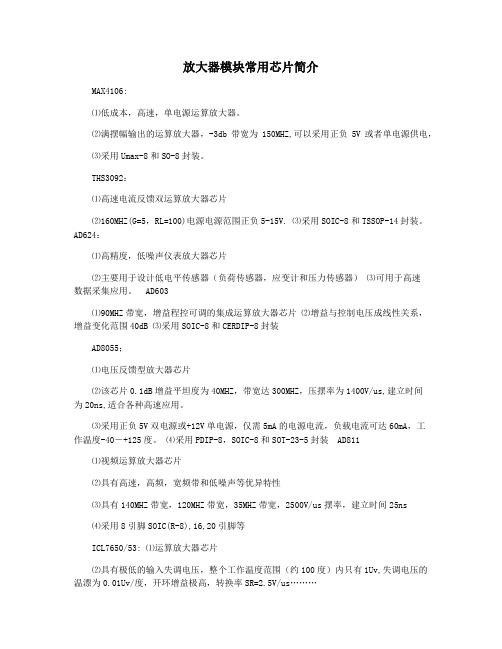
放大器模块常用芯片简介MAX4106:⑴低成本,高速,单电源运算放大器。
⑵满摆幅输出的运算放大器,-3db带宽为150MHZ,可以采用正负5V或者单电源供电,⑶采用Umax-8和SO-8封装。
THS3092:⑴高速电流反馈双运算放大器芯片⑵160MHZ(G=5,RL=100)电源电源范围正负5-15V. ⑶采用SOIC-8和TSSOP-14封装。
AD624:⑴高精度,低噪声仪表放大器芯片⑵主要用于设计低电平传感器(负荷传感器,应变计和压力传感器)⑶可用于高速数据采集应用。
AD603⑴90MHZ带宽,增益程控可调的集成运算放大器芯片⑵增益与控制电压成线性关系,增益变化范围40dB ⑶采用SOIC-8和CERDIP-8封装AD8055;⑴电压反馈型放大器芯片⑵该芯片0.1dB增益平坦度为40MHZ,带宽达300MHZ,压摆率为1400V/us,建立时间为20ns,适合各种高速应用。
⑶采用正负5V双电源或+12V单电源,仅需5mA的电源电流,负载电流可达60mA,工作温度-40―+125度。
⑷采用PDIP-8,SOIC-8和SOT-23-5封装 AD811⑴视频运算放大器芯片⑵具有高速,高频,宽频带和低噪声等优异特性⑶具有140MHZ带宽,120MHZ带宽,35MHZ带宽,2500V/us摆率,建立时间25ns⑷采用8引脚SOIC(R-8),16,20引脚等ICL7650/53: ⑴运算放大器芯片⑵具有极低的输入失调电压,整个工作温度范围(约100度)内只有1Uv,失调电压的温漂为0.01Uv/度,开环增益极高,转换率SR=2.5V/us………⑶电源电压范围V+到V-为4.5-16V.LM386⑴音频功率放大器⑵工作电压4-12V,5-18V静态功耗约4mA可用于电池供电,电压增益范围20-200,可调;⑶采用8引线双列直插式,贴片式封装 TEA2050⑴双声道立体声音频功率放大集成电路芯片⑵工作电源电压3-15V,工作电压6-9V,输出功率与电源电压和扬声器阻抗有关⑶采用POWERDIP16和SO20封装 LTC1068⑴开关电容滤波器芯片⑵它包含4个同样的二阶滤波器。
- 1、下载文档前请自行甄别文档内容的完整性,平台不提供额外的编辑、内容补充、找答案等附加服务。
- 2、"仅部分预览"的文档,不可在线预览部分如存在完整性等问题,可反馈申请退款(可完整预览的文档不适用该条件!)。
- 3、如文档侵犯您的权益,请联系客服反馈,我们会尽快为您处理(人工客服工作时间:9:00-18:30)。
Freescale Semiconductor Application NoteThis application note describes a procedure that is intended to allow users to validate the implementation of1588-specific hardware in their system. Suitable as either a hardware unit test or as a diagnostic tool, this procedure provides verification of the 1588-specific hardware in a simple system environment.This document applies to the following chips:•MPC8306•MPC8308•MPC8309•MPC8377E•MPC8378E•MPC8379E•MPC8535E•MPC8536E•MPC8572E•QorIQ family of chipsDocument Number:AN4326Rev. 0, 07/2011Contents1.IEEE1588 overview . . . . . . . . . . . . . . . . . . . . . . . . . . 22.Freescale support of IEEE1588 . . . . . . . . . . . . . . . . . 23.Routing IEEE1588 signals to a connector . . . . . . . . . 24.Required hardware setup for verification . . . . . . . . . . 35.Required software setup for verification . . . . . . . . . . 46.Results of test verification . . . . . . . . . . . . . . . . . . . . . 47.Software source code listing . . . . . . . . . . . . . . . . . . . . 78.Revision history . . . . . . . . . . . . . . . . . . . . . . . . . . . . 13Verification of the IEEE 1588 Interface by Freescale Semiconductor, Inc.Austin, TXIEEE1588 overview1IEEE1588 overviewIEEE1588 is the standard for a precision clock synchronization protocol used for networked measurement and control systems.The standard defines a Precision Time Protocol (PTP) designed to synchronize real-time clocks in a distributed system. PTP is intended for local area networks using multicast communications, including Ethernet. With easy configuration and fast convergence between components, PTP has the targeted accuracy of microseconds (software implementation) and sub-microseconds (hardware implementation). As an extension, Freescale defines a hardware interface, designed to synchronize external events in a distributed system, based on the IEEE1588 precision clock.2Freescale support of IEEE1588Most of the newer chips in the QorIQ and PowerQUICC families provide, when Ethernet is supported, IEEE1588 hardware assist.The hardware assist means the time-stamping is done automatically by hardware, either as soon as the incoming IEEE1588 packets reach hardware, or just before the outgoing IEEE1588 packets leave hardware. This improves the accuracy and reduces software complexity.To accurately interact with external events, most Freescale products that support IEEE1588 also provide an IEEE1588 interface.An IEEE1588 interface is usually comprised of the following pins:•1588_CLK_IN•1588_CLK_OUT•1588_TRIG_IN1•1588_TRIG_IN2•1588_ALARM_OUT1•1588_ALARM_OUT2•1588_PULSE_OUT1•1588_PULSE_OUT2NOTESome products may have only a subset of the pins.3Routing IEEE1588 signals to a connectorBecause the IEEE1588 interface is designed to interact with the external world, the interface is usually not terminated on the board but routed to a connector on the board. As a result, these signals can be connected to any external signals when needed.The following figure shows how each IEEE1588 signal is routed to a connector.Required hardware setup for verificationFigure1. IEEE1588 interface connectorNOTEOften this interface must be validated before full system implementation isavailable or fully defined.4Required hardware setup for verificationTo simplify the procedure involved in verifying the interface, the 1588-specific hardware signals are configured such that output signals are driven in a defined, programmed manner, based on the input signals. The test is implemented by running the supplied code then applying the proper signals to the three input pins and measuring the signals at the five output pins.The verification may be simplified by using the outputs of 1588_PULSE_OUT1 and 1588_PULSE_OUT2 to drive 1588_TRIG_IN1 and 1588_TRIG_IN2. In this case, only one input and three outputs need to be measured.The following figure illustrates the hardware setup required to verify the IEEE1588 interface.NOTEThe example input clock frequency is 66.66MHz. The expected results are33.33MHz, 66.66Hz, and 133.33Hz.Figure2. Hardware setup to verify the IEEE1588 interfaceRequired software setup for verificationThe signals verified, frequencies used, and relationships between the inputs and outputs are used, as an example, to validate all the 1588-specific signals in a typical use case. With minor changes, and while the input/output signal frequencies that are provided and measured are within product specifications, the supplied code can support fewer signals at different frequencies and input/output relationships, as required by the specific design.5Required software setup for verificationAccording to the hardware setup, software must configure the 1588 module as follows:1.Select the external clock as the clock source.2.Select bypass mode.3.Establish the proper divider factor (divided by 2) for the clock output.4.Set the counting-down counter (1000000) and enable PULSE_OUT1.5.Set the counting-down counter (500000) and enable PULSE_OUT2.6.Enable the 1588 module.7.Start an endless loop, which initiates the following actions:—Monitor and detect triggers on TRIG_IN1.—Calculate the period (average time between triggers) for TRIG_IN1.—Start an alarm on ALARM_OUT1 using the period of TRIG_IN1.—Monitor the alarm on ALARM_OUT1 and start a new alarm if it expires.—Monitor and detect triggers on TRIG_IN2.—Calculate the period (average time between triggers) for TRIG_IN2.—Start an alarm on ALARM_OUT2 using the period of TRIG_IN2.—Monitor the alarm on ALARM_OUT2 and start a new alarm if it expires.6Results of test verificationThe following figures illustrate the test results for the TSEC_1588_CLK_IN and TSEC_1588_CLK_OUT pins, the TSEC_1588_ALARM_OUT1 pin, and the TSEC_1588_ALARM_OUT2 pin.Results of test verification Figure3 provides an illustration of the test result for the TSEC_1588_CLK_IN andTSEC_1588_CLK_OUT pins.NOTEThe top waveform is the 66.66MHz input to TSEC_1588_CLK_IN; thebottom waveform is the 33.33MHz output from TSEC_1588_CLK_OUT.Figure3. Test result for input and output clocksResults of test verificationFigure4 provides an illustration of the test result for the TSEC_1588_ALARM_OUT1 pin (waveform measured at the TSEC_1588_ALARM_OUT1 pin).NOTEThe 66.66Hz pulse output is from 1588_ALARM_OUT1, which wascaptured on the scope using infinite trigger.Figure4. Test result for TSEC_1588_ALARM_OUT1Software source code listing Figure5 provides an illustration of the test result for the TSEC_1588_ALARM_OUT2 pin (waveform measured at the TSEC_1588_ALARM_OUT2 pin).NOTEThe 133.33Hz pulse output is from 1588_ALARM_OUT2, which wascaptured on the scope using infinite trigger.Figure5. Test result for TSEC_1588_ALARM_OUT27Software source code listingThe following is the source code listing. Although prepared for P1023RDB, this code also works with other Freescale products and boards with minor changes./******************************************************************************The following example code is intended to facilitate the testing of the 1588 interface:1.BASE1588 shall be modified if the CCSRBAR is moved from the default2. Before starting this testing program,a) A proper clock (25MHz to 200MHz) shall be applied to TSEC_1588_CLK_INb) TSEC_1588_ALARM_OUT1 shall be tied to TSEC_1588_TRIG_IN1c) TSEC_1588_ALARM_OUT2 shall be tied to TSEC_1588_TRIG_IN23. After this testing program is started, please measure the followingsignals using a scope (assume the TSEC_1588_CLK_IN is 66.66MHz for example)Software source code listinga) TSEC_1588_CLK_OUT should be TSEC_1588_CLK_IN/2 (33.33MHz)b) TSEC_1588_ALARM_OUT1 should be TSEC_1588_CLK_IN/1000000 (66.66Hz pulses)c) TSEC_1588_ALARM_OUT2 should be TSEC_1588_CLK_IN/500000 (133.33Hz pulses)4. If the measured outputs are as expected, then the test passed5. This program will loop for ever**************************************************************************/#define BASE15880xFF7FE000#define UINT32unsigned int#define UINT64unsigned long long int#define TMR_CTRL*((UINT32 *)(BASE1588 + 0x80))#define TMR_TEVENT*((UINT32 *)(BASE1588 + 0x84))#define TMR_TEMASK*((UINT32 *)(BASE1588 + 0x88))#define TMR_CNT_H*((UINT32 *)(BASE1588 + 0x98))#define TMR_CNT_L*((UINT32 *)(BASE1588 + 0x9C))#define TMR_ADD*((UINT32 *)(BASE1588 + 0xA0))#define TMR_ACC*((UINT32 *)(BASE1588 + 0xA4))#define TMR_PRSC*((UINT32 *)(BASE1588 + 0xA8))#define TMROFF_H*((UINT32 *)(BASE1588 + 0xB0))#define TMROFF_L*((UINT32 *)(BASE1588 + 0xB4))#define TMR_ALARM1_H*((UINT32 *)(BASE1588 + 0xB8))#define TMR_ALARM1_L*((UINT32 *)(BASE1588 + 0xBC))#define TMR_ALARM2_H*((UINT32 *)(BASE1588 + 0xC0))#define TMR_ALARM2_L*((UINT32 *)(BASE1588 + 0xC4))#define TMR_FIPER1*((UINT32 *)(BASE1588 + 0xD0))#define TMR_FIPER2*((UINT32 *)(BASE1588 + 0xD4))#define TMR_ETTS1_H*((UINT32 *)(BASE1588 + 0xE0))#define TMR_ETTS1_L*((UINT32 *)(BASE1588 + 0xE4))#define TMR_ETTS2_H*((UINT32 *)(BASE1588 + 0xE8))#define TMR_ETTS2_L*((UINT32 *)(BASE1588 + 0xEC))int main(){UINT32 reg_tmp, reg_tmp_h;Software source code listing UINT32trigger1_started = 0;UINT64 trigger1_prev_time;UINT64 trigger1_next_time;UINT64 trigger1_period;UINT32trigger2_started = 0;UINT64 trigger2_prev_time;UINT64 trigger2_next_time;UINT64 trigger2_period;UINT32trigger2_started = 0;UINT64 trigger2_prev_time;UINT64 trigger2_next_time;UINT64 trigger2_period;UINT32trigger1_output = 0;UINT64 trigger1_alarm;UINT32trigger2_output = 0;UINT64 trigger2_alarm;TMR_CTRL = 0x00010008;//external and bypassTMROFF_L = 1;//just ticksTMROFF_H = 0;TMR_CNT_L = 0;TMR_CNT_H = 0;//start with 0 tickTMR_PRSC = 2;//divide by 2TMR_FIPER1 = 1000000;//1xHzTMR_FIPER2 = 500000;//2xHzTMR_TEVENT = 0xFFFFFFFF;//clear eventsTMR_CTRL = 0x0001000C;//enablewhile(1){//trigger1if(trigger1_started){reg_tmp = TMR_TEVENT & 0x01000000;//trigger1 eventif(reg_tmp)Software source code listing{TMR_TEVENT = 0x01000000;//clear the eventreg_tmp = TMR_ETTS1_H;trigger1_next_time = (UINT64)reg_tmp;trigger1_next_time = trigger1_next_time << 32;reg_tmp = TMR_ETTS1_L;trigger1_next_time = trigger1_next_time + (UINT64)reg_tmp;trigger1_period = trigger1_next_time - trigger1_prev_time;trigger1_prev_time = trigger1_next_time;}}else{reg_tmp = TMR_TEVENT & 0x01000000;//trigger1 eventif(reg_tmp){TMR_TEVENT = 0x01000000;//clear the eventreg_tmp = TMR_ETTS1_H;trigger1_prev_time = (UINT64)reg_tmp;trigger1_prev_time = trigger1_prev_time << 32;reg_tmp = TMR_ETTS1_L;trigger1_prev_time = trigger1_prev_time + (UINT64)reg_tmp;trigger1_period = 0x4FFFFFFFFFFFFFFF;trigger1_started = 1;//new trigger}}//output1if(trigger1_output){reg_tmp = TMR_TEVENT & 0x00010000;//output1 eventif(reg_tmp){TMR_TEVENT = 0x00010000;//clear the eventtrigger1_output = 0;//output doneSoftware source code listing }}else{if(trigger1_started && (trigger1_period != 0x4FFFFFFFFFFFFFFF)){reg_tmp = TMR_CNT_L;reg_tmp_h = TMR_CNT_H;trigger1_next_time = (UINT64)reg_tmp_h;trigger1_next_time = trigger1_next_time << 32;trigger1_next_time = trigger1_next_time + (UINT64)reg_tmp;trigger1_alarm = trigger1_next_time + trigger1_period;reg_tmp = (UINT32)trigger1_alarm;TMR_ALARM1_L = reg_tmp;reg_tmp = (UINT32)(trigger1_alarm >> 32);TMR_ALARM1_H = reg_tmp;trigger1_output = 1;//turn on output}}//trigger2if(trigger2_started){reg_tmp = TMR_TEVENT & 0x02000000;//trigger2 eventif(reg_tmp){TMR_TEVENT = 0x02000000;//clear the eventreg_tmp = TMR_ETTS2_H;trigger2_next_time = (UINT64)reg_tmp;trigger2_next_time = trigger2_next_time << 32;reg_tmp = TMR_ETTS2_L;trigger2_next_time = trigger2_next_time + (UINT64)reg_tmp;trigger2_period = trigger2_next_time - trigger2_prev_time;trigger2_prev_time = trigger2_next_time;}}Software source code listingelse{reg_tmp = TMR_TEVENT & 0x02000000;//trigger2 eventif(reg_tmp){TMR_TEVENT = 0x02000000;//clear the eventreg_tmp = TMR_ETTS2_H;trigger2_prev_time = (UINT64)reg_tmp;trigger2_prev_time = trigger2_prev_time << 32;reg_tmp = TMR_ETTS2_L;trigger2_prev_time = trigger2_prev_time + (UINT64)reg_tmp;trigger2_period = 0x4FFFFFFFFFFFFFFF;trigger2_started = 1;//new trigger}}//output2if(trigger2_output){reg_tmp = TMR_TEVENT & 0x00020000;//output2 eventif(reg_tmp){TMR_TEVENT = 0x00020000;//clear the eventtrigger2_output = 0;//output done}}else{if(trigger2_started && (trigger2_period != 0x4FFFFFFFFFFFFFFF)){reg_tmp = TMR_CNT_L;reg_tmp_h = TMR_CNT_H;trigger2_next_time = (UINT64)reg_tmp_h;trigger2_next_time = trigger2_next_time << 32;trigger2_next_time = trigger2_next_time + (UINT64)reg_tmp;Revision historytrigger2_alarm = trigger2_next_time + trigger2_period;reg_tmp = (UINT32)trigger2_alarm;TMR_ALARM2_L = reg_tmp;reg_tmp = (UINT32)(trigger2_alarm >> 32);TMR_ALARM2_H = reg_tmp;trigger2_output = 1;//turn on output}}}}8Revision historyThe following table provides a revision history for this application note.Table1. Document revision historyRev.Date Substantive change(s)number007/2011Initial public releaseDocument Number:AN4326 Rev. 007/2011Information in this document is provided solely to enable system and software implementers to use Freescale Semiconductor products. There are no express or implied copyright licenses granted hereunder to design or fabricate any integrated circuits or integrated circuits based on the information in this document.Freescale Semiconductor reserves the right to make changes without further notice to any products herein. Freescale Semiconductor makes no warranty, representation or guarantee regarding the suitability of its products for any particular purpose, nor does Freescale Semiconductor assume any liability arising out of the application or use of any product or circuit, and specifically disclaims any and all liability, including without limitation consequential or incidental damages. “Typical” parameters which may be provided in Freescale Semiconductor data sheets and/or specifications can and do vary in different applications and actual performance may vary over time. All operating parameters, including “Typicals” must be validated for each customer application by customer’s technical experts. Freescale Semiconductor does not convey any license under its patent rights nor the rights of others. Freescale Semiconductor products are not designed, intended, or authorized for use as components in systems intended for surgical implant into the body, or other applications intended to support or sustain life, or for any other application in which the failure of the Freescale Semiconductor product could create a situation where personal injury or death may occur. Should Buyer purchase or use Freescale Semiconductor products for any such unintended or unauthorized application, Buyer shall indemnify and hold Freescale Semiconductor and its officers, employees, subsidiaries, affiliates, and distributors harmless against all claims, costs, damages, and expenses, and reasonable attorney fees arising out of, directly or indirectly, any claim of personal injury or death associated with such unintended or unauthorized use, even if such claim alleges that Freescale Semiconductor was negligent regarding the design or manufacture of the part.How to Reach Us:Home Page:Web Support:/supportUSA/Europe or Locations Not Listed: Freescale Semiconductor, Inc.T echnical Information Center, EL516 2100 East Elliot RoadT empe, Arizona 852841-800-521-6274 or+1-480-768-2130/supportEurope, Middle East, and Africa: Freescale Halbleiter Deutschland GmbH T echnical Information Center Schatzbogen 781829 Muenchen, Germany+44 1296 380 456 (English)+46 8 52200080 (English)+49 89 92103 559 (German)+33 1 69 35 48 48 (French)/supportJapan:Freescale Semiconductor Japan Ltd. HeadquartersARCO T ower 15F1-8-1, Shimo-Meguro, Meguro-kuT okyo 153-0064Japan0120 191014 or+81 3 5437 9125support.japan@Asia/Pacific:Freescale Semiconductor China Ltd. Exchange Building 23FNo. 118 Jianguo RoadChaoyang DistrictBeijing 100022China+86 10 5879 8000@ For Literature Requests Only: Freescale Semiconductor Literature Distribution Center 1-800 441-2447 or+1-303-675-2140Fax: +1-303-675-2150 LDCForFreescaleSemiconductor @ Freescale, the Freescale logo, QorIQ and PowerQUICC are trademarks of Freescale Semiconductor, Inc., Reg. U.S. Pat. & Tm. Off. QorIQ Qonverge, and QUICC Engine are trademarks of Freescale Semiconductor, Inc. All other product or service names are the property of their respective owners. The Power Architecture and word marks and the Power and logos and related marks are trademarks and service marks licensed by .© 2011 Freescale Semiconductor, Inc.。