DIN-64MS-L22-A1C1中文资料
MS-2电路断路器和过载保护器测试设备说明书
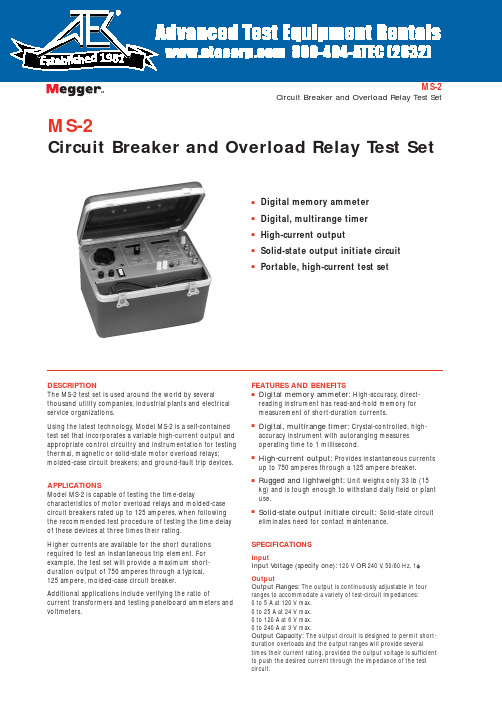
MS-2Circuit Breaker and Overload Relay Test SetsDigital memory ammeter sDigital, multirange timer sHigh-current outputsSolid-state output initiate circuit sPortable, high-current test setMS-2Circuit Breaker and Overload Relay Test SetDESCRIPTIONThe MS-2 test set is used around the world by severalthousand utility companies, industrial plants and electrical service organizations.Using the latest technology, Model MS-2 is a self-contained test set that incorporates a variable high-current output and appropriate control circuitry and instrumentation for testing thermal, magnetic or solid-state motor overload relays;molded-case circuit breakers; and ground-fault trip devices.APPLICATIONSModel MS-2 is capable of testing the time-delaycharacteristics of motor overload relays and molded-case circuit breakers rated up to 125 amperes, when following the recommended test procedure of testing the time delay of these devices at three times their rating.Higher currents are available for the short durations required to test an instantaneous trip element. For example, the test set will provide a maximum short-duration output of 750 amperes through a typical, 125 ampere, molded-case circuit breaker.Additional applications include verifying the ratio ofcurrent transformers and testing panelboard ammeters and voltmeters.FEATURES AND BENEFITSs Digital memory ammeter:High-accuracy, direct-reading instrument has read-and-hold memory for measurement of short-duration currents.sDigital, multirange timer:Crystal-controlled, high-accuracy instrument with autoranging measures operating time to 1 millisecond.sHigh-current output:Provides instantaneous currents up to 750 amperes through a 125 ampere breaker.sRugged and lightweight:Unit weighs only 33 lb (15kg) and is tough enough to withstand daily field or plant use.sSolid-state output initiate circuit:Solid-state circuit eliminates need for contact maintenance.SPECIFICATIONSInputInput Voltage (specify one):120 V OR 240 V , 50/60 Hz, 1f OutputOutput Ranges:The output is continuously adjustable in four ranges to accommodate a variety of test-circuit impedances:0 to 5 A at 120 V max. 0 to 25 A at 24 V max.0 to 120 A at 6 V max. 0 to 240 A at 3 V max.Output Capacity:The output circuit is designed to permit short-duration overloads and the output ranges will provide severaltimes their current rating, provided the output voltage is sufficient to push the desired current through the impedance of the test circuit.1981MS-2 Circuit Breaker and Overload Relay Test SetThe test set is capable of testing the time-delay characteristics of devices rated up to 125 A using a test current of three times their rating (375 A). Additionally, to perform an instantaneous trip test, it will provide 750 A through a typical, 125 A, molded-case circuit breaker connected with the test leads provided with the test set. Overload Capability:T o increase use of the test set, it is designed so that the current ratings may be exceeded for short durations. Because the magnitude of the output current is determined by the impedance of the load circuit, the voltage rating must be sufficient to push the desired current through the device under test and the connecting test leads.Percent Rated Maximum MinimumCurrent Time On Time Off100 (1x)30 min30 min200 (2x) 3 min8 min300 (3x)30 s 4 min400 (4x)7 s 2 minOutput Initiate Circuit:The test set uses a solid-state output initiating circuit. T o increase reliability and eliminate contact maintenance, this circuit uses a triac instead of a contactor to initiate the output.The initiating circuit provides momentary and maintained modes to control output duration. The momentary mode is used whenever the output is to be on for a short duration, such as when performing instantaneous trip tests, or to avoid damage or overheating of the device under test while setting the test current. In the maintained mode, the output remains energized until manually turned off or, when performing timing tests, until the device under test operates — which both stops the timer andde-energizes the output.INSTRUMENTATIONAmmeterOperating Modes (switch-selected)MemoryNormalDisplay31/2digit, extra-bright LED display with 0.3 in. (7.62mm) numerals Ranges (switch-selected)0 to 1.999/19.99/199.9/750 A ContinousAccuracy (overall ammeter system)±1% of reading, ±1 digit on three high rangesRegulating:±1% of range, ±1 digit on low rangeTimerDisplay5-digit, extra-bright, LED display with 0.3 in. (7.62mm) numerals Ranges (switch-selected)0 to 99.999 s0 to 999.99 s0 to 99999 cyclesAccuracy±0.005% of reading, ±1 digitTimer Control CircuitThis circuit automatically starts the timer when the output is energized and automatically stops the timer and de-energizes the output when the device under test operates. This circuit accommodates the following test conditions by simple switch selection of the appropriate mode:Current Actuated:Used to test a device that has no auxiliary contacts to monitor, such as a single-pole circuit breaker. The timer stops when the output current is interrupted.Normally Closed:Used to test a device with normally closed contacts. The timer stops and the output is de-energized when the contacts open.Normally Open:Used to test a device with normally open contacts. The timer stops and the output is de-energized when the contacts close.EnclosureThe test set is housed in a high strength, molded, suitcase-type enclosure with carrying handle and removable cover. Storage space is provided for test leads.Dimensions9.9 H x 14 W x 11 D in.(25 H x 35 W x 28 D cm)Weight33 lb (15 kg)UKArchcliffe Road Dover CT17 9EN EnglandT +44 (0) 1304 502101 F +44 (0) 1304 207342UNITED STATES4271 Bronze WayDallas TX75237-1088 USAT 800 723 2861 (USA only)T +1 214 330 3203F +1 214 337 3038OTHER TECHNICAL SALES OFFICESValley Forge USA, Toronto CANADA,Mumbai INDIA, Trappes FRANCE,Sydney AUSTRALIA, Madrid SPAINand the Kingdom of BAHRAIN.Registered to ISO 9001:2000 Reg no. Q 09290Registered to ISO 14001 Reg no. EMS 61597MS2_DS_en_V10Megger is a registered trademark。
MS5611-01BA03气压计(高度计)中文资料(最详细的)

0.9uA 100nF 最小 7.40 3.72 1.88 0.95 0.48 典型 24 8.22 4.13 2.08 1.06 0.54 最大 9.04 4.54 2.28 1.17 0.60
转换时间 (ms)
tc
气压值输出特征 温度值输出特征 数字输入(CSB,I2C,DIN,SCLK) 气压输出(I2C,DOUT)
sbit SCL=P0^1; sbit SDA=P0^2;
来自主机 S = 开始命令 W = 写命令 A =应答 来自从机 P = 停止命令 R =读命令 N = 无应答 I2C 复位指令
存储器读取时序
PROM读指令由两部分构成, 第一部分使系统处于PROM读模式, 第二部分从系统中读 取数据。
来自主机
S = 开始命令
W = 写命令
ቤተ መጻሕፍቲ ባይዱ
A =应答
来自从机 P = 停止命令 R =读命令 N = 无应答 I2C 读存储器指令,地址=011(系数:3)
***注: 原文附录有一些典型测量值的特征曲线可参考。 其中的一些关键点: ADC 的测量值 D1 和 D2 是分别用来测气压和温度的, 且基本成线性关系; 在常温 (20 ℃)或大于常温时,测量误差很小,而温度低于 20℃时,气压和温度测量误差 会明显增大;电源电压为 3V 时,气压和温度测量误差很小,而其它供电电压下 误差会大幅度增加。
SENS 实际温度灵敏度 SENS SENST 1 TCS * dT
c1* 215 (C 3* dT ) / 28
int 64
41
-8589672450
12884705280
2420281617
int 64 int 32
41
艾登Moeller系列NZM模具电路保护器技术数据表说明书

Eaton 281299Eaton Moeller series NZM - Molded Case Circuit Breaker. Circuit-breaker, 3p, 20A, H2-M20General specificationsEaton Moeller series NZM molded casecircuit breaker thermo-magnetic281299149 mm184 mm105 mm2.345 kg RoHS conformIEC/EN 60947 IEC NZMH2-M20Product Name Catalog NumberProduct Length/Depth Product Height Product Width Product Weight Compliances Certifications Model Code20 AIs the panel builder's responsibility. The specifications for the switchgear must be observed.5 kA130 kAMeets the product standard's requirements.Is the panel builder's responsibility. The specifications for the switchgear must be observed.Built-in device fixed built-in techniqueFixed20 ADoes not apply, since the entire switchgear needs to be evaluated.Max. 10 segments of 24 mm x 0.8 mm at rear-side connection (punched)Max. 8 segments of 24 mm x 1 mm (2x) at box terminal Min. 2 segments of 9 mm x 0.8 mm at box terminalMin. 2 segements of 16 mm x 0.8 mm at rear-side connection (punched)Max. 10 segments of 16 mm x 0.8 mm at box terminalRocker leverMeets the product standard's requirements.40 °C eaton-circuit-breaker-let-through-current-nzm-mccb-characteristic-curve-005.epseaton-circuit-breaker-characteristic-power-defense-mccb-characteristic-curve-037.epsMH2-M20il01206006z2015_11.pdfVorstellung des neuen digitalen Leistungsschalter NZMDas neue digitale NZM-Sortiment - In Kurze verfugbar DEDA-CD-nzm2_3pDA-CS-nzm2_3peaton-manual-motor-starters-starter-msc-r-reversing-starter-wiring-diagram.epseaton-manual-motor-starters-starter-nzm-mccb-wiring-diagram.epseaton-nzm-technical-information-sheeteaton-circuit-breaker-nzm-mccb-dimensions-019.epsRated operational current for specified heat dissipation (In) 10.11 Short-circuit ratingRated short-circuit breaking capacity Ics (IEC/EN 60947) at 690 V, 50/60 HzRated short-circuit breaking capacity Icu (IEC/EN 60947) at 400/415 V, 50/60 Hz10.4 Clearances and creepage distances10.12 Electromagnetic compatibilityMounting MethodAmperage Rating10.2.5 LiftingTerminal capacity (copper strip)Handle type10.2.3.1 Verification of thermal stability of enclosuresAmbient storage temperature - min Characteristic curveeCAD model Installationsanleitung Installationsvideos mCAD modelSchaltpläneTechnische Datenblätter ZeichnungenFitted with:Thermal protectionProtection against direct contactFinger and back-of-hand proof to VDE 0106 part 100Terminal capacity (copper busbar)Max. 24 mm x 8 mm direct at switch rear-side connectionM8 at rear-side screw connectionMin. 16 mm x 5 mm direct at switch rear-side connection10.8 Connections for external conductorsIs the panel builder's responsibility.Special featuresMaximum back-up fuse, if the expected short-circuit currents at the installation location exceed the switching capacity of the circuit breaker (Rated short-circuit breaking capacity Icn) Rated current = rated uninterrupted current: 20 A Tripping class 10 A IEC/EN 60947-4-1, IEC/EN 60947-2 The circuit-breaker fulfills all requirements for AC-3 switching category.Ambient operating temperature - max70 °CClimatic proofingDamp heat, cyclic, to IEC 60068-2-30Damp heat, constant, to IEC 60068-2-78Terminal capacity (aluminum stranded conductor/cable)25 mm² - 50 mm² (1x) direct at switch rear-side connection25 mm² - 185 mm² (1x) at tunnel terminal25 mm² - 50 mm² (2x) direct at switch rear-side connectionTerminal capacity (copper stranded conductor/cable)25 mm² - 70 mm² (2x) direct at switch rear-side connection25 mm² - 185 mm² (1x) direct at switch rear-side connection25 mm² - 185 mm² (1x) at box terminal25 mm² - 70 mm² (2x) at box terminal25 mm² - 185 mm² (1x) at 1-hole tunnel terminalLifespan, electrical7500 operations at 690 V AC-15000 operations at 690 V AC-310000 operations at 415 V AC-16500 operations at 400 V AC-310000 operations at 400 V AC-16500 operations at 415 V AC-3Electrical connection type of main circuitScrew connectionShort-circuit total breaktime< 10 msRated impulse withstand voltage (Uimp) at main contacts8000 VRated short-circuit breaking capacity Ics (IEC/EN 60947) at 400/415 V, 50/60 Hz130 kA10.9.3 Impulse withstand voltageIs the panel builder's responsibility.Utilization categoryA (IEC/EN 60947-2)Number of polesThree-poleAmbient operating temperature - min-25 °C10.6 Incorporation of switching devices and componentsDoes not apply, since the entire switchgear needs to be evaluated.10.5 Protection against electric shockDoes not apply, since the entire switchgear needs to be evaluated.Terminal capacity (control cable)0.75 mm² - 1.5 mm² (2x)0.75 mm² - 2.5 mm² (1x)Equipment heat dissipation, current-dependent5.1 WInstantaneous current setting (Ii) - min350 A10.13 Mechanical functionThe device meets the requirements, provided the information in the instruction leaflet (IL) is observed.10.2.6 Mechanical impactDoes not apply, since the entire switchgear needs to be evaluated.10.9.4 Testing of enclosures made of insulating materialIs the panel builder's responsibility.Rated operational current16 A (400 V AC-3)Rated short-circuit breaking capacity Ics (IEC/EN 60947) at 230 V, 50/60 Hz150 kAApplicationUse in unearthed supply systems at 690 V10.3 Degree of protection of assembliesDoes not apply, since the entire switchgear needs to be evaluated.Rated short-circuit making capacity Icm at 240 V, 50/60 Hz330 kARated short-circuit breaking capacity Ics (IEC/EN 60947) at 440 V, 50/60 Hz130 kADegree of protection (IP), front sideIP40 (with insulating surround)IP66 (with door coupling rotary handle)Rated short-circuit making capacity Icm at 525 V, 50/60 Hz105 kARated short-circuit making capacity Icm at 690 V, 50/60 Hz40 kAInstantaneous current setting (Ii) - max350 AOverload current setting (Ir) - min16 A10.2.3.2 Verification of resistance of insulating materials to normal heatMeets the product standard's requirements.10.2.3.3 Resist. of insul. mat. to abnormal heat/fire by internal elect. effectsMeets the product standard's requirements.Lifespan, mechanical20000 operationsOverload current setting (Ir) - max20 AVoltage rating690 V - 690 VTerminal capacity (copper solid conductor/cable)6 mm² - 16 mm² (2x) at box terminal6 mm² - 16 mm² (2x) direct at switch rear-side connection16 mm² (1x) at tunnel terminal10 mm² - 16 mm² (1x) at box terminal10 mm² - 16 mm² (1x) direct at switch rear-side connectionDegree of protection (terminations)IP10 (tunnel terminal)IP00 (terminations, phase isolator and strip terminal)10.9.2 Power-frequency electric strengthIs the panel builder's responsibility.Short-circuit release non-delayed setting - min350 ADegree of protectionIP20 (basic degree of protection, in the operating controls area) IP20Overvoltage categoryIIIRated short-time withstand current (t = 1 s)1.9 kARated impulse withstand voltage (Uimp) at auxiliary contacts 6000 VTerminal capacity (aluminum solid conductor/cable)10 mm² - 16 mm² (2x) direct at switch rear-side connection10 mm² - 16 mm² (1x) direct at switch rear-side connection16 mm² (1x) at tunnel terminalSwitch off techniqueThermomagneticRated short-time withstand current (t = 0.3 s)1.9 kAAmbient storage temperature - max70 °CRated short-circuit breaking capacity Ics (IEC/EN 60947) at 525 V, 50/60 Hz37.5 kAOptional terminalsBox terminal. Connection on rear. Tunnel terminalRelease systemThermomagnetic releasePollution degree310.7 Internal electrical circuits and connectionsIs the panel builder's responsibility.Rated operating power at AC-3, 230 V5.5 kW10.10 Temperature riseThe panel builder is responsible for the temperature rise calculation. Eaton will provide heat dissipation data for the devices.FunctionsMotor protectionShort-circuit release non-delayed setting - max350 AStandard terminalsScrew terminalRated short-circuit making capacity Icm at 400/415 V, 50/60 Hz 330 kARated operating power at AC-3, 400 V7.5 kWTypeCircuit breaker10.2.2 Corrosion resistanceMeets the product standard's requirements.10.2.4 Resistance to ultra-violet (UV) radiationMeets the product standard's requirements.10.2.7 InscriptionsMeets the product standard's requirements.Rated short-circuit making capacity Icm at 440 V, 50/60 Hz 286 kAIsolation500 V AC (between auxiliary contacts and main contacts)300 V AC (between the auxiliary contacts)Number of operations per hour - max120Circuit breaker frame typeNZM2Direction of incoming supplyAs requiredShock resistance20 g (half-sinusoidal shock 20 ms)Eaton Konzern plc Eaton-Haus30 Pembroke-Straße Dublin 4, Irland © 2023 Eaton. Alle Rechte vorbehalten. Eaton ist eine eingetrageneMarke.Alle anderen Warenzeichen sindEigentum ihrer jeweiligenBesitzer./socialmedia1000 VRated insulation voltage (Ui)。
倍尔实验室仪器设备产品手册说明书

®意大利倍尔实验室仪器设备符号电磁力恢复:永久磁铁中的线圈,用于实现最精确的称重高精度称重传感器:应变计通过测量电阻的变化来测量变形RS232 数据接口:通过此接口连接天平与打印机和其他 PC 外围设备。
测量单位:选择天平显示重量时所用测量单位计件:此功能对相同的项目进行计数,有一些参考数量可供选择检重:上限和下限可以各自设置,用于计量和配料。
百分比称重功能:计算样本重量相比于参考重量(100%)的百分比值。
累计功能:测量多个项目的累计重量。
显示总计和当前重量动物称重:在不稳定条件(如称量活动的实验动物等)下提供准确读数。
密度测定功能:准确测定固态物体或液体的密度最大负荷(峰值保持)功能:称量一连串重物时保留峰值重量GLP 设置:允许存储天平、项目和用户的识别数据。
日期和时间日期和时间:天平显示当前的日期和时间多语言:天平的菜单中有多种语言可供选择配方:允许设置配方中每种成分的名称和公差。
自动配料悬挂称重:可以在天平的底面装一个配有挂钩的支架蓄电池:天平内自带蓄电池,或可连接可选外置蓄电池使用电池操作:天平可以使用一组 AA 电池。
统计功能:显示最小值(Min)、最大值(Max)、总和(Sum)、平均值(Average)、标准偏差(Standard Deviation)毛重-净重-皮重:此功能用于同时显示毛重、净重和皮重。
数据库:内置数据库,用于存储数据和干燥方法纺织功能:确定线的名称、测量单位:Tex 、Td 、Nm 、Nc 。
干燥方式:提供干燥过程在不同温度下的曲线红外传感器:非接触,调用“去皮”或“打印”功能而不用接触天平触摸显示屏:此技术用户友好、易于使用、直观易懂。
蓝牙接口:可以连接蓝牙设备USB 接口:可连接 U 盘图:实时干燥过程可视化显示图密码:用户配置文件可以用密码保护内存:最多可以存储 5 种不同的干燥方案RECIPE STATRS 232G L P % WEIGH%UNITSLIMITS– +UNDERPCSACCUANIMALADDPEAKDENSITYCLOCK LANGBATTERYAANETLC-HREM-FRN S RECIPESTATUNDERACCULANGBATTERYAANETDATABASETEXTILETOUCHSENSMODESBLUETOOTHUSBATGRAPHNET DATABASETEXTILE TOUCH SENS MODES USB PASSWORDM E M OGRAPH ET DATABASE TEXTILE TOUCHSENSMODES USB PASSWORDM E M OGRAPH ABASETEXTILE TOUCHSENSMODESUSBPASSWORD M E M O6-7半微量天平M5-HPB系列可读性 0,01mg8-9半微量天平HPB和S HPB系列可读性 0,01mg10分析天平M系列可读性 0,0001g11精密天平MW和LW 系列可读性 0,001g12可读天平M和L系列可读性 0,01g13可读天平L系列可读性 0,1g14-15可读天平M5-RB 和RB系列可读性 0,01g-0,1g16-17水分测定仪i-Thermo和M5-Thermo 系列可读性 0,0001g-0,001g-0,01g18 可读天平S系列可读性 0,001g-0,01g-0,1g可选配件19-21水分测定仪4( n = 标准 q = 可选的 s = 仅限某些型号)5全自动内部校准M5-HPB-425i 420,01Ø 800,03± 0,08M5-HPB-625i 620,01Ø 800,03± 0,08M5-HPB-105i 1020,01Ø 800,05± 0,08M5-HPB-1265Di 62/1200,01/0,1Ø 800,03 / 0,1± 0,08 / ± 0,2M5-HPB-2285Di 82/2200,01/0,1Ø 800,04 / 0,1± 0,08/ ± 0,2M5-HPB-22105Di102/2200,01/0,1Ø 800,05 / 0,1± 0,08 / ± 0,2系列 - 可读性 0,01mg - 0,1mg型号最大秤量 (g)可读性[d](mg)秤盘尺寸(mm)重复性 (mg)线性误差 (mg)②②②②②②ADD G L P % WEIGH %UNITS LIMITS – +PCS ANIMAL PEAK DENSITY CLOCK LANG RECIPE STAT G L PUNDER ACCU PEAK CLOCK LANG BATTERY AANET DATABASE TEXTILE TOUCH MODES BLUETOOTH USB USB GRAPH PASSWORD M E M O RECIPE ADD G L P % WEIGH %LIMITS – +PCS ANIMAL PEAK DENSITY CLOCK LANG RECIPESTAT G L PUNDER ACCU CLOCK LANGBATTERY AANET DATABASE TEXTILE STAT BATTERY AANET DATABASE TEXTILE M5-M214Ai 2200,1Ø 800,1± 0,0003M5-M314Ai 3100,1Ø 800,1± 0,0003M5-HPB 414i4100,1Ø 800,1mg 如果重量 ≤ 220g 0,3mg 从 220g 到 310g 0,35mg 从 310g 到 410g ± 0,0005M5-HPB 514i 5100,1Ø 800,1mg 如果重量 ≤ 220g 0,3mg 从 220g 到 310g 0,35mg 从 310g 到 510g ± 0,0005M5-HPB 614i 6100,1Ø 800,1mg 如果重量 ≤ 220g 0,3mg 从 220g 到 310g 0,35mg 从 310g 到 610g± 0,0005ADDRS 232G L % WEIGH %UNITSLIMITS– +PCS ANIMALPEAK DENSITY LC-HR7附件TX-110 串行打印机 (AC030)用于固体和液体的密度工具包(AC002)串行到 USB 转换器(E1002))串行电缆,用于串行输出到打印机或电脑(E743)8 GB U盘(AC020)触摸屏手写笔(AC021)技术数据n 量程漂移(+10 … +30°C): +/– 2ppm/°Cn外形尺寸 长×宽×高(毫米):345×215×345n 称重室尺寸 长×宽×高(毫米):162×171×225n 电源 110-230 Vac, 50/60 Hz:输出 24 V /500 mA / 13 VAn 净重:7,2 千克静电消除器技术数据n 操作方式: 2分钟或连续运作最多8小时n 臭氧浓度: 0-0.05 ppm(距离离子源2 厘米)n 放电时间: 9 秒/5 厘米,13秒/10 厘米n 环境条件: 0-50°C,20-80% 空气湿度(无冷凝)n 交流适配器: 交流电 100-240V,50-60 HzA主要功能页面使称重操作更简单百分比称量移液器校准清晰简单的GLP功能输入静电消除器与天平整合:在实验室日常操作过程中,静电会在多种待称重的样品上聚积。
PCII行二氧化氯检测仪说明书

准确度检测
由于生产二氧化氯比较困难且存在危险,因此使用氯标准样品来检测 DPD 和甘氨酸(Glycine)试剂。步骤如下: 1. 制备 1mg/L 的自由氯标准样品
a.购买自由氯标准样品(Cat. No. 14268-10) b.从标准样品包装中的分析认证书上确定标准样品的浓度(50-75mg/LCl2)。
*
背景光的使用会降低电池的使用寿命
1-6
仪器按键和显示屏
项目 描述 1 电源/背景光键 2 校零/滚动键 3 MENU(菜单)键 4 数字显示屏 5 量程指示灯 6 量程指示灯 7 菜单指示灯 8 标准曲线校准指示灯 9 电池电量不足指示灯 10 READ/ENTER(读数/输入)键
1-7
仪器帽拴线
如果仪器上标记了该符号,它指的是需要参照使用手册中的操作和/或安 全信息进行操作。
1-5
规格说明
光源:发光二极管(LED)
检测器:硅光电二极管
光度计精确度:±0.0015Abs
滤波带宽:15nm
波长:528nm
吸光度范围:0-2.5Abs
仪器尺寸:3.2×6.1×15.2cm (1.25×2.4×6 英寸)
因子。
在试剂反应时应使用定时器计时,并对所有样品使用相同的时间。
轻轻地摇动样品使试剂混合均匀。切勿剧烈振荡样品管或安瓿瓶。切勿将样 品管倒置。由于 AccuVac Ampuls 安瓿瓶中不含空气,故能够倒置。剧烈地 振荡可能造成反应前挥发性二氧化氯的损失。
一种用于1,5

专利名称:一种用于1,5‑脱水‑D‑山梨醇检测显色试剂专利类型:发明专利
发明人:张伯平,刘佳龙,张远,蔡泽浪,邹佳信,谢芳
申请号:CN201810049362.8
申请日:20180118
公开号:CN107907534A
公开日:
20180413
专利内容由知识产权出版社提供
摘要:本发明提供了一种检测人体血清中1,5‑脱水‑D‑山梨醇含量的Trinder反应显色试剂,其组成为N‑(羧甲基氨基羰基)‑4,4’‑双(二甲胺基)二苯胺钠盐(简称DA‑64)和18‑冠
醚‑6(CAS:17455‑13‑9)。
其特征在于,在DA‑64水溶液中添加18‑冠醚‑6,使DA‑64与所添加的18冠醚‑6形成复合物体系,增加了DA‑64分子在溶液中的稳定性,从而获得具有长期稳定Trinder反应显色试剂。
在液体状态保存下,18‑冠醚‑6类化合物与DA‑64的添加比摩尔比为1:2.5。
本发明延长DA‑64作为Trinder显色剂的稳定性,并用于人体血清中1,5‑脱水‑D‑山梨醇含量的检测。
申请人:深圳市安帝宝科技有限公司
地址:518055 广东省深圳市南山区西丽街道留仙洞工业区顺和达厂区第一栋第七层东-1
国籍:CN
更多信息请下载全文后查看。
IVDR Annex II Technical Documentation 中文

附录II技术文档制造商拟定的技术文档及其摘要(如适用)应以清晰、有条理、易于搜索和明确的方式呈现,尤其应包括本附录中列出的要素。
1、产品描述和特征,包括变体和附件/配件1.1、产品描述和规格a)产品或贸易名字和产品基本描述包括预期用途和预期使用人群b)附录VIPartC提到的制造商分配给器械的UDI-DL基于UDI系统,或产品代码,序列号或其他可参考的标识就会被立马识别c)预期用途包括以下信息:I)检测或测量物质II)功能,例如:筛查、监测、诊断或辅助诊断、预测、伴随诊断III)旨在检测、定义或区分特定疾病、情况和风险因素IV)自动或非自动V)定性、半定量或定量VI)样本类型VII)预期检测人群VIII)预期使用者IX)另外,伴随诊断需要有相关目标人群和相关药品d)检测方法或仪器操作原则的描述e)产品作为医疗器械的理由f)风险等级和分类规则的应用遵循附录VIIIg)组分的描述,和相关组分里活性成分:抗体、抗原、核酸引物(如适用)如适用:h)样本采集、和器械一起提供的运输材料,或推荐使用规格的描述i)对于自动检测的仪器:描述适用的检测性能或专用检测性能j)对于自动检测试剂:描述适用的仪器性能或专用的仪器性能k)描述与器械一起使用的软件引申:TUV l) 拟投放市场的器械的各种配置/变体的说明或完整列表m )描述预期与器械联合使用的配件、其他器械和非器械引申:TUV 解读,单独提供的配件需要单独的标签、说明书、包装和证书1.2、a) 己上市同类产品或制造商已制造产品的概览b) 已在国际市场上销售的类似产品的概览2、制造商提供的信息a) 器械上的标签或包装(例如单一包装、销售包装、运输包装)的语言应被预想销往的成员国接受b )使用说明书语言应该被预想销往的成员国接受3、设计和制造消息3.1、设计信息用于理解器械设计阶段的信息应包括:a )描述与器械一起提供或推荐一起使用的关键组分如抗体、抗原、酶和核酸引物b )对于仪器:描述主要子系统、分析技术例如操作原则、控制原理、专用电脑硬件或软件c )对于仪器和软件:描述整个系统d )对于软件:描述数据解读技术及算法e )对于预期用于自我测试或近患者测试的器械:描述自我测试或近患者测试的适用性设计方面3.2、制造信息a )生产制造过程信息,例如生产过程、装配、成品测试、成品的包装信息。
固定式安装元件介绍

固定式安装元件介绍固定式安装元件(内有特价商品)维纳尔公司为常规布线形式提供了多种固定在导轨或安装板上的固定式安装元件。
熔断器和相应的连接技术满足了国际上对质量和安全的高标准要求。
CUSTO EasyBase熔断器管座节省空间的D01-和D02-熔断器管座具有45mm的标准安装高度。
出线端子具有较大的接线空间及便利的接线条件。
通过双功能端子可实现与各种类型导线的简便的直接连接。
集成式的盖罩和全方位的触摸保护为安装、操作和维护提供了更高的安全性。
TRITON熔断器管座带有全面触摸保护的熔断器管座符合DIN VDE 50274/BGV A3标准。
可卡接安装在符合DIN EN 60715的帽导轨上,也可螺钉安装。
规格1极和3极,适用D01-,D02-,DII-和DIII。
AMBUS EasySwitch圆柱形熔断器座,电流强度为32A(10*38)时,宽度仅为18mm。
短路稳定性达100KA。
触摸保护满足DIN VDE 0106标准的要求。
在690V时能保护最大80A (22*58)的电流回路(在400V时,为125A)。
另外,可提供附加零线,LED 指示器,半导体保护,1000V直流应用以及带有辅助开关等多种选择。
AMBUS EasySwitch Class CC适用符合UL248-4标准的最大电流30A的CC级熔断器。
按照标准,短路稳定性达到200KA。
用于监测熔丝的LED指示器可供选用。
AMBUS J-CarrierQUADRON J-Carrier适用符合UL248-8标准的J级熔断器。
符合标准且短路稳定性达到200KA的熔断器。
带有触摸保护结构,可满足多种使用要求。
NH-熔断器座和零线1级和3极NH-熔断器座保护范围至630A/690V。
与之相配的带有最佳结构的零线也可供选用。
CUSTO EasyBase 集成盖罩双功能接线端子全面防触摸保护。
AMBUS J-Carrier适用J级圆柱形熔断器,符合UL248-8标准最大规格60AAMBUS EasySwitch圆柱形熔断器座触摸保护,结构紧凑共有4种尺寸,最大125A 符合UL和CSA标准。