西默智能流量控制系统(XMNTC)安装配置手册
西默上网行为管理路由器、流量控制路由器、智能无线路由器产品 说明书

本手册仅适用于西默上网行为管理路由器、流量控制路由器、智能无线路由器产品一、配置您的计算机网络设置1、打开路由器的电源开关,等待片刻,当路由器前面板的灯匀速闪烁后,表示路由器已经进入工作状态,可以接受配置。
2、请正确配置计算机的网络配置,并加载TCP/IP协议。
3、由于路由器默认带有DHCP服务,您的计算机会自动获取192.168.0.2-192.168.0.254之间的IP地址,子网掩码为255.255.255.0,网关为192.168.0.1。
4、单击计算机的“开始菜单”→“运行”,在运行中输入cmd,可以使用下面的命令来检查您的计算机和本产品是否正常连通。
如图1-1所示:图1-1 测试连通性如果出现以上显示,表示网络连接正确,可以进行下一步的操作,如果屏幕提示为:Pinging 192.168.1.1 with 32 bytes of data:Request timed outRequest timed outRequest timed outRequest timed out说明设备未正确的安装,可以按照下面的步骤进行检查:1、设备的物理连接是否正确?与计算机网卡相连的双绞线的另一端必须接路由器内网口并且网线两段的网络接口的指示灯必须正常点亮。
2、计算机的TCP/IP协议是否设置正确?您的计算机IP地址必须为192.168.0.*(*的范围2—254),子网掩码为255.255.255.0(即在同一网段)。
二、登录界面将路由器LAN口与计算机连接好后,计算机会自动获取到192.168.1.1/24段地址,在浏览器的地址栏中输入192.168.1.1后,出现用户名和密码对话框,路由器默认的用户名和密码都是admin,然后点击“确定”按钮,即进人路由器配置界面,如图1-2所示:图1-2 路由器配置界面三、内网配置点击“基本设置”中的“内网设置”进入到内网设置界面,您可以看到路由器局域网的相关信息,即局域网的IP地址和子网掩码,分别是192.168.1.1、255.255.255.0,如图1-3所示:图1-3 内网配置界面这是路由器本身默认的配置,若您需要改动这个地址,可以将默认的地址清除后再输入您想要改变的地址,然后点击“保存”按钮,即可生效。
西默WEB应用防火墙(XMWAF)用户手册

西默 web 应用防火墙用户使用手册
2.9 代理上网配置........................................................................................ 23 2.10 NAT 设置 ............................................................................................. 24 2.11 ISP 信息 ............................................................................................... 25 2.12 DHCP 设置 .......................................................................................... 26 3 web 安全 ........................................................................................................... 28 3.1 规则配置................................................................................................ 28 3.2 策略配置................................................................................................ 29 3.3 ARP 防护 ............................................................................................... 30 3.4 IP 黑白名单 ........................................................................................... 31 3.5 URL 访问控制....................................................................................... 32 3.6 网页防篡改............................................................................................ 33 3.7 网页内容审计........................................................................................ 34 3.8 文件防篡改............................................................................................ 35 3.9 飞信告警............................................................................................... 36 3.10 网站漏洞扫描...................................................................................... 37 4 应用交付.......................................................................................................... 38 4.1 负载均衡............................................................................................... 38 4.2 web 加速 ................................................................................................ 39 4.3 缓存设置................................................................................................ 41 5 日志报表........................................................................................................... 43 5.1 访问日志统计........................................................................................ 44 5.2 告警统计............................................................................................... 44
GMC-I Messtechnik GmbH 智能控制系统输入 输出模块24通道操作指南说明书

Operating InstructionsSMART CONTROL | ECSEnergy Management SystemInput/Output Module for 24 Channels3-349-552-032/5.19Table of Contents1.Input/Output Module for 24 Channels (3)1.1Jumper Designations and Functions (4)2.Input/Output Module for 24 Channels and SmartControl Manager (7)2.1Command Type IO24Analog (8)2.2Command Type IO24Meter (10)2.3Command Type IO24Relay (10)2.4Command Type IO24Status (11)2.5Backup Battery (13)3.Characteristic Values (14)4.Repair and Replacement Parts Service, Calibration Center and RentalInstrument Service (16)5Product Support Industry (16)2 GMC-I MesstechnikGmbH1. Input/Output Module for 24 ChannelsThe I/O module for 24 channels expands the SmartControl with 24 additional digital inputs (DI0 through DI23).Furthermore, ports DI18 through DI21 can be configured as switching outputs K1 through K4 by means of jumpers. Ports DI22 and DI23 can be configured as analog outputs with jumpers as well.The module is mounted with the help of the included accessories, and is connected to the expansion port at the SmartControl PCB (at the bottom in the picture) with the included cable.Please observe all safety precautions for assembly and the connection of ports included in the SmartControl user’s manual.GMC-I Messtechnik GmbH 34 GMC-I Messtechnik GmbH 1.1 Jumper Designations and FunctionsThe terminals for ports DI0 through DI23 are designated a and b. The terminals for the digital inputs, for example DI0, are designated a0 and b0. Jumpers for the active or passive digital input mode: If the ports are used as digitalinputs, either sensors with their own power supply or, e.g., floating contacts/reed contacts can be connected. For a more detailed description of this function please refer to the “Digital Inputs ” section in the SmartControl user’s manual. However, the digital input tariff and synchronization functions described in the user’s manu al are not available in this case.Digital in / option:Jumpers for selecting options for the last six digital inputs (DI18 through DI23). Ports DI18 through DI21 can be configured as switching outputs K1 through K4. For example, SV27/SV29 plugged onto 2-3,respectively, configures DI18 as floating NO contact K1. For a more detailed description of the relays please refer to the “Analog Inputs, Relays ” section in the SmartControl user’s manual. The jumpers required for selecting switching outputs K1 through K4 are:SV29/SV27, SV33/SV31, SV38/SV36, SV42/SV40.The following are then available at the terminals, for example for DI18 as switching output K1: DI18a and DI18b, the switching function is configured as a normally open contact (NO). Ports DI22 through DI23 can be configured as analog outputs.The jumpers required for selecting analog outputs ANA0 through ANA1 (command address: 0-1) are:SV37/SV39, SV41/SV43.Function selection for the analog outputs:Required jumpers for ANA0 -> SV30 SV28 SV26Required jumpers for ANA1 -> SV35 SV34 SV32Example ANA0 as 0-10V output -> Jumper plugged onto SV28, SV26.The following are then available at the terminals for DI22:DI22a analog plus (+)DI22b analog ground (-)Example ANA0 as 0-20mA output -> no jumper plugged onto SV30, SV28, SV26The following are then available at the terminals for DI22:DI22a analog plus (+)DI22b analog ground (-)The following combinations are possible for both analog outputs:ANA0 ANA1 Use0-10V 0-10V Common ground0-20mA - Common ground- 0-20mA Common ground0-20mA 0-20mA Electrical isolation required0-10V 0-20mA Electrical isolation required0-20mA 0-10V Electrical isolation requiredWithin this context, electrical isolation means, for example, that the ground terminals at ANA0 and ANA1 are neither connected with each other nor with any external ground terminals.GMC-I Messtechnik GmbH 56GMC-I Messtechnik GmbH Further components:Jumper SV44 (always plugged in) disconnects the reset cable from the main PCB. Briefly unplugging the jumper results in a reset.Jumper SV45 (always open) is used to reinitialize the BBSRAM.LEDs 1 through 24 (red): indicates pulses at inputs DI0 through DI23.LED 30 (green) DIAG, blinks approx. once per second for normal operation.LEDs 25 through 28 (green): status display for the switching outputsLED on = contact closed LED off = contact openSV1 is the interface to the main PCB at the SmartControl (expansion port).The jumpers for active and passive inputs correspond to those of the SmartControl (refer to the “Digital Inputs ” section in the SmartControl user’s manual).The connection terminals for DI0 through DI23 are numbered 49 through 96.2. Input/Output Module for 24 Channelsand SmartControl ManagerThe input/output module for 24 channels is configured with SmartControl Manager software. The “IO24Meter” spreadsheet can be accessed under calibrat ion in the SmartControl Manager:Factor, unit of measure and meter reading can be entered. These entries are written to the SmartControl after c licking the “Accept” button, and all entries can be returned to their default values by clicking the “Reset” button.Click the current reading for setting the meter readings. Change the reading and acknowledge with enter. Save the changes to the SmartContr ol with the button …...“ which then appears.The units of measure entered here are used automatically when the meters are read.Units of measure and meter factors can only be changed here.One of the following IO24 commands can now be entered to a new program in the SmartControl Manager under menu item “programming”:The symbols are located in the middle at the top of the main window.Just click the symbols and drag them to an empty command field. “D/A” means analog, “123” means meter, the third symbol represents a relay, “I/O” means status.GMC-I Messtechnik GmbH 78 GMC-I Messtechnik GmbH 2.1 Command Type IO24AnalogThe address determines the output channel (ANA0=0 or ANA1=1). The command variable determines the analog output value. Any desired reference can be used.Only analog values within the output range are displayed. Larger and smaller values are shortened accordingly.Example: the command variable has the value 15, whereas the value 10 is shown as analog value.The value range of the input value can be further adjusted to the output range by adjusting the slope, etc. of the command variable.By clicking …Test“ a window opens. Upon entering a test value and clicking the “Start”button, the analog output is set to the corresponding value. If no test value is entered, the command variable is used.GMC-I Messtechnik GmbH 910 GMC-I Messtechnik GmbH 2.2 Command Type IO24MeterThe name can be changed in the bottom field in the meter command, and selection can be made as to whether or not writing to flash memory will take place.Furthermore, it can be specified for each input whether or not this value will be stored to flash memory.Attention : If changes are made here (clear or add meter, or use another input), another ID is assigned to the data as of this point in time which must be given special consideration during read-out because the configuration of the data has been changed! Further settings, for example unit of measure, can be entered under “Calibration” -> “IO24Meter”.2.3 Command Type IO24RelayPlease refer to the “SmartControl Manager, Command Type Relay ” section in the user’s manual for the SmartControl with regard to this command type.The functions are the same, only the addresses for DI18 through DI21 in the address field of this command type are 0-3.2.4 Command Type IO24StatusAn IO24 status command can be created for recording status changes.The status command queries all digital inputs at the clock-pulse rate of the measuring cycle. The address field has no significance in this case.Status changes are saved at the clock-pulse rate of the measuring cycle at most. However, data are always saved at the clock-pulse rate of the saving cycle, regardless of whether a status change has taken place or not.By clicking …Test“ -> …Start“, all digital inputs are queried.GMC-I Messtechnik GmbH 1112GMC-I MesstechnikGmbHThe digital inputs u nder the network ID are individually available under menu item …Network Variables“ and can be used for example as reference for system commands.The …Network Variables “ are automatically created with pre-defined values by theSmartControl under …IO24“ commands. They are automatically assigned a new virtual ID which is calculated as follows::Virtual ID = 10,000 + ID of the IO24 command x 100 + No. value.Example for the IO24 status command of digital input 12:Virtual ID = 10,112 = 10,000 + 1 x 100 + 12The values which have been saved to memory can be queried under menu item …Table“ -> …Read-in “.The status of the other inputs is also saved by this command for channel 12.2.5 Backup BatteryThe battery on the PCB is a lithium round cell, type CR2032 3V.It serves to maintain the meter readings in the event of a power failure.If the instrument is stored for a lengthy period of time without being used, we recommend replacing the battery every 2 years.In the case of permanent operation, we recommend replacing the battery every five years. Please supply the instrument with mains power during battery replacement in order to avoid the loss of data. Please be careful in the process, do not remove any cables and do not connect the two poles of the battery holder with each other.GMC-I Messtechnik GmbH 133.Characteristic Values* Actual power consumption depends upon power pack efficiency, as well as any other connected sensors and devices.14 GMC-I Messtechnik GmbHAdditional Documentation / NotesGMC-I Messtechnik GmbH 154. Repair and Replacement Parts Service,Calibration Center andRental Instrument ServiceIf required please contact:GMC-I Service GmbHService CenterBeuthener Str. 4190471 Nürnberg, GermanyPhone: +49 911 817718-0Fax: +49 911 817718-253e-mail:***************************This address is only valid in Germany.Please contact our representatives or subsidiaries forservice in other countries.5 Product Support IndustryIf required please contact:GMC-I Messtechnik GmbHProduct Support Hotline IndustryPhone: +49 911 8602-500Fax: +49 911 8602-340e-mail:*************************************Edited in Germany • Subject to change without notice • PDF version available on the InternetPhone: +49 911 8602-111GMC-I Messtechnik GmbH Fax: +49 911 8602-777Südwestpark 15 e-mail:************************90449 Nürnberg,Germany 16 GMC-I MesstechnikGmbH。
西默智能DNS系统安装配置手册

西默智能DNS系统安装配置手册上海西默通信技术有限公司本手册适用于产品版本:XMDNS V20.0.3声明Copyright@2011-2012上海西默通信技术有限公司(以下简称:西默科技、XIMO)版权所有,保留一切权利。
未经书面许可,任何单位和个人不得擅自摘抄、复制本书内容的部分或全部,并不得以任何形式传播。
由于产品版本升级或者其它原因,本手册内容可能有变更,西默科技保留在没有任何通知或提示的情况下对本手册的内容进行修改的权利。
本手册作为本产品安装配置的指导手册,西默科技会尽力为您提供准确的信息,但西默科技并不确保手册内容完全没有错误,本手册中所有陈述、信息和建议不构成任何明示或暗示的担保。
技术支持地址:上海市闵行区集心路168号1号楼302邮编:201100400服务热线:400-8200-354客服部QQ号码:support@电话:021-3453 7583 3453 7683 3453 7783传真:021-3453 7785前言本书简介《西默智能DNS安装配置手册》主要介绍了西默智能DNS产品的硬件安装、电缆连接、为实现某种产品特性的部署和配置过程。
为了避免可能出现的设备损坏和人身伤害,以及充分发挥本产品的功能特性,在您上架使用本产品之前,建议您仔细阅读本手册。
本手册包含以下章节:第一章:产品介绍,主要介绍产品的外观、电源、散热等。
第二章:安装前的准备,包含安全注意事项和环境要求。
第三章:安装上架,介绍产品的部署方式和安装过程。
第四章:设备配置,分别举例详细介绍不同需求下的配置过程。
本书约定西默智能DNS产品支持全中文的WEB界面操作,在本手册中关于WEB界面的格式约定如下:环境保护本产品符合关于环境保护方面的设计要求,产品的存放、使用和弃置应遵照国家相关法律、法规的要求进行。
目录1产品介绍 (4)1.1引言 (4)1.2产品外观 (4)1.3电源系统 (5)1.4散热系统 (5)2安装前的准备 (6)2.1安全注意事项 (6)2.2一般场所要求 (6)2.2.1环境要求 (6)2.2.2电源考虑 (6)2.2.3警告 (6)3安装上架 (7)3.1部署模式 (7)3.2设备安装 (7)4设备配置 (8)4.1准备配置 (8)4.2西默智能DNS主辅部署模式 (10)4.2.1应用部署背景 (10)4.2.2部署优势 (11)4.2.3详细配置过程 (11)4.2西默智能DNS双机热备部署模式 (20)4.2.1 实现设备的高可用性与容灾性 (20)4.2.2多线路接入实现智能解析 (21)4.2.3部署拓扑 (21)4.2.4 拓扑分析及部署优势 (22)4.2.3功能实现的操作步骤及检测步骤 (22)1产品介绍1.1引言西默智能DNS产品是上海西默通信技术有限公司针当前中国多运营商,运营商间互访存在速度瓶颈的网络现状,提出的一套解决方案。
西默流量控制产品功能
西默流量控制产品功能
1)协议识别
西默流量控制产品,通过自带的协议库支持识别常见的P2P 类应用,并通过自动更新功能保证协议库的最新,自定义协议可以根据您的需要添加,通过DPI技术,深层分析所有数据,对带宽进行管理。
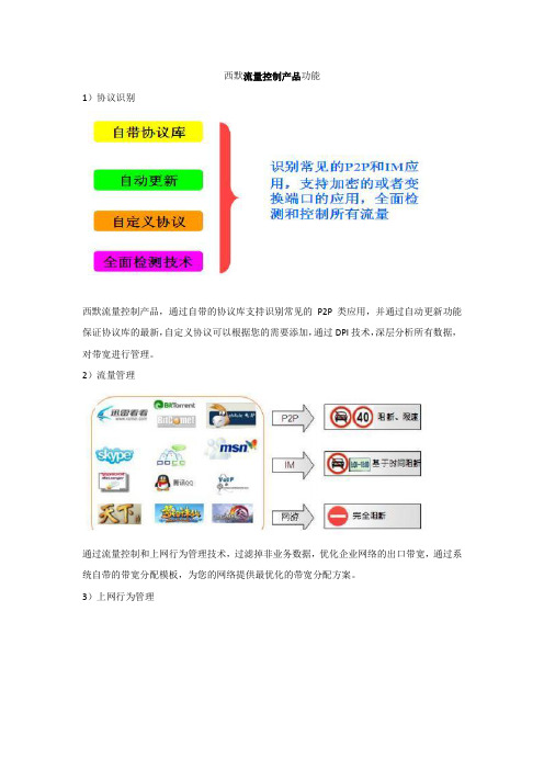
2)流量管理
通过流量控制和上网行为管理技术,过滤掉非业务数据,优化企业网络的出口带宽,通过系统自带的带宽分配模板,为您的网络提供最优化的带宽分配方案。
3)上网行为管理
可以智能对网页的内容和类型进行过滤,有效阻止有病毒和挂马的网站。
⌝系统内置有强大的不法URL 库可以提供定期升级
⌝可以添加和删除网管自定义的网址
⌝可以智能对网页的内容和类型进行过滤,有效阻止有病毒和挂马的网站⌝可以基于时间设置访问网站
同时,所有的日志均保存60 天,使您满足公安部82 号令要求!
4)日志与审计
系统带有完备的日志审计功能,真正做到“事前防范,事发限制,事后跟踪”,使您满足“公安部82令”要求。
5)NAT共享Internet
西默智能流量控制产品支持代理和策略路由功能,因此,在小型企业里可以当作网关设备来使用,从而为您节省投资,独有的策略路由,使双线或者多线接入更加快速、高效。
Siemens Milltronics HydroRanger 200 流量应用配置手册说明书

Siemens Milltronics Process Instruments Inc. 1954 Technology Drive, P.O. Box 4225, Peterborough, ON Canada K9J 7B1 AG040308Flow Application ConfigurationConfiguring the HydroRanger 200 to measure open channel flowSpecific parameter setting to configure the following primary measurement devices: Objective:• exponential devices• Palmer-Bowlus Flume• H-Flume• Universal Linear Flow Calculation • Universal Curved Flow Calculation• BS 3680/ISO 4359 Rectangular Flume• BS 3680/ISO 1438/1 Thin Plate V-Notch WeirEquipment: HydroRanger 200, transducer, IR Hand Held Programmer or Dolphin Plus software, and primarymeasurement device.While every effort was made to verify the following information, no warranty of accuracy or usability is expressed or implied. Overview:This application guide is an addition to the instruction manual. Please review manual to ensure you are familiar with configuring the HydroRanger 200 using the IR Hand Held Programmer or the Dolphin Plus software tool.Setting up the Common ParametersThese parameters are configured for all the open channel flow measuring applications supported by the HydroRanger 200.P001 G 6 Selects Open Channel Flow measurement.P002 G 1 Sets measured material to liquid.P003 G 2 Setsmaximumprocessingspeed, or speed of response, tomedium.P004 G 102 (example) Selects transducer (e.g. 102 = XPS 10) connected to HydroRanger200.P005 G 1 (example) Sets units for head measurement (e.g. 1 = meters).P006 G EmptyDistanceSetsthe distance from zero point of measurement (many timesbottom of the weir or channel) to the sensor surface. Head ismeasured with reference to this zero pointP007 G Span of Headmeasurement Sets the range of head measurement. Often equal to the maximum head.P801 G Range Extension Permits the liquid level to go below the zero point to the amount sethere without indicating an LOE condition (pre-set is 20% of span). * G means ‘global.’ If f you have dual channel unit then the index is either 1 or 2 . For both, select 00.** Here we have chosen one value. Other choices can be selected from the manual as needed.APPLICATION GUIDEAPPLICATION GUIDE Selecting the Primary Measuring Device (P600)The HydroRanger 200 supports the following primary measuring devices to calculate the flow rate based on either the Absolute method or Ratiometric method. The design standards of these devices are programmed in the HydroRanger 200, and it applies the correct standard formula to calculate the flow.If you do not have a primary device, or your primary devices are not included in this list, selecting Universal Linear Flow Calculation or Universal Curved Flow Calculation enables the HydroRanger 200 to calculate the flow rate based on Ratiometric method.P600G(dual channel 1 or2, if both enter 00)Choose from 0 through to 7Select one value from the following list of primary measuring devices and methods per channel application.0 Flow calculation is off and no flow rate or total flow will be calculated None1 Exponentialdevices Ratiometric2 Palmer-BowlusFlume Ratiometric3 H-Flume Ratiometric4 Universal Linear Flow Calculation Ratiometric5 Universal Curved Flow Calculation Ratiometric6 BS-3680/ISO 4359 Rectangular Flume Absolute7 BS-3680/ISO 1438/1 Thin Plate V-notch Weir Absolute Configuring for the Selected Measurement DevicesThe following sections present the calculations required to set the parameter values necessary to configure the applications according to the measuring device.Section 1.0 Exponential Device (P600 = 1)Single exponent devices supported by HydroRanger 200:• V-notch or triangular• Rectangular or Suppressed • Trapezoidal or Cipolleti • Parshall• Leopold Lagco• Cut Throat• any other single exponentprimary measuring device,whose exponent value isknown.APPLICATION GUIDE Section 1.1 Exponential Device Flow Calculation EquationHydroRanger 200 calculates flow rate (Q) based on Ratiometric calculation method using the following exponential equation:Q = Q max(H/H max)XQ Flow rate calculated and displayed by HydroRanger 200. The units will not be displayed and user must know the measurement units (liters/sec. or gallons/min. etc.).Q max Maximum flow (at maximum head H max) as configured in P604. Its value is user provided, and is shown asa standalone number with no units indicated. User must know measurement units used.For example, if maximum flow is 1000 LPS then P604 = 1000 and P606 = secondsH max Maximum Head H max as configured in P603. Its value is provided by the user. Generally the same value asspan configured in P007. The units are defined in P005.x Exponent as configured in P601. Its value is provided by the user. If the value is taken from theHydroRanger 200 manual, it should be verified by the user or with the manufacturer documentation.H Head measured by the ultrasonic head, or any other level measuring device, mounted upstream from theopen channel measuring device. IMPORTANT: set in the same units selected in P005.Section 1.2 Exponential Device Flow Configuration TableSet parameters P601, P603, P604, and P606 to calculated values.P600 Set to 1 (exponential device) Must be configured.P601 Enter the value of exponent x Must be configured.P603 Enter the value of H max.Must be configured.P604 Enter the value of Q max. Must be configured.P606 Time units Must be configured.P605 Zero Head Off-set Optional, configure only when the actual zero is above channelbottom.P607 Flow rate decimal Optional, configured to display the flow rate (Q). Factory set to 2.P620 Low flow cut-off Optional, set to avoid totalizing at flows below this set level.P621 Auto zero head calibration Optional, configure only if head displayed has constant off-set.APPLICATION GUIDE Section 2.0 Palmer-Bowlus Flume (P600 = 2)Section 2.1 Palmer-Bowlus Flume Flow Calculation EquationHydroRanger 200 calculates flow rate (Q) based on Ratiometric calculation method using the following equation:Q = Q max x f(H/ H max)/f(H max/ D)Q Flow rate calculated and displayed by HydroRanger 200. The units will not be displayed and usermust know the measurement units used (liters/sec. or gallons/min. etc.).Q max Maximum flow (at maximum head H max) as configured in P604. Its value is user provided, and isshown as a standalone number with no units indicated. User must know measurement units used.For example, if maximum flow is 1000 LPS then P604 = 1000 and P606 = secondsH max Maximum Head H max as configured in P603. Its value is provided by the user. Generally the samevalue as span configured in P007. The units are defined in P005.H Head measured by the ultrasonic head, or any other level measuring device, mounted upstreamfrom the open channel measuring device. IMPORTANT: set in the same units selected in P005.D Flume width as configured in P602 in the units defined in P005. This Information will be availablefrom the user or by referring to the flume manufacturer’s published discharge tables (e.g. for 30”Palmer Bowlus Flume from Plasti-Fab set P602 to 30 and P005 to inches).Section 2.2 Palmer-Bowlus Flume Configuration TableP600 Set to 2 (Palmer-Bowlus Flume). Must be configured.P602 Enter the value D, the listed flume width. Must be configured.P603 Enter the value of H max.Must be configured.P604 Enter the value of Q max. Must be configured.Must be configured.P605 Zero Head Off-set. The flume is installed inside thepipe and its zero reference is above the zeroreference of the pipe, where transducer monitorsthe head.P606 Time units Must be configured.P607 Flow rate decimal Optional, configured to display the flow rate(Q). Factory set to 2.P620 Low flow cut-off Optional, to avoid totalizing at flows belowthis set level.P621 Auto zero head calibration Optional, configured if displayed head hasconstant off-set.APPLICATION GUIDE Section 3.0: H-Flume (P600)Section 3.1 H-Flume Flow Rate Calculation EquationHydroRanger 200 calculates flow rate (Q) based on Ratiometric calculation method using the following equation:Q = Q max x f(H/ H max)/f(H max/ D)Q Flow rate calculated and displayed by HydroRanger 200. The units will not be displayed and user must know the measurement units used (liters/sec. or gallons/min. etc.).Q max Maximum flow (at maximum head H max) as configured in P604. Its value is user provided, and is shown as a standalone number with no units indicated. User must know measurement units used.For example, if maximum flow is 1000 LPS then P604 = 1000 and P606 = secondsH max Maximum Head H max as configured in P603. Its value is provided by the user. Generally the same valueas span configured in P007. The units are defined in P005.H Head measured by the ultrasonic head, or any other level measuring device, mounted upstream fromthe open channel measuring device. IMPORTANT: set in the same units selected in P005.D Flume height as configured in P602 in the units defined in P005. This Information will be available fromthe user or by referring to the flume manufacturer’s published discharge tables (e.g. for 1.5 ft. H-Flumeset P602 to 1.5 and P005 to feet).Section 3.2 H-Flume Configuration Tableto3 (H-Flume device) Must be configured.P600 SetP602 Enter the value D,the maximum height for the flume. Must be configured.P603 Enter the value of H max. Must be configured.P604 Enter the value of Q max.Must be configured.P605 Zero Head Off-set Configured only when the actual zero isabove channel zero.P606 Time units. Must be configured.P607 Flow rate decimal Optional, configured to display the flow rate(Q). Factory set to 2.P620 Low flow cut-off Optional, to avoid totalizing at flows belowthis set level.P621 Auto zero head calibration Optional, configured if displayed head hasconstant off-set.APPLICATION GUIDE Section 4.0 Universal Linear Flow Calculation (P600 = 4)The HydroRanger 200 uses polynomial function routines to generate a linear curve fitting between the discrete data points (also called break points) entered by the user. A maximum of 32 data points each for head and corresponding flow discharge in the secondary indices of P610 (Head breakpoints) and P611(Flow breakpoints) can be defined. With maximum head value defined in P603 and corresponding maximum flow value defined in P604, a total of 33 discrete points are available to the HydroRanger 200 for flow rate calculation. Use as many data points as possible where flow variations are maximum for increased accuracy.Section 4.1 Universal Linear Flow Calculation EquationThe HydroRanger 200 calculates flow rate (Q) based on Ratiometric calculation method using the following equation:Q = Q max x f(H)/f(H max)Q Flow rate calculated and displayed by HydroRanger 200. The units will not be displayed and user must know the measurement units used (liters/sec. or gallons/min. etc.).Q max Maximum flow (at maximum head H max) as configured in P604. Its value is user provided, and is shown as a standalone number with no units indicated. User must know measurement units used.For example, if maximum flow is 1000 LPS then P604 = 1000 and P606 = seconds.H max Maximum Head H max as configured in P603. Its value is provided by the user. Generally the same valueas span configured in P007. The units are defined in P005.H Head measured by the ultrasonic head, or any other level measuring device, mounted upstream fromthe open channel measuring device. IMPORTANT: set in the same units selected in P005.f(H) CalculatedbyHydroRanger 200 using polynomial function.Section 4.2 Universal Linear Flow Calculation Configuration TableP600 Set to 4 (universal linear flow calculation) Must be configured.P603 Enter the value of H max.Must be configured.P604 Enter the value of Q max.Must be configured.P606 Time units Must be configured.P610 (Secondary Indices 1 – 32max) Sequentially enter from lowest head value in breakpoint 1 (generally 0) and gradually increase up tomaximum 32 head break points. The units are as set inP005.Must be configured.P611 (Secondary Indices 1 – 32max) Sequentially enter corresponding flow values forabove head break points. Start from lowest flow valuein break point 1 (generally 0) and gradually increaseup to maximum 32 flow break points. The time unitsare as set in P606.Must be configured.P605 Zero head off-set Optional, configure only when theactual zero is above channel zero. P607 Flow rate decimal Optional, configured to display theflow rate (Q). Factory set to 2APPLICATION GUIDE P620 Low flow cut-off Optional, to avoid totalizing at flowsbelow this set levelP621 Auto zero head calibration Optional, configured if displayed headhas constant off-setSection 5.0 Universal Curved Flow Calculation (P600 = 5)The HydroRanger calculates the flow rate using the same method as the linear flow calculations. It differs by applying a curved fitting between the discrete points.Section 5.1 Universal Curved Flow Calculation EquationThe HydroRanger 200 calculates flow rate (Q) based on Ratiometric calculation method using the following equation:Q = Q max x f(H)/f(H max)Q Flow rate calculated and displayed by HydroRanger 200. The units will not be displayed and user must know the measurement units used (liters/sec. or gallons/min. etc.).Q max Maximum flow (at maximum head H max) as configured in P604. Its value is user provided, and is shown as a standalone number with no units indicated. User must know measurement units used.For example, if maximum flow is 1000 LPS then P604 = 1000 and P606 = seconds.H max Maximum Head H max as configured in P603. Its value is provided by the user. Generally the same valueas span configured in P007. The units are defined in P005.H Head measured by the ultrasonic head, or any other level measuring device, mounted upstream fromthe open channel measuring device. IMPORTANT: set in the same units selected in P005.f(H) CalculatedbyHydroRanger 200 using polynomial functionSection 5.2 Universal Curved Flow Calculation Configuration TableP600 Setto5 (universal curved flow calculation) Must be configured.P603 Enter the value of H max.Must be configured.P604 Enter the value of Q max. Must be configured.P606 Time units Must be configured.P610 (Secondary Indices 1 – 32max) Enter sequentially from lowest head value in break point 1(generally 0) and gradually increasing up to maximum 32head break points. The units are as set in P005.Must be configured.P611 (Secondary Indices 1 – 32max) Sequentially enter corresponding flow values for abovehead break points starting form lowest flow value inbreak point 1 (generally 0) and gradually increasing up tomaximum 32 flow break points. The time units are as setin P606.Must be configured.P605 Zero Head Off-set Configured only when the actual zerois above channel zeroP607 Flow rate decimal Optional, configured to display theAPPLICATION GUIDEflow rate (Q). Factory set to 2 P620 Low flow cut-off Optional, to avoid totalizing at flowsbelow this set levelP621 Auto zero head calibration Optional, configured if displayedhead has constant off-setSection 6.0 BS-3680/ISO 4359 Rectangular Flume (P600 = 6)For flowrate calculation, this method requires only the physical dimensions of the flume:B Approach channel widthwidthb Throatheightp HumplengthL ThroatSection 6.1 BS-3680/ISO 4359 Rectangular Flume Flow Calculation EquationThe HydroRanger 200 calculates flow rate (Q) based on the Absolute calculation method confirming to BS 3680 Part 4C standard for Rectangular flumes and uses the following equation:Q = (2/3)1.5 x (g)0.5 x Cv x Cs x Cd x B x (h)1.5Q Flow rate calculated and displayed by HydroRanger 200. The units will not be displayed and user must know the measurement units used (liters/sec. or gallons/min. etc.).g Acceleration due to gravityB Throatwidthh Head measured by the ultrasonic head, or any other level measuring device, mounted upstream fromthe open channel measuring device. IMPORTANT: set in the same units selected in P005.C v Velocity coefficient calculated by HydroRanger 200C s Shape coefficient (= 1 here)C d Discharge coefficient calculated by HydroRanger 200APPLICATION GUIDE Section 6.1 BS-3680/ISO 4359 Rectangular Flume Flow Calculation TableP600 Set to 6 (BS 3680/ISO 4359 Rectangular Flume) Must be configured.P602 = (1 – 6) Enter the values of B, b, p & L in indices 1 to 4 respectively. Inindices 5 and 6 you can view calculated values of C v and C drespectivelyMust be configured.P605 Zero Head Off-set Must be configured due to hump height of theflume.P608 Flow rate units Must be configured.P607 Flow rate decimal is configured. Optional, configured to display the flow rate (Q).Factory set to 2.P620 Low flow cut-off (Its optional), to avoid totalizing at flows below this set level. Optional, to avoid totalizing at flows below this set level.P621 Auto zero head calibration (its optional), configured if head displayed has constant off-set. Optional, configured if displayed head has constant off-set.Section 7.0 BS-3680/ISO 1438 Thin plate V notch (P600 = 7)To calculate the flow rate this method requires only the angle of the weir notch () in degrees.Section 7.1 BS-3680/ISO 1438 Thin plate V Notch Flow CalculationThe HydroRanger 200 calculates flow rate (Q) based on Absolute calculation method confirming to BS 3680 Part 4A standard for thin plate weirs using the following equation:Q = C e x (8/15) x tan(/2) x (2g)0.5 x (h)2.5Q Flow rate calculated and displayed by HydroRanger 200. The units will not be displayed and user must know the measurement units used (liters/sec. or gallons/min. etc.).Weir notch angle in degreesg Acceleration due to gravityC e Discharge coefficient and is a function of weir notch angle .h Head measured by the ultrasonic head, or any other level measuring device, mounted upstream fromthe open channel measuring device. IMPORTANT: set in the same units selected in P005.APPLICATION GUIDE Section 7.1 BS3680/ISO 1438/1 V Notch Weir Configuration TableP600 Set to 7 (BS 3680/ISO 1438/1 V Notch Weir) Must be configured.Must be configured.P602 = (1 & 2) Enter the values of in degrees in index 1. Inindex 2, view the value of discharge coefficient C eP603 Enter the value of maximum head in unit as set inMust be configured.P005.P605 Zero Head Off-set Must be configured because the zero of the weiris above the channel zero.P608 Flow rate units Must be configured.P607 Flow rate decimal Optional, configured to display the flow rate (Q).Factory set to 2.P620 Low flow cut-off Optional, to avoid totalizing at flows below thisset level.P621 Auto zero head calibration Optional, configured if displayed head hasconstant off-set.Note: Both Primary devices BS 3680 / ISO 4359 Rectangular Flume and the BS 3680 / ISO 1438/1 Thin Plate V notch weircan also be configured for Ratiometric calculation in case the flow rate units are not supported in P608.。
西莫罗闸机控制软件说明书

西莫罗闸机控制软件说明书Control Software Specification of CMOLO Turnstile1、连接(connecting)1)解压压缩包后找到turnstile.exe文件打开,出现登录界面,在登录界面中可以选择两种通讯方式,RS485和以太网如图A。
图A2)设备列表.连接成功后进入设备列表界面“图B”图B若闸机第一次使用连接使用时候,初始地址为“192.168.1.254”软件则会自动弹出对话框修改地址如“图C”地址可以修改成“192.168.1.2~192.168.1.253”填入修改地址点击“Save”后,重起闸机。
图C3)添加或修改闸机地址,在软件连接界面中点击“Device List(L)”按钮出现闸机地址列表如“图D”在此输入新更改的闸机地址,如“192.168.1.9”输入新地址完毕后点击Save(S)保存,保存成功后软件自动重启回到连接界面。
图D2、设置闸机1)获取闸机信息,勾选需要查看的闸机地址,点击设备列表界面中的“Read Device Info (R)”按钮获取闸机信息如”图E”图E在此界面中可以看到设备的型号、设备类型、和设备序列号。
2)基本设置,点击设备列表界面中的”Basic setting(B)”按钮弹出界面”图F”图F在此界面中可以对闸机设置4个参数1.工作模式有两种状态可选,“NC Mode”和“NO Mode”模式2.进口状态可选4种状态。
3.出口状态可选4种状态。
4.延时关门时间,可设置关门时间(0~999)秒。
勾选需要修改的闸机点击“Save(S)”3)高级设置,点击设备列表界面中的”Advance setting(A)”按钮弹出界面”图G图G在此界面中可查看和清零闸机通行计数,和调整红外感应级别红外感应级别为(0~5)勾选需要修改的闸机点击“Save(S)”4)报警设置,点击设备列表界面中的”Alarm setting(A)”按钮弹出界面”图H”图H5)设备调试,点击设备列表界面中的”System Test(A)”按钮弹出界面”图I图I通过此界面可以对闸机进行4个基本的操作测试Left Open可对闸机进行左向开门.Right Open 可对闸机进行右向开门.Auto Drop 可对闸机进行掉杆测试.(仅对半自动和全自动三辊闸有效) Auto Raise 可对闸机进行自动上杆操作(仅对全自动三辊闸有效)。
西默流量控制路由器(XMSFR)白皮书

西默流量控制系列路由器技术白皮书上海西默通信技术有限公司2012年3月目录1、前言 (3)1.1.1工作效率低下 (4)1.1.2网速越来越慢 (4)1.1.3内部资料泄密 (4)1.2 传统流量控制产品的问题 (5)1.3产品图片 (5)2.产品功能介绍 (6)2.1 基于应用与协议的流控 (6)2.2上网行为管理 (7)2.3 QOS限速 (7)2.4 认证,授权 (7)2.4.1认证 (7)2.4.2授权 (8)2.5 多WAN接入 (8)2.6 上网行为审计 (8)2.7 VPN (9)2.8 企业级的无线(无线路由器产品) (9)3 产品部署 (10)3.1 网关模式 (10)3.2 网桥模式 (10)3.3 审计模式 (10)4 上海西默通信技术有限公司简介 (10)5 成功案例 (11)1、前言进入21世纪,进入网络经济时代,电子商务、Web2.0、远程教育、VoIP等创新应用正在改变着我们的工作和生活方式,据有关组织统计,互联网目前已成为人类社会最重要的信息基础设施,占人类信息交流的80%。
同时,企事业单位为满足其需求也在积极的对网络出口带宽进行扩容,但当今的互联网应用已经越来越多样、越来越复杂,特别是P2P类应用,占用了互联网大部分带宽,以BT和Edonkey为代表的P2P应用已经占据了整个互联网流量的2/3以上,运营商和企业的基础网络建设陷入了“拥塞-扩容-再拥塞”的非正常局面,盈利能力相应降低,关键业务的运行带宽得不到有效的保障。
造成以上现象的主要原因是对用户缺少一个有效的控制和区分手段,网络管理人员既不知道用户在网上干什么,也没有办法给不同用户提供一个不同的服务质量、服务等级的保证。
由于缺乏一个可视化的管理工具,无法实现业务识别、内容计费增加了运营商的运营成本,降低了客户的满意度。
因此,如何深度感知网络应用,提供网络业务控制和管理手段,构建可以运营、可以管理的和谐网络,对P2P有效限制,合理引导,对关键业务应用进行带宽保障,使企业正常应用顺畅运行,是当今广大网络管理人员的头痛问题。
- 1、下载文档前请自行甄别文档内容的完整性,平台不提供额外的编辑、内容补充、找答案等附加服务。
- 2、"仅部分预览"的文档,不可在线预览部分如存在完整性等问题,可反馈申请退款(可完整预览的文档不适用该条件!)。
- 3、如文档侵犯您的权益,请联系客服反馈,我们会尽快为您处理(人工客服工作时间:9:00-18:30)。
西默智能流量控制安装配置手册声明Copyright@2011-2012 上海西默通信技术有限公司(以下简称:西默科技、XIMO)版权所有,保留一切权利。
未经书面许可,任何单位和个人不得擅自摘抄、复制本书内容的部分或全部,并不得以任何形式传播。
由于产品版本升级或者其它原因,本手册内容可能有变更,西默科技保留在没有任何通知或提示的情况下对本手册的内容进行修改的权利。
本手册作为本产品安装配置的指导手册,西默科技会尽力为您提供准确的信息,但西默科技并不确保手册内容完全没有错误,本手册中所有陈述、信息和建议不构成任何明示或暗示的担保。
技术支持地址:上海市闵行区集心路 168 号 1 号楼 302邮编:201100400 服务热线:400-8200-354客服部 QQ 号码:support@电话:021-3453 7583 3453 7683 3453 7783传真:021-3453 7785前言感谢您选择并使用XIMO智能流控产品!XIMO 智能流量分析及控制系统(以下简称XIMO流控),是在互联网P2P(Peer-to-Peer)应用广泛流行的背景下,诞生的新一代应用层QOS产品。
XIMO流控是一款真正意义上的应用层级流控产品,基于连接过程和协议特征识别,对于加密协议采用主动探测引擎,经过一套完整的识别流程,准确识别应用,精确定位具体的软件客户端,把宽带网络的应用可视化和可管理提高到一个新的阶段。
XIMO流控系统能帮助宽带运营网络管理人员实时了解网络应用流量状态及应用概况,通过策略进行灵活可控的流量管理,提升网络运行效率。
应用层流控产品,是一个典型的服务型产品,需要根据互联网应用的变化,不断改进协议识别引擎和更新协议特征库,才能保证流控的效果。
应用层协议识别的重点和难点是P2P 应用,P2P 流控是应用层流控的核心;互联网不断有新增加的应用,已有的应用为了逃避流控设备监管,采用技术对抗方法,伪装和变换协议特征,甚至整个趋势向加密方向发展,这使得流控产品的技术要跟踪、适应或超越这些变化,才能为用户提供良好的服务。
XIMO流控产品,为了适应互联网应用的快速变化,有专门的团队跟踪研究互联网应用变化,采用抓包的方法不断收集分析协议样本,利用自主开发、描述能力强的“协议特征描述语言”—PSDL(Protocol Signature Description Language),维护协议特征库,快速提供给用户升级。
XIMO流控系统,正常 3 个月升级一次版本,1个月升级一次协议特征库。
升级了特征库,将有更多的协议被识别,降低未知流量的比例。
请 XIMO流控产品用户,注意查收最新版本和最新特征库,第一时间升级到最新版本,从而获得更好的流控效果。
在使用过程中,如果发现某个应用未能被正确识别,可以及时向经销商或XIMOSupportCenter反馈(邮件地址:support@ )或直接帮助采集样本,XIMO 在分析获取特征之后添加到协议特征库,通过特征库升级,就能及时解决问题。
XIMO 流控产品,全中文化的 Web界面,界面简洁,操作容易掌握,必要的提示在 Web界面中已经标明,对于有一定技术基础的网管人员,基本可以无需手册指导操作。
但是还是建议,正式上线前,仔细阅读本手册,掌握策略配置的核心思想和流程,从而获得灵活的策略配置管理效果。
目录西默智能流量控制安装配置手册 (1)声明 (1)技术支持 (1)前言 (1)1产品介绍 (1)1.1产品外观 (1)1.2电源系统 (2)1.3散热系统 (2)2安装前准备 (3)2.1安装前注意事项 (3)2.2一般场所要求 (3)3安装上架 (4)3.1部署模式 (4)3.2设备安装 (5)4设备设置 (6)4.1准备配置 (6)4,2网关模式 (8)4.3网桥模式 (11)5、强大的功能 (17)5.1具有完整的上网行为功能, (17)1产品介绍1.1产品外观西默流量控制有11款产品。
产品图如下:XMNTC-1000(4个100M电口,吞吐量30Mbps)XMNTC-1800(4个100M电口,吞吐量50Mbps)XMNTC-2000(4个100M电口,吞吐量100Mbps)XMNTC-2800(4个100M电口,吞吐量200Mbps)XMNTC-3000(6个100M电口,吞吐量500Mbps)XMNTC-5000(6个1000M电口,吞吐量1Gbps)XMNTC-6800(4个1000M电口+2个SFP,吞吐量2.5Gbps)XMNTC-8000(4个1000M电口+4个SFP,吞吐量3Gbps)XMNTC-8800(4个1000M电口+4个SFP,吞吐量4Gbps)XMNTC-12000(8个千M电口+8个SFP,可扩展8个千兆电/光口或2个万兆光口) 1.2电源系统西默流量控制产品双电源支持热插拔、宽输入电压范围以及完善的保护功能,(输出过流、转出短路、输出电压)1.3散热系统西默流量控制产品采用风扇强迫式风冷散热,可保障设备工作温度保持在正常范围。
2安装前准备2.1安装前注意事项为了避免可能出现的设备损坏和人身伤害,请在安装前仔细阅读本安装注意事项,实际安装过程中包含但不限于以下所有安全建议。
1、机箱安装过程中和安装完成后请保持无尘、清洁;2、如果所处环境可能伤害眼睛,请务必戴上防护眼镜;3、不要穿宽松的衣服,以免绊住机箱,系好领带或围巾,卷起袖子;4、把工具放在不易被碰落的地方;5、不要做可能引起人身伤害或损坏设备的操作;6、当接上电源时,不要触摸电源,当心触电;7、设备和电源插座间不正确的连接可能导致危险情况;2.2一般场所要求这部分讨论安全安装和使用系统的场所要求,安装前确保场所已经准备好2.2.1环境要求设备可以装在桌面或机架上。
机箱放置、机架的布置、房间的布线对正常的系统操作相当重要。
设备距离太近、通风不好、难以接近控制板,将造成维护困难或引起系统故障和停机。
2.2.2电源要求检查电源,确保供电系统接地良好,路由器输入端电源稳定可靠,必要时安装电压调节装置。
大楼的短路保护措施中应保证有一个240V,10A 的保险丝或断路器在相线中。
2.2.3警告若供电系统未良好接地,或输入电源抖动过大,存在过度脉冲,都会引起通信设备误码率增加,甚至硬件系统损坏!3安装上架3.1部署模式3.1.1网关模式网关模式是将西默流量控制作为网络出口的网关,通过做NAT代理内网员工上网使用,西默流量控制采用先进的硬件架构,提供高性能NAT转换功能。
3.1.2网桥模式网桥模式不需要改变原来的拓扑及规划,方便实现对内网用户的控制和监控3.2设备安装请按照以下流程将设备正确的安装到您的机柜内:1.)打开包装,清单检查打开设备包装箱后,请取出装箱单,检查箱内配件与清单上的配件数量和规格是否一致(测试机无相关配件)。
2.)设备检查上架前请检查设备硬件,查看外观有无明显损伤。
在极少数情况下,可能会出现因为设备在运输物流环节过程中导致的部件松动或脱落,所以在加电前请晃动设备,检测设备内部有无异常声响,若有异样请及时与我们联系(测试机应注意此检查项目)。
3.)上架固定将西默流量控制安装到机架上,可放在托盘上,然后用螺丝固定(机架/机柜一定良好接地)。
4)线路连接正确插入电源线,双电源设备请连接两条电源5.)加电启动检查所有线缆连接正确无误后,启动设备。
4设备设置4.1准备配置西默上网行为设备支持全中文WEB 界面配置管理,首先应通过线缆连接配置PC 和默认管理口,西默上网行为的管理口为设备正面向上放置时,从右向左数的第一个和第二个接口,地址分别如下:第一个接口:192.168.2.242/24第二个接口:192.168.0.242/24以下以通过第一个接口192.168.2.207 配置为例,详细说明详细的配置过程和方法。
将配置PC(如笔记本)的地址配置成和管理口在一个子网内的地址,如下图所示:在cmd 命令行下测试到管理口是否连接正常:若不通,请检查配置和线缆连接是否正确。
在配置PC 浏览器(建议使用firefox 浏览器)地址栏输入西默管理界面的地址,协议使用https,如下:https://192.168.2.242西默流量控制默认管理员帐号为:用户名:admin密码:111111正确输入登录信息后,进入管理界面下面我们针对不同的需求,不同的部署模式,分别进行详细的阐述。
4,2网关模式4.2.1部署优势网关模式是将西默流量控制作为网络出口的网关,通过做NAT代理内网员工上网使用,西默流量控制采用先进的硬件架构,提供高性能NAT转换功能。
4.2.2详细配置过程需要强调的是西默流控“NTC6000”以上的是没有网关模式的。
假设某公司的默认内网网关是192.168.1.1,公网IP“221.103.2.21”公网网关:221.103.2.1 接口带宽为“1024M”要求做网关的同时也要对员工的上网行为进行管理。
如图:第一步:系统管理→基本系统设置,在基本系统设置中设置默认网关:192.168.1.1。
配置完成后点击保存。
第二步点击网络设置—网络接口设置下图:将光标停留在添加接口上会出现一个下拉菜单,点击普通接口得到下图:配置外网接口,接口类型选择外网接口;。
在IP地址栏中填入外网接口的ip地址,在子网掩码出填入掩码,在接口带宽处填入接口带宽。
内网接口的配置相同。
设置完成后点击保存,接口就配置完成;所有接口配置完成后,点击应用即可生效这样网络接口列表的颜色有红色变为白色。
这表明设置成功。
点击应用网络接口配置之前点击应用网络接口配置之前第三步、配置回程路由在多网段比较复杂的环境中,需要配置回程路由。
在防火墙与路由—静态路由里打开添加静态路由设置在IP段中填入回程路由的路由网段,,下一跳处填入下一跳网关,优先级出填入优先级。
点击保存,确定无误后点击应用静态路由。
这样静态路由就设置完成了。
第四步、配置代理上网,如果内部网络使用的都是私有地址或有特殊需要的话,需要设置代理上网。
在防火墙和路由—代理上网设置。
如图:上网接口选择要代理内部上网的外网接口,指定代理网段或选择代理所有ip,转换源地址为指定上网接口地址(选择使用上网接口),或指定ip段(填入起始ip地址和结束ip地址)。
点击保存。
的下图:确定无误后点击应用NAT设置这样代理上网就设置完成了,如下图:设置完成后单击重启按钮,如下图:重启后所有的设置就完成了,这样西默流控的网关模式就配置完成了。
4.3网桥模式4.3.1 部署优势网桥模式不需要改变原来的拓扑及规划,方便实现对内网用户的控制和监控4.3.2详细配置过程第一步系统默认设置。
点击系统管理—基本系统设置得到下图:在默认网关中输入“192.168.2.1”完成后点击保存。