DSP外文资料17
数字信号处理Digital Signal Processing(DSP)
• 经过A/D变换器后,不但时间离散化了,幅度也量化 了,这种信号称为数字信号。用x(n)表示。
例子
• 如4位码,只能表示24=16种不同的信号幅度, 这些幅度称为量化电平。
• 当离散时间信号幅度与量化电平不相同时, 就要以最接近的一个量化电平来近似它。
(7)估计理论,包括功率谱估计及相关函数 估计等。
(8)信号的压缩,包括语音信号与图象信号 的压缩
(9)信号的建模,包括AR,MA,ARMA, CAPON,PRONY等各种模型。
(10)其他特殊算法(同态处理、抽取与内 插、信号重建等)
(11)数字信号处理的实现。
(12) 数字信号处理的应用。
第一节 什么是数字信号处理 第二节 数字信号处理的实现 第三节 数字信号处理的应用领域 第四节 数字信号处理器
例:直流信号:仅用一个参量可以描述。阶跃信号:可用幅 度和时间两个参量描述。正弦波信号:可用幅度、频率和 相位三个参量来描述。
• 随机信号:若信号在任意时刻的取值不能精确确定,或 说取值是随机的,即它不能用有限的参量加以描述。也无 法对它的未来值确定性地预测。它只能通过统计学的方法 来描述(概率密度函数来描述)。
• 随着信息时代、数字世界的到来,数字信号处 理已成为一门极其重要的学科和技术领域。
(四)数字信号处理系统的基本组成
• 以下所讨论的是模拟信号的数字信号处理系统.
模拟 前置预 滤波器
xa(t)
PrF
x(n)
y(n)
A/D 变换器
数字信号 处理器
D/A 变换器
ADC
DSP
外文翻译---基于DSP技术为机车轴承设计故障诊断监控系统
原文:Design of Fault Diagnosis Monitor System for the LocomotiveBearings Based on DSP TechnologyAbstractThe rolling bearing is one of the key parts of the locomotive running components, because it condition is directly related to the performance and safety of locomotive. In this paper, the monitor system for the locomotive bearings based on DSP TMS320LF2407A is designed. This system diagnoses the rolling bearing fault using vibration analysis method. It is based on comprehensive resonance demodulation and fast Fourier transform technique, and it adopts "related methods" to handle the result of the FFT. It effectively improves the response characteristics, sensitivity, differentiate and measurement accuracy of the bearing failure monitor system, and it can fulfill the monitor and prediction of the transient fault in the course of the locomotive running.Key words: resonance demodulation technology; digital signal processor; related methodsI. IntroductionThe higher safety is required to the trains because its speed is raised constantly. Bearing fault is one of the major factors causing eventful traffic accidents and affecting rail safety. Currently the railway system usually uses the bearing temperature detector to monitor the locomotive bearing condition. Theoretical analysis and a lot of practice show that the bearing temperature detector can prevent accidents from occurring to some extent, but most of the bearing fault is not sensitive to temperature. When the temperature of the bearing is beyond the range and the system gives an alarm, the worse damage of the bearing has occurred, and even theincident had happened. Therefore, to find the fault more early and accurately, the more advanced monitoring means must be adopted. Most of the bearing fault is very sensitive to vibration signal. The fault can cause vibration of the bearing increased. Compared with monitoring the temperature of bearing, the analysis and processing results to the vibration signal has more advantage than the temperature means.II. System composing and work processBased on the need, the monitor of the bearing fault monitoring system to the locomotive bearing sets two detections: itineration detections and fixed detections. The itineration detection is used in the normal conditions, and the fixed detection is used for the continuous monitoring of the fault bearing. The system adopts special composite sensor to collect the vibration of the bearing and the temperature signal at the same time. After the data processing, the corresponding fault levels and rise in temperature are got. The data acquisition unit is designed in this system. Alarm information will be transmitted to all carriages through interfaces so that the staff can handled in time, and the same time, the fault data and the related information of the train such as the current location and speed will be transmitted to the dispatch center through GPS, which is convenient to adopt corresponding measures. The system block diagram is in Fig. 1.III. The key technology of the design for the monitoring systemA.The spectrum analysis means for diagnosing bearing faultUnder normal circumstances, all parts of the rolling bearing (inner circle, outer circle, roller, holding frame) will retain the stable relative movement state. If the surface of some element (except for holding frame) has crack, and this crack is in the surface of the rolling adjacent component, the instantaneous vibration impulse must be produced.Assumed that the number of the roller in the bearing is Z ; the diameter of the roller is d ; the average diameter of the bearing inner circle and the bearing outer circle (the diameter of the roller revolution path) is D ; the frequency of the bearing rotation is f 0. Assumed that the inner circle is fixed and the outer circle is circumvolved, the vibration frequency brought by the surface defects of different bearing components can be derived.These frequencies can be called the fault characteristics frequency of the inner circle, outer circle and the roller.()circle)(inner 2101f D d Z f += ()circle)(outer 2101f D d Z f -=()(roller)]1[021f D d d D f -=B. Resonance demodulation technologyWe can collect vibration signal using the resonance of the bearing components, and detect the envelope of the fault signal using envelop detector, which can fulfill the analysis to the fault character. This is called “resonance demodulationtechnology”. The component surfaces such as the inner circle, the outer circle and the roller of the rolling bearing are easily damaged in local place in the course of operation (such as pitting and peeling off, cracking, scratching etc.). If the surface of some bearing components have local damage and the rollingobject presses the fault dot in the course of carried operation, it must bring impact. But the impact lasts a short time, and the frequency range of the energy divergence is wide, so the energy within the scope of vibration frequency is small. Due to the wide bandwidth of the impulse, it is certainly that it includes high frequency intrinsic vibration inspiring by intrinsic frequency of the inner circle, outer circle, roller, holding frame on rolling bearings. The resonance demodulate signal is separated by band-pass filter of center frequency equal to its intrinsic frequency. Then the envelope demodulation is carried through to there attenuation oscillatory wave using software or circuit, the frequency component of the high frequency attenuation vibration is wiped off. We only obtain low-frequency envelope signal with the information of the fault character. The spectrum analysis of the envelope signal is carried through by digital signal processor, we can obtain very high frequency resolution ratio and can easily find the frequency of the corresponding fault impact, thereby we can fulfill to diagnose to the bearing fault.With resonance demodulation technology, the electric resonator which resonant frequency is much higher than normal vibration frequency and limited high-harmonic frequency is designed. Therefore, it can effectively restrain the low-frequency signal including normal vibration signal. The resonance response magnifies the signal amplitude of the impulse signal and the time of its oscillation islonger, thus the fault signal is broadened in the time domain signal. After the envelope detection and low-pass filter, the low-frequency resonance demodulation signal with high signal-to-noise ratio is exported. In the signal processing system shown in figure 2, the bearing component brings resonance under the impact, form the continuo us attenuation oscillation. To research each attenuation oscillation, we can see that its frequency is the natural frequency of bearing components, the amplitude of attenuation oscillation is relate to intensity of fault impact. The amplitude of envelopesignal of the attenuation oscillation reflects the size of the fault, and the repeat frequency of the envelope depends on the fault location. System has the performance of anti-jamming of the low frequency vibration, high signal-to-noise ratio.C. Envelope detectionA bearing with fault in the course of rolling will bring regular vibration. Different fault has different character frequency. The character frequency system detecting is the frequency of the signal envelope (the frequency which is accrued by the collision of the fault on bearing element), not the vibration frequency of the bearing. When we analyze the fault signal, the resonant frequency (carrier wave) must be removed by envelope demodulation. Because the envelope signal has fully included all information of the fault, removing carrier wave will not have any adverse impact on the analysis.IV. Hardware and software designThe hardware block diagram of the monitor for the bearing fault is shown in Fig.3.The circuit includes two parts: the vibration signal pretreatments and the bearing state analysis. The signal preprocessing part fulfills the amplification, conversion, resonance demodulation of the signal; the bearing state analysis part fulfills spectrum analysis of the signal, "correlation method" processing, fault grading processing, thebearings status report and communicating with peripheral equipment and so on.There are mainly three kinds of FFT algorithm to realize in DSP: (1) only including addition and subtraction operations without operations of the plural rotation factor; (2) including the operation of the plural rotation factor; (3) the operation of bits location inversion. After data is processed by this way, the workload of vibration component calculation in DSP is reduced evidently. The real-time capacity of system response can be advanced.Modularization design is adopted in the design of the software, which includes collections of the vibration signal and the temperature increment signal, A/D conversions, data pretreatments, FFT transforms, calculations of the power spectrum, judgments of the fault grading, saves of the data, displays of the data and transmissions of the data. The task dispatch is carried through by the way of event triggers and time triggers. To remove the interference, the “correlation means” processing to the results of FFT transform is carried out, which assure the fault signal picked up effectively.V. ConclusionFFT methods of vibration signal is adopted in system design,at same time differential temperature measurement methods is added into system to judge synthetically. The high capability DSP completes signal processing. This system can commendably satisfy the requirement for real-time processing. It monitors the signal of vibrations and temperatures with combining locomotive monitor and ground analysis. The earlier diagnosis and alarm for locomotive bearings fault can be given in order to assure locomotive running safely.REFERENCES[1] Wang Dezhi,The diagnosis and maintain of rolling bearing[M],Beijing: China Railway Publishing House, 1994,[2] Shi Huafeng,Yin Guohua,etc,Fault diagnosis of locomotive bearing[J],Electric Drive For Locomotive, 2004,(2): 40~43,[3] Mei Hongbin,The libration monitoring and diagnosis of rolling bearing[M],Beijing:China Machine Press,1996,[4] Mei Hongbin,The fault diagnosis for rolling bearings using envelope analysis,Bearing,1993 ,(8):30~34,[5] Feng Gengbin,The libration diagnosis technology of the locomotive fault[M],Beijing: China Railway Publishing House,1994.[6] Jiang Simi. The hardware exploiture of TMS320LF240x DSP. Beijing: China Machine Press, 2003.[7] Qing Yuan Science and Technology. The application design of TMS320LF240XDS. Beijing: China Machine Press, 2003.译文:基于DSP技术为机车轴承设计故障诊断监控系统摘要滚动轴承是机车运行组件的关键部件之一,因为它直接关系到机车的性能和安全。
DSP(2)
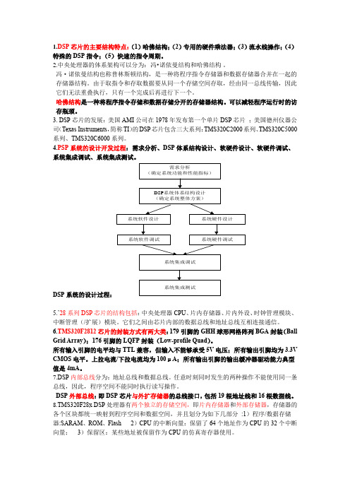
1.DSP芯片的主要结构特点:(1)哈佛结构;(2)专用的硬件乘法器;(3)流水线操作;(4)特殊的DSP指令;(5)快速的指令周期。
2.中央处理器的体系架构可以分为:冯•诺依曼结构和哈佛结构。
冯·诺依曼结构也称普林斯顿结构,是一种将程序指令存储器和数据存储器合并在一起的存储器结构。
由于取指令和存取数据要从同一个存储空间存取,经由同一总线传输,因此它们无法重叠执行,只有一个完成后再进行下一个。
哈佛结构是一种将程序指令存储和数据存储分开的存储器结构。
可以减轻程序运行时的访存瓶颈。
3. DSP芯片的发展:美国AMI公司在1978年发布第一个单片DSP芯片;美国德州仪器公司(Texas Instruments,简称TI)的DSP芯片包含三大系列:TMS320C2000系列、TMS320C5000系列、TMS320C6000系列。
4.PSP系统的设计开发过程:需求分析、DSP体系结构设计、软硬件设计、软硬件调试、系统集成调试、系统集成测试。
DSP5.’28系列DSP芯片的结构包括:中央处理器CPU、片内存储器、片内外设、时钟管理模块、中断管理(/扩展)模块。
它们之间由芯片内部的数据总线和地址总线互相连接通信。
6.TMS320F2812芯片的封装方式有两大类:179引脚的GHH球形网格阵列BGA封装(Ball Grid Array);176引脚的LQFP封装(Low-profile Quad)。
所有输入引脚的电平均与TTL兼容,但输入不能够承受5V电压;所有输出引脚均为3.3V CMOS电平。
上拉电流/下拉电流均为100μA;所有输出引脚的输出缓冲器驱动能力典型值是4mA。
7.DSP内部总线分为:地址总线和数据总线。
任意时刻同时发生的两种操作不能使用同一条总线,因此,程序空间不能同时执行读写操作。
DSP外部总线:即DSP芯片与外扩存储器的总线接口,包括19根地址线和16根数据线。
8.TMS320F28x DSP处理器有两个独立的存储空间,即片内存储器和外部存储器,存储器的各个区块都统一映射到程序空间和数据空间,并且划分为如下几部分:1)程序/数据存储器:SARAM、ROM、Flash 2)CPU的中断向量:保留了64个地址作为CPU的32个中断向量;3)保留区:某些地址被保留作为CPU的仿真寄存器使用。
dsp外文翻译

外文参考文献翻译英文题目 The Breadth and Depth of DSP 中文题目 DSP的广度和深度学院自动化与电气工程学院专业自动化姓名白学文学号 201108536指导教师王思明2015 年 04月 20日DSP的广度和深度数字信号处理是最强大的技术,将塑造二十一世纪的科学与工程之一。
革命性的变化已经在广泛的领域:通信,医疗成像,雷达和声纳,高保真音乐再现,石油勘探,仅举几例。
上述各领域已建立了深厚的DSP技术,用自己的算法,数学,和专门技术。
这种呼吸和深度的结合,使得它不可能为任何一个人掌握所有已开发的DSP技术。
DSP教育包含两个任务:学习一般适用于作为一个整体领域的概念,并学习您感兴趣的特定领域的专门技术。
本章开始描述DSP已在几个不同领域的戏剧性效果的数字信号处理的世界,我们的旅程。
革命已经开始。
1 DSP的根源独特的数据类型,它使用的信号,数字信号处理是区别于其他计算机科学领域。
在大多数情况下,这些信号源于感觉来自现实世界的数据:地震的震动,视觉图像,声波等DSP是数学,算法,并用来操纵这些信号的技术后,他们已被转换成数字形式。
这包括了各种目标,如:加强视觉图像识别和语音生成,存储和传输的数据压缩,等假设我们重视计算机模拟 - 数字转换器,并用它来获得一个现实世界的数据块。
DSP回答了这个问题:下一步怎么办?DSP的根是在20世纪60年代和70年代数字计算机时首次面世。
电脑是昂贵的,在这个时代,DSP是有限的,只有少数关键应用。
努力开拓,在四个关键领域:雷达和声纳,国家安全风险是石油勘探,可以大量资金;太空探索,其中的数据是不可替代的;和医疗成像,可节省生活。
20世纪80年代和90年代的个人电脑革命,引起新的应用DSP的爆炸。
而不是由军方和政府的需求动机,DSP的突然被带动的商业市场。
任何人士如认为他们可以使资金在迅速扩大的领域突然一个DSP供应商。
DSP的市民等产品达到:移动电话机,光盘播放器,电子语音邮件。
DSP滤波器中英文对照外文翻译文献

中英文对照外文翻译文献(文档含英文原文和中文翻译)译文:GA算法优化IIR滤波器的设计摘要本文提出了运用遗传算法(GA)来优化无限脉冲响应数字滤波器(IIR)的设计。
IIR滤波器本质上是一个递归响应的数字滤波器。
由于IIR 数字滤波器的表面误差通常是非线性的和多峰的,而全局优化技术需要避免局部最小值。
本文提出了启发式方式来设计IIR滤波器。
GA是组合优化问题中一种功能强大的全局优化算法,该论文发现IIR数字滤波器的最佳系数可以通过GA 优化。
该设计提出低通和高通IIR数字滤波器的设计,以提供过渡频带的估计值。
结果发现,所计算出的值比可用于过滤器的在MATLAB设计FDA工具更优化。
举个例子,采用的仿真结果表明在过渡带和均方误差(MSE)的改善。
零极点的位置也被提出来用来描述系统的的稳定性,以便将结果与模拟退火(SA)的方法相比较。
关键词:数字滤波器;无限冲激响应(IIR);遗传算法(GA);优化1.说明在过去的几十年中的数字信号处理(DSP)领域已经成长太重要的理论和技术。
在DSP中,有两个重要的类型系统。
第一类型的系统是执行信号滤波的时域,因此它被称为数字滤波器。
第二类型的系统提供的信号表示频域,被称为频谱分析仪。
数字滤波是DSP的最有力的工具之一。
数字滤波器能够性能规格,最好的同时也是极其困难的,而且不可能的是,先用模拟滤波器实现。
另外,数字滤波器的特性,可以很容易地在软件控制下发生变化。
数字滤波器被分类为有限持续时间脉冲响应(FIR)滤波器或无限持续时间脉冲响应(IIR)滤波器,这取决于该系统的脉冲响应的形式。
在FIR系统中,脉冲响应序列是有限的持续时间,即,它具有非零项的数量有限。
数字无限脉冲响应(IIR)滤波器通常可以提供比其等效有限脉冲响应(FIR)滤波器更好的性能和更少的计算成本,并已成为越来越感兴趣的目标。
但是,由于IIR滤波器的误差表面通常是非线性的,多式联运,传统的基于梯度的设计方法可以很容易地陷入错误的表面。
光伏发电逆变器毕业论文中英文资料外文翻译文献
光伏发电逆变器毕业论文中英文资料外文翻译文献附录:文献翻译TMS320LF2407, TMS320LF2406, TMS320LF2402TMS320LC2406, TMS320LC2404, MS320LC2402DSP CONTROLLERSThe TMS320LF240x and TMS320LC240x devices, new members of the ‘24x family of digital signal processor (DSP) controllers, are part of the C2000 platform of fixed-point DSPs. The ‘240x devices offer the enhanced TMS320 architectural design of the ‘C2xx core CPU for low-cost, low-power, high-performance processing capabilities. Several advanced peripherals, optimized for digital motor and motion control applications, have been integrated to provide a true single chip DSP controller. While code-compatible with the existing ‘24x DSP controller devices, the ‘240x offers increased processing performance (30 MIPS) and a higher level of peripheral integration. See the TMS320x240x device summary section for device-specific features.The ‘240x family offers an array of memory sizes and different peripherals tailored to meet the specific price/performance points required by various applications. Flash-based devices of up to 32K words offer a reprogrammable solution useful for:◆Applications requiring field programmability upgrades.◆Development and initial prototyping of applications that migrate to ROM-baseddevices.Flash devices and corresponding ROM devices are fully pin-to-pin compatible. Note that flash-based devices contain a 256-word boot ROM to facilitate in-circuit programming.All ‘240x devices offer at least one event manager module which has been optimized for digital motor control and power conversion applications. Capabilities of this module include centered- and/or edge-aligned PWM generation, programmable deadband to prevent shoot-through faults, and synchronized analog-to-digital conversion. Devices with dual event managers enable multiple motor and/or converter control with a single ‗240x DSP controller.The high performance, 10-bit analog-to-digital converter (ADC) has a minimum conversion time of 500 ns and offers up to 16 channels of analog input. The auto sequencing capability of the ADC allows a maximum of 16 conversions to take place in a single conversion session without any CPU overhead.A serial communications interface (SCI) is integrated on all devices to provide asynchronous communication to other devices in the system. For systems requiring additional communication interfaces; the ‘2407, ‘2406, and ‘2404 offer a 16-bit synchronous serial peripheral interface (SPI). The ‘2407 and ‘2406 offer a controller area network (CAN) communications module that meets 2.0B specifications. To maximize device flexibility, functional pins are also configurable as general purpose inputs/outputs (GPIO).To streamline development time, JTAG-compliant scan-based emulation has been integrated into all devices. This provides non-intrusive real-time capabilities required to debug digital control systems. A complete suite of code generation tools from C compilers to the industry-standard Code Composerdebugger supports this family. Numerous third party developers not only offer device-level development tools, but also system-level design and development support.PERIPHERALSThe integrated peripherals of the TMS320x240x are described in the following subsections:●Two event-manager modules (EV A, EVB)●Enhanced analog-to-digital converter (ADC) module●Controller area network (CAN) module●Serial communications interface (SCI) module●Serial peripheral interface (SPI) module●PLL-based clock module●Digital I/O and shared pin functions●External memory interfaces (‘LF2407 only)●Watchdog (WD) timer moduleEvent manager modules (EV A, EVB)The event-manager modules include general-purpose (GP) timers, full-compare/PWM units, capture units, and quadrature-encoder pulse (QEP) circuits. EV A‘s and EVB‘s timers, compare units, and capture units function identically. However, timer/unit names differ for EV A and EVB. Table 1 shows the module and signal names used. Table 1 shows the features and functionality available for the event-manager modules and highlights EV A nomenclature.Event managers A and B have identical peripheral register sets with EV A starting at 7400h and EVB starting at 7500h. The paragraphs in this section describe the function of GP timers, compare units, capture units, and QEPs using EV A nomenclature. These paragraphs are applicable to EVB with regard to function—however, module/signal names would differ.Table 1. Module and Signal Names for EV A and EVBEVENT MANAGER MODULESEV AMODULESIGNALEVBMODULESIGNALGP Timers Timer 1Timer 2T1PWM/T1CMPT2PWM/T2CMPTimer 3Timer 4T3PWM/T3CMPT4PWM/T4CMPCompare Units Compare 1Compare 2Compare 3PWM1/2PWM3/4PWM5/6Compare 4Compare 5Compare 6PWM7/8PWM9/10PWM11/12Capture Units Capture 1Capture 2Capture 3CAP1CAP2CAP3Capture 4Capture 5Capture 6CAP4CAP5CAP6QEP QEP1QEP2QEP1QEP2QEP3QEP4QEP3QEP4External Inputs DirectionExternalClockTDIRATCLKINADirectionExternal ClockTDIRBTCLKINBGeneral-purpose (GP) timersThere are two GP timers: The GP timer x (x = 1 or 2 for EV A; x = 3 or 4 for EVB) includes:● A 16-bit timer, up-/down-counter, TxCNT, for reads or writes● A 16-bit timer-compare register, TxCMPR (double-buffered with shadow register), forreads or writes● A 16-bit timer-period register, TxPR (double-buffered with shadow register), forreads or writes● A 16-bit timer-control register,TxCON, for reads or writes●Selectable internal or external input clocks● A programmable prescaler for internal or external clock inputs●Control and interrupt logic, for four maskable interrupts: underflow, overflow, timercompare, and period interrupts● A selectable direction input pin (TDIR) (to count up or down when directionalup-/down-count mode is selected)The GP timers can be operated independently or synchronized with each other. The compare register associated with each GP timer can be used for compare function and PWM-waveform generation. There are three continuous modes of operations for each GP timer in up- or up/down-counting operations. Internal or external input clocks with programmable prescaler are used for each GP timer. GP timers also provide the time base for the other event-manager submodules: GP timer 1 for all the compares and PWM circuits, GP timer 2/1 for the capture units and the quadrature-pulse counting operations. Double-buffering of the period and compare registers allows programmable change of the timer (PWM) period and the compare/PWM pulse width as needed.Full-compare unitsThere are three full-compare units on each event manager. These compare units use GP timer1 as the time base and generate six outputs for compare and PWM-waveform generation using programmable deadband circuit. The state of each of the six outputs is configured independently. The compare registers of the compare units are double-buffered, allowing programmable change of the compare/PWM pulse widths as needed.Programmable deadband generatorThe deadband generator circuit includes three 8-bit counters and an 8-bit compare register. Desired deadband values (from 0 to 24 µs) can be programmed into the compare register for the outputs of the three compare units. The deadband generation can be enabled/disabled for each compare unit output individually. The deadband-generator circuit produces two outputs (with orwithout deadband zone) for each compare unit output signal. The output states of the deadband generator are configurable and changeable as needed by way of the double-buffered ACTR register.PWM waveform generationUp to eight PWM waveforms (outputs) can be generated simultaneously by each event manager: three independent pairs (six outputs) by the three full-compare units with programmable deadbands, and two independent PWMs by the GP-timer compares.PWM characteristicsCharacteristics of the PWMs are as follows:●16-bit registers●Programmable deadband for the PWM output pairs, from 0 to 24 µs●Minimum deadband width of 50 ns●Change of the PWM carrier frequency for PWM frequency wobbling as needed●Change of the PWM pulse widths within and after each PWM period as needed●External-maskable power and drive-protection interrupts●Pulse-pattern-generator circuit, for programmable generation of asymmetric,symmetric, and four-space vector PWM waveforms●Minimized CPU overhead using auto-reload of the compare and period registersCapture unitThe capture unit provides a logging function for different events or transitions. The values of the GP timer 2 counter are captured and stored in the two-level-deep FIFO stacks when selected transitions are detected on capture input pins, CAPx (x = 1, 2, or 3 for EV A; and x = 4, 5, or 6 for EVB). The capture unit consists of three capture circuits.Capture units include the following features:●One 16-bit capture control register, CAPCON (R/W)●One 16-bit capture FIFO status register, CAPFIFO (eight MSBs are read-only, eightLSBs are write-only)●Selection of GP timer 2 as the time base●Three 16-bit 2-level-deep FIFO stacks, one for each capture unit●Three Schmitt-triggered capture input pins (CAP1, CAP2, and CAP3)—one input pinper capture unit. [All inputs are synchronized with the device (CPU) clock. In order fora transition to be captured, the input must hold at its current level to meet two risingedges of the device clock. The input pins CAP1 and CAP2 can also be used as QEPinputs to the QEP circuit.]●User-specified transition (rising edge, falling edge, or both edges) detection●Three maskable interrupt flags, one for each capture unitEnhanced analog-to-digital converter (ADC) moduleA simplified functional block diagram of the ADC module is shown in Figure 1. The ADC module consists of a 10-bit ADC with a built-in sample-and-hold (S/H) circuit. Functions of the ADC module include:●10-bit ADC core with built-in S/H●Fast conversion time (S/H + Conversion) of 500 ns●16-channel, muxed inputs●Autosequencing capability provides up to 16 ―autoconversions‖ in a single session.Each conversion can be programmed to select any 1 of 16 input channels●Sequencer can be operated as two independent 8-state sequencers or as one large16-state sequencer (i.e., two cascaded 8-state sequencers)●Sixteen result registers (individually addressable) to store conversion values●Multiple triggers as sources for the start-of-conversion (SOC) sequence✧S/W – software immediate start✧EV A – Event manager A (multiple event sources within EV A)✧EVB – Event manager B (multiple event sources within EVB)✧Ext – External pin (ADCSOC)●Flexible interrupt control allows interrupt request on every end of sequence (EOS) orevery other EOS●Sequencer can operate in ―start/stop‖ mode, allowing multiple ―time-sequencedtriggers‖ to synchronize conv ersions●EV A and EVB triggers can operate independently in dual-sequencer mode●Sample-and-hold (S/H) acquisition time window has separate prescale control●Built-in calibration mode●Built-in self-test modeThe ADC module in the ‘240x has been enhanced to pro vide flexible interface to event managers A and B. The ADC interface is built around a fast, 10-bit ADC module with total conversion time of 500 ns (S/H + conversion). The ADC module has 16 channels, configurable as two independent 8-channel modules to service event managers A and B. The two independent 8-channel modules can be cascaded to form a 16-channel module. Figure 2 shows the block diagram of the ‘240x ADC module.The two 8-channel modules have the capability to autosequence a series of conversions,each module has the choice of selecting any one of the respective eight channels available through an analog mux. In the cascaded mode, the autosequencer functions as a single 16-channel sequencer. On each sequencer, once the conversion is complete, the selected channel value is stored in its respective RESULT register. Autosequencing allows the system to convert the same channel multiple times, allowing the user to perform oversampling algorithms. This gives increased resolution over traditional single-sampled conversion results.Figure 2. Block Diagram of the ‘240x ADC ModuleFrom TMS320LF2407, TMS320LF2406, TMS320LF2402TMS320LC2406, TMS320LC2404, MS320LC2402数字信号处理控制器TMS320LF240x和TMS320LC240x系列芯片作为’24x系列DSP控制器的新成员,是C2000平台下的一种定点DSP芯片。
电力系统继电保护毕业论文中英文资料外文翻译文献

电力系统继电保护论文中英文资料Relay protection development present situation[Abstract ]reviewed our country electrical power system relay protection technological devil orpiment process,has outlined the microcomputer relay protection technology achievement, pro posed the future relay protection technological development tendency will be: Computerizes, n networked,protects, the control,the survey,the data communication integration and the artificial I intellectualization.[Key word ]relay protection present situation development,relay protections future development1 relay protection development present situationThe electrical power system rapid development to the relay protection proposed unceasingly t he new request,the electronic technology,computer technology and the communication rapid development unceasingly has poured into the new vigor for the relay protection technology de velopment,therefore,the relay protection technology is advantageous, has completed the deve lopment 4 historical stage in more than 40 years time。
基于DSP的视频采集与传输外文翻译
淮阴工学院毕业设计(论文)外文资料翻译学院:计算机工程学院专业:通信工程(多媒体)姓名:韩晓晓学号:1101312235外文出处:CollegeofInformationandCommunication Engineering,TianjinPolytechnicUniversity Tianjin 300160, CHN附件: 1.外文资料翻译译文;2.外文原文。
附件1:外文资料翻译译文基于DSP的嵌入式远程视频监控系统设计摘要:本系统提出的是一套基于TMS320DM642的嵌入式远程视频监控系统设计,利用DM642为核心的数据处理,该系统是由视频采集、视频处理和通信模块组成,提供一个实现迷你驱动模块的DSP / BIOS的集成开发环境,并在应用程序层实现一项常见的任务模块。
该系统实现整个模拟视频信号采集,H.264视频编码和网络传输的功能, 它提供了通用连接未来发展并具有良好的灵活性和可扩展性,系统采用了模块化设计和整体开发的编程方法来提高系统的效率。
关键词:DM642;远程监控系统;H.264;视频采集;网络界面1 导言随着科学技术的迅速发展,网络不仅提供了简单的文本、图片和声音文件功能,而且开始提供各种音频和视频来丰富人们的生活,与此同时,监控系统已经从传统发展成智能化,多媒体化和网络化。
传统的监控系统只提供视频监控,多媒体监控系统提供了音频监控,极大地丰富监控的内容,提供实时的网络服务和连续音频流是很有必要的,视频传输应该满足远程实时监控的要求。
TI公司在2003年提供的TMS320DM642 是一款拥有专用视频接口的性能很高的DSP芯片,它有强大的DSP内核和先进的总线结构。
它的频率范围是从480MHZ到720MHZ,在600 MH z主时钟频率数字处理能力可以达到4800 mips,DM642集成各种使视频和图片更方便于实际应用发展的外设。
可以对它进行配置三个视频端口,提供无缝的视频输入接口、视频输出和输入符号流,包括BT. 656, HDTVY/ C,RGB 和MPEG-2输入流,为了基于DM642视频编码器的发展,视频输入只需要一个视频采集芯片,不需要外部的逻辑控制电路和输入/输出缓存器,因此,硬件系统设计及其操作比其他系统更稳定。
- 1、下载文档前请自行甄别文档内容的完整性,平台不提供额外的编辑、内容补充、找答案等附加服务。
- 2、"仅部分预览"的文档,不可在线预览部分如存在完整性等问题,可反馈申请退款(可完整预览的文档不适用该条件!)。
- 3、如文档侵犯您的权益,请联系客服反馈,我们会尽快为您处理(人工客服工作时间:9:00-18:30)。
A DSP-based signal processing method and system forCMFQi-Li Hou a ,Ke-Jun Xu a ,b ,⇑,Min Fang a ,Wen-Jun Xiong a ,Cui Liu aa School of Electrical and Automation Engineering,Hefei University of Technology,Hefei 230009,China bEngineering Technology Research Center of Industrial Automation,Hefei 230009,Chinaa r t i c l e i n f o Article history:Received 22December 2012Accepted 4March 2013Available online 25March 2013Keywords:Coriolis mass flowmeter Signal processing method Adaptive lattice notch filterDTFT algorithm considering negative frequency DSPa b s t r a c tA set of digital signal processing method is formed by combining a digital band-pass filter,an adaptive lattice notch filter and the DTFT algorithm considering negative frequency con-tribution for processing the signals of Coriolis mass flowmeter.A digital Coriolis mass flow transmitter is developed with a DSP chip to realize the signal processing approach.Some effective measures are proposed to ensure high accuracy and real time of this approach in the implementation.Simulations,electrical signal tests and water flowrate calibrations are conducted to validate the performances of the method and the system.Ó2013Elsevier Ltd.All rights reserved.1.IntroductionCoriolis mass flowmeter (CMF)is widely used in many industries,such as food and beverages,chemical and phar-maceuticals in oil and gas because it can measure the true mass flowrate directly and obtain the fluid density simul-taneously.The time difference between the output signals of two velocity sensors installed in vibrating flow tubes is detected to reflect the mass flowrate,and the vibrating fre-quency is calculated to express the fluid density.Tradi-tional analog processing method is easily subject to noise interference and has the low measurement accuracy when measuring small flowrate [1].Over the past decade,digital signal processing methods have been applied to the signal processing of CMF.These methods mainly include discrete Fourier transform (DFT),phase-locked loop (PLL),digital zero-crossing,adaptive line enhancer (ALE),sliding Goertzel,discrete-time Fourier transform (DTFT),etc.DFT was used to process the sensor output signals of CMF [2–7].Henry et al.found that Fourier-based technique was very precise [4].This method has good resistance to higher harmonics.Freeman utilized digital phase locked loop to process the signals of CMF [8],and Xu also studied on this method [9].Zheng et al.employed a digital zero-crossing method to calculate the frequency and phase difference of the signals of CMF [10].Derby et al.introduced ALE into the signal processing of CMF [11–14].Signals are firstly fil-tered and decimated.Then the frequency of the signals is calculated through ALE to enhance the signals.The phase difference between the signals is obtained using Fourier analysis or Goertzel Fourier transform.Xu and Ni et al.improved the above algorithm [15,16].An adaptive Funnel filter (AFF)or a lattice notch filter was adopted to track the signal frequency because of these filters having good per-formance in tracking accuracy and speed.On this basis,a signal model whose frequency,amplitude and phase were in the pattern of time-varying was proposed to describe the sensor output signals.The phase difference was calcu-lated by the sliding Goertzel algorithm [16].Tu utilized discrete-time Fourier transform (DTFT)considering nega-tive frequency contribution to obtain the phase difference through calculating the Fourier coefficients at the specific frequency,and is not affected by the non-integer period sampling [17].The simulation results for steady signals showed a better performance of DTFT than that of SGA.0263-2241/$-see front matter Ó2013Elsevier Ltd.All rights reserved./10.1016/j.measurement.2013.03.010Corresponding author at:School of Electrical and Automation Engi-neering,Hefei University of Technology,Hefei 230009,China.Tel.:+8655162901412.E-mail address:dsplab@ (K.-J.Xu).In this paper,not only the DTFT algorithm considering negative frequency is utilized to calculate the phase differ-ence between two velocity sensors installed in theflow tubes of Coriolis massflowmeter,but also a digital band-passfilter and an adaptive lattice notchfilter are adopted to remove noise and calculate the frequency of the velocity sensor before performing the phase difference computa-tion.Thus a complete signal processing approach is formed for Coriolis massflowmeter by combining three kinds of algorithms.Furthermore some effective measures are pro-posed to ensure the calculation precision and real-time of this approach in the implementation of DSP-based system, which is very important for Coriolis massflowmeter due to its requirements of high accuracy.Finally electrical signal tests and waterflowrate calibrations were conducted to evaluate the ability of anti-interference,the stability of meter zero-point,measurement accuracy and turn-down ratio.2.Signal processing method2.1.Band-passfilterThere is a variety of noise in industrialfields,such as fluidflow noise,power supply noise,and pipe vibration noise,which influence the signals of CMF.Therefore a kind of IIR band-typefilter with the structure of notchfilter is employed to deal with the signals of CMF for removing the effect of noise.The transfer function of thefilter isHðzÞ¼1þq1a zÀ1þq21zÀ21þq2a zÀ1þq22zÀ2ð1Þwhere0<q1<1;0<q2<1;a=À2cos x,and x is the cen-ter frequency which is needed to be enhanced or elimi-nated.Both z=e j x=cos x+j sin x and a=À2cos x are substituted into Eq.(1),the gain of thefilter at x isj HðzÞj¼ffiffiffiffiffiffiffiffiffiffiffiffiffiffiffiffiffiffiffiffiffiffiffiffiffiffiffiffiffiffiffiffiffiffiffiffiffiffiffiffiffiffiffiffiffiffiffiffiffiffiffiffiffiffiffiffiffiffiffiffiffiffiffiffiffiffiffiffiffiffiffið1Àq1Þ2½ð1þq1Þ2À4q1cos2xð1À2Þ½ð1þ2ÞÀ42cos2sð2Þwhen q1%1,q2%1,and x is not in the vicinity of0,p and 2p,Eq.(2)can be simplified asj HðzÞj%1Àq11Àq2ð3ÞIt is obvious that when q1>q2,the signal at x will be eliminated;when q1<q2,the signal at x will be enhanced. The trap depth of thefilter depends on q1and q2mainly, and is affected by x rarely.The trap width of thefilter depends on q1and q2,and mainly on q2.When thefilter is designed,q1isfirstlyfixed, and q2is adjusted to change the trap width of thefilter. The more close q2is to1,the narrower the width will be. Then q1is adjusted to change the trap depth of thefilter. Here,set q1<q2to construct a band-passfilter for enhanc-ing the sensor signals.Thisfilter with narrow pass-band width is suitable to process the signals of CMF because the signal frequency of CMF is almostfixed,e.g.for the U-tubes type of CMF,the frequency difference between empty and full tubes is less than10Hz.ttice adaptive notchfilterThe transfer function of lattice adaptive notchfilter (ANF)can be expressed as:HðzÞ¼1þk0ð1þk1ÞzÀ1þk1zÀ21þa0ð1þa1ÞzÀ1þa1zÀ2ð4ÞSuppose a0=k0and a1=q k1to construct a notchfilter. At the same time,the zeros are constrained on the unit cir-cle so as to reduce the amount of computation,that is, k1=1.Then Eq.(4)can be expressed asHðzÞ¼1þ2k0zÀ1þzÀ21þk0ð1þqÞzÀ1þq zÀ2ð5ÞSince the parameter q determines the band width of the notchfilter,the value of q is set as a slightly large value at the beginning to capture the frequency easily,and then is reduced slowly to ensure the frequency tracking accuracy. The simulation result shows that when thefinal value of q is set as0.99,it can obtain good calculation accuracy and track the variation of signal frequency simultaneously. The iterative process can be expressed as Eq.(6).qðnÞ¼0:99À0:195Â0:99ðnÀ1Þð6ÞThe estimation of signal frequency is^xðnÞ¼arccosðÀk0ðnÞÞð7ÞThe enhanced signal of raw signal is^yðnÞ¼yðnÞÀxðnÞð8Þwhere^yðnÞis the enhanced signal,y(n)is the raw signal, and x(n)is the output of the ANF,that is noise.Compared with the direct ANF,the lattice ANF only needs to adjust one parameter,so the amount of calcula-tion is greatly reduced.At the same time,the lattice ANF has shorter convergence process and can obtain steadier result.By adjusting the value of q,it can track signal well with high precision.2.3.DTFT considering negative frequency contributionTwo channel sampled sequences in sine wave of the same frequency can be expressed ass1ðnÞ¼A1cosðx nþh1Þs2ðnÞ¼A2cosðx nþh2Þð9Þwhere A1and A2are amplitudes;h1and h2are initial phases;x=2p f/f s,f is signal frequency,and f s is sampling frequency.Suppose^x is the estimated value of x,then the DTFT of s1(n)isS1Nð^xÞ¼X NÀ1n¼0A1cosðx nþh1ÞÁeÀj^x n¼X NÀ1n¼0A1½e jðx nþh1ÞþeÀjðx nþh1Þ ÁeÀj^x nð10ÞQ.-L.Hou et al./Measurement46(2013)2184–21922185Considering the negative frequency contribution,we haveS1Nð^xÞ¼A12e j h1X NÀ1n¼0e jðxÀ^xÞnþA12eÀj h1X NÀ1n¼0eÀjðxþ^xÞnð11ÞBy deducing,the computation equation of phase differ-ence for two channel signals isD h¼arctanm1ðtan u2Àtan u1Þm2þm3ðtan u1þtan u2Þþm4tan u1tan u2ð12Þ2.4.Simulation results of algorithm2.4.1.Simulations for anti-interference of algorithmThe sensor signals in the industrialfield are collected toperform the spectrum analysis.The results show that the main noise is the second harmonic offlow-tube natural frequency.There are also random noise and the noise near-by theflow-tube natural frequency.Therefore a signal model is built as shown in Eq.(13),and the signal is gener-ated using Matlab language for simulation.x¼1:0Ásinð2ÁpÁf=f sÁnÞþnoise1þnoise2þnoise3ð13Þwhere f is187.8Hz which is the natural frequency of CNG050type Coriolis massflowmeter made by a US com-pany:Emerson Process Management;f s is the sampling frequency,2kHz;the number of sampling points is6000;noise1is random noise,noise2is the second harmonic, noise3is the noise whose frequencies are between 150Hz and250Hz.The amplitudes of noise are set as 0.02,0.05and0.02in order to make the SNR be about 25dB.This signal isfiltered by Eq.(1),and the spectrum analysis of the raw andfiltered signal are shown in Figs. 1and2,respectively.The simulation results indicate that thefilter can eliminate the effect of noise greatly.2.4.2.Simulations for processing accuracy of algorithmThe signal contaminated by noise is preprocessed by thefilter mentioned above,and then its frequency is calcu-Table1Simulation results of DTFT.Theoretic value of phasedifference(°)Estimated value of phasedifference(°)Relativeerror(%)Theoretic value of phasedifference(°)Estimated value of phasedifference(°)Relativeerror(%)0.10.099986À0.0130.20.199985À0.0070.30.299986À0.0050.40.399958À0.0100.50.5000510.0100.60.599958À0.0060.70.699915À0.0120.80.799905À0.0120.90.9000490.005 1.0 1.0000740.0071.3 1.299878À0.009 1.6 1.599852À0.0092.0 2.0002320.0123.0 2.999703À0.010 2186Q.-L.Hou et al./Measurement46(2013)2184–2192lated by the lattice ANF.The simulation result of frequency calculation is shown in Fig.3.After1000points,the lattice ANF reaches convergence,the relative error of frequency calculation is smaller than0.002%.According to the frequency value the phase difference of two channelfiltered signals is obtained by the DTFT algorithm.In order to eliminate the effect of convergence process of the lattice ANF,the data after2000are calcu-lated by the DTFT algorithm.The means and relative errors are listed in Table1.As shown in Table1,when the values of the phase dif-ference vary from0.1°to3.0°,the calculation accuracy is better than0.02%.3.Development of transmitterIt is necessary to select a kind of micro-processor with high data processing ability and abundant peripherals for implementing the various functions of Coriolis massflow transmitter,such as calculation,control and interfaces.Therefore TMS320F28335,a DSP chip made by TI Company is chosen to develop a Coriolis massflow transmitter.3.1.Transmitter hardwareA block diagram of the transmitter hardware is shown in Fig.4.It consists of an analog drive system,analog signal amplifying andfiltering circuits,three24-bit analog-to-digital converters,an external static random access memory,an electrical erasable programmable read-only memory,a liquid crystal display,a keyboard,a digital-to-analog converter,a voltage-to-current circuit,a pulse outputting circuit.3.2.Transmitter softwareA block diagram of the transmitter software is shown in Fig.5.It is designed with modularized scheme,and mainly consists of a main monitoring program,an initialization module,an interrupt module,an EEPROM module,awatchQ.-L.Hou et al./Measurement46(2013)2184–21922187dog module,an algorithm module,an outputting module,a man–machine interface module.All these subprograms are called by the main monitoring program.After powered up,the main monitoring program calls the initialization module,and then starts conversation of ADC to collect the sensor signals.When certain length of new data has been sampled,DSP begins to call the algo-rithm module to calculate the massflowrate continuously. During this procedure,DSP also deals with the LCD display and keyboard input.In the cputimer0interrupt service subprogram,DSP obtains the total massflowrate by accu-mulating the current instantaneous massflowrate,and outputs the pulse and4–20mA DC current signals which stand for the massflowrate.Theflow chart of the transmit-ter software is shown in Fig.6.3.3.Key technologies in implementation(1)Digital signal processing methods have the charac-teristic of anti-interference ability and high accu-racy,but needs to deal with large amounts of data.Therefore it is very important to reduce the CPUresource occupied by data transmission for ensuringthe real-time realization of the algorithms.ADCs run at the high sampling frequency.It will not sat-isfy the real-time requirement if DSP reads the sampled data from the ADCs point by ing the direct memory access module(DMA)and the multichannel buffered serial port module(McBSP),the data transmission from ADCs to DSP will be completed without using the CPU resource. The implementation steps are as follows.Both McBSPA and McBSPB are configured as SPI function to communicate with ADCs,the trigger events of DMA channels1and2are selected as the receive events of McBSPA and McBSPB,the source address of DMA channels1and2are set as the data receive register(DRR)address of McBSPA and McBSPB,and the destination address is configured as the user defined buffer address of BufferL and BufferR.After the above con-figurations are completed,the conversion results of two ADCs are stored automatically in BufferL and BufferR from DRR register by DMA.When the buffers are full,DMA will trigger an interrupt to inform CPU.Note that in initializa-tion process,DMA must be initializedfirst to be ready to transmit,and then McBSP is initialized.This ensures data from two ADCs will be read simultaneously.(2)Thefiltering function of lattice ANF is used properlyto enhance the anti-interference ability of thealgorithm.The lattice ANF has the ability offiltering signals.The filtered signals are enhanced after the raw signal through the lattice ANF.If two lattice ANFs are used to deal with two sensor signals separately,a phase difference will be generated because the parameters of two ANFs are not the same,which will cause the measurement error.Hence one ANF is adopted to process two sensor signals.(3)It is very important how to achieve the high compu-tation accuracy during the algorithm implementa-tion by DSP.Some measures are taken as follows:1)The32-bitfloat type variable cannot ensure highprecision due to its low LSB,so the64-bit doubletype variable is utilized in DSP programs.2)In DSP programs the calculation of sin and cos can beimplemented by calling the function library of DSP.But the calculation results of the function library pos-sess only thefloat-point type precision,and the calcu-lation errors will become large with the value ofvariable increasing,which does not meet the require-ment of the processing accuracy of CMF.We tried toemploy the series approximation method for realizingthe calculation of sin and cos,and developed the pro-gram by ourselves.Its real-time performance,how-ever,is poor,and does not meet the need of CMF.Forsolving this problem,the values of variable are normal-ized to the range between0to2p beforesin/cos 2188Q.-L.Hou et al./Measurement46(2013)2184–2192calculation to ensure the computation accuracy,whichis very important especially when measuring the smallphase difference.For example,the true value ofsin(1234.5678)is0.07803344920002,DSP will obtain0.0780842if calculated directly.Consider that1234.5678equals2pÂ196+3.06347979280122,soDSP calculates sin(3.06347979280122)instead ofsin(1234.5678),and obtains0.0780333which is veryclose to the true value.3)The signal frequency value is needed when perform-ing DTFT algorithm.The simulation results show thesignal frequency value provided for DTFT algorithmshould befixed so as to ensure the stability of calcu-lation results.Under the condition of not reducingprecision,therefore,the frequency obtained by lat-tice ANF will not be refreshed until the relative errorbetween the new value and the old value is largerthan0.003%.4.Experiments of transmitterAfter the transmitter had been developed,algorithm execution time tests,electrical signal tests and water flowrate calibrations were performed to validate its perfor-mance of real time,ability of anti-interference,stability of the meter zero-point,and measurement accuracy of small flowrate.4.1.Algorithm execution time testsThe clock frequency of TMS320F28335is150MHz.The sensor signals are collected at the sampling frequency of 2kHz.For every sampling data,the total processing time of the transmitter is about420l s,including digitalfilter, lattice ANF,DTFT,flowrate calculation and LCD refreshing. Therefore,the whole approach can be realized in real time.4.2.Electrical signal testsA signal generator,Fluke282,was used to provide the signals for the electrical signal tests.Firstly,two channel sinusoidal signals with the same frequency of187.8Hz and the certain phase differences were built by MATLAB. The signals were mixed with some kinds of noise,such as the second harmonic,random noise,and the noise nearbyTable2Testing results of electrical signals.Theoretic value of phase difference(°)Estimated value of phasedifference(°)Relativeerror(%)Theoretic value of phasedifference(°)Estimated value of phasedifference(°)Relativeerror(%)0.1080.1079649À0.03250.1800.1799398À0.0335 0.2880.2879892À0.00380.3960.39600090.0002 0.4680.4679492À0.01090.5760.5759822À0.0031 0.6840.68404710.00690.7920.7919790À0.00270.8280.8275430À0.05520.9000.8999695À0.00341.008 1.00800940.0009 1.332 1.3319460À0.00412.016 2.01600600.00033.024 3.0239918À0.0003Q.-L.Hou et al./Measurement46(2013)2184–219221892190Q.-L.Hou et al./Measurement46(2013)2184–2192Table3Calibration results.Flowrate(kg/min)Theoretic totalflowrate(kg)Estimated totalflowrate(kg)Relative error(%)Mean relative error(%)Repeatability(%)LZLG-8-30flow tube(10mm)3116.30616.3160.06216.55916.558À0.0010.0180.0416.64516.644À0.0061416.16016.1700.05916.15616.1660.0630.0710.0216.11216.1260.090616.22616.2320.03716.16916.1710.0100.0310.0216.12416.1310.046215.64315.642À0.006À0.0390.0415.79615.788À0.04615.80315.792À0.065LZLG-8-500flow tube(40mm)489246.906246.9100.002246.445246.426À0.0080.0010.01246.005246.0260.009248217.577217.6260.023218.317218.3740.0260.0260.00219.979220.0440.03099214.794214.8300.017215.414215.4480.0160.0190.01215.554215.6080.02538211.831211.8380.003212.011211.972À0.018À0.0040.01212.191212.1960.00227208.968208.964À0.002209.208209.170À0.018À0.0220.03208.988208.894À0.045LZLG1200USflow tube(50mm)248228.669228.550À0.052230.010229.964À0.020À0.0450.02230.431230.288À0.06297220.621220.472À0.067221.422221.330À0.041À0.0360.04218.739218.738À0.00047216.296216.274À0.010216.316216.246À0.033À0.0190.01216.677216.646À0.01425210.671210.510À0.076210.571210.450À0.057À0.0540.03210.771210.708À0.03012204.725204.706À0.009204.244204.204À0.020À0.0180.01203.624203.572À0.025US3000/lflow tube(80mm)2075730.276730.3800.0140.0210.04 748.293748.7200.057745.140745.080À0.0081516760.205759.960À0.032À0.0100.02 756.852756.9200.009755.601755.540À0.008635727.022726.620À0.055À0.0430.01 729.324729.040À0.039731.076730.820À0.035202728.524728.460À0.009À0.0150.02 728.573728.320À0.035726.221726.200À0.003the signal frequency.The SNR of the mixed signals was between18dB and20dB.Then,the signals were loaded to Fluke282.Fluke282outputted these signals as the ana-log signal form.The transmitter collected these signals and calculated their phase differences.The testing results are shown in Table2.The computation accuracy of the phase difference is better than0.06%when the phase difference varies from0.108°to3.024°.4.3.Waterflowrate calibrationsThe transmitter was connected with the primary instru-ments made by Taiyuan Flowmeter Engineering Co.,Ltd.in Taiyuan city,China,to construct the digital Coriolis mass flowmeters with different diameter tubes.The sampling frequency of the transmitter is2kHz.After100points of data have been sampled,DSP begins calculation.The total processing time for100points of data is about42ms, including algorithm operation,LCD displaying,pulse and 4–20mA current outputting.The waterflowrate calibra-tions were conducted to evaluate their ability of anti-inter-ference,stability of the meter zero-point,measurement accuracy and turn-down ratio.4.3.1.Examining the ability of anti-interferenceThe Coriolis massflowmeter with the natural frequency of92.4Hz was installed in pipelines,and would be affected by environment noise produced by equipments,such as motors,pumps and valves.The sensor signals of the meter were collected and analyzed by spectrum method.The re-sults indicate that the main noise is the second harmonic (183.2Hz)of theflow tube vibration frequency,which is shown in Fig.7.Therefore thefilter designed above is used as a pre-processing to eliminate this noise.Thefiltered sig-nal is analyzed by spectrum,and is shown in -paring Fig.7with Fig.8,it is obvious that the second harmonic is almost removed by thefilter.4.3.2.Evaluating the stability of meter zero-pointThe Coriolis massflowmeter wasfixed in the pipe and itsflow tubes werefilled with water.The valves of both downstream and upstream of the pipe were closed so as to stop theflow of the water in the pipe.The transmitter collected two channel sensor signals and calculated their phase difference as the meter zero-point.The values of the meter zero-point were recorded every15s.The test of the meter zero-point lasted10h and the results are shown in Fig.9.The test results indicate that there is no zero-point drift after long-time running and the resultfluctuates within a small range between0.0005°and0.0007°.The stability of the zero-point data indicates that both the primary meter including the sensors andflow tubes and the transmitter can meet the experimental requirements.Having good characteristic of the meter zero-point is a necessary condi-tion for measuring smallflowrate accurately.4.3.3.Calibrating the measurement accuracy and turn-down ratioThe waterflowrate calibrations were conducted with the static weighing method according to China national industrial standards.Firstly,the valves were closed,and the zero-point of the meter was calibrated.Then the valves were opened,the upstream valve was fully opened,and the flowrate was changed by changing the opening degree of the downstream valve.The meter measured the massflow-rate and outputted the pulse signal.When the calibration started,the calibration device began to count the pulse numbers and a switcher acted simultaneously to let the fluid(water)flow to a tank to be weighed.When the cali-bration ended,the calibration device stopped counting the pulse and the switcher acted to let thefluidflow out through other pipeline.By comparing the pulse numbers with the weight of thefluid in the tank,the relative error can be obtained.Everyflowrate was tested3times to ob-tain the repeatability.The precision of the calibration rig is0.05%.The calibration results of Coriolis massflowmeters with 10mm,40mm,50mm and80mm diameterflow tubes are listed in Table3.The repeatability of all meters is better than0.05%.For Coriolis massflowmeter with10mm diameterflow tube, the measurement accuracy is better than0.09%when the turn-down ratio is15:1.For coriolis massflowmeter with the40mm diameterflow tube,the measurement accuracy is better than0.05%when the turn-down ratio is18:1.For Coriolis massflowmeter with50mm diameterflow tube, the measurement accuracy is better than0.08%when the turn-down ratio is20:1.For coriolis massflowmeter with the80mm diameterflow tube,the measurement accuracy is better than0.08%when the turn-down ratio is19:1. 5.Conclusions(1)The digital band-passfilter,adaptive notchfilter andDTFT algorithm considering negative frequency con-tribution are combined to construct a complete sig-nal processing method in order to eliminate noise,calculate the frequency and obtain the phasedifference for CMF.This method possesses shortconvergence,high accuracy and good ability ofanti-interference.(2)The digital transmitter is developed with DSP chip torealize the algorithms.Some effective measures aretaken to ensure the real-time performance and highprocessing accuracy of the algorithms,such asTable3(continued)Flowrate(kg/min)Theoretic totalflowrate(kg)Estimated totalflowrate(kg)Relative error(%)Mean relative error(%)Repeatability(%)106724.370724.4200.0070.0390.04722.068722.3200.035717.964718.5000.075Q.-L.Hou et al./Measurement46(2013)2184–21922191employing DMA and McBSP to complete datatransmission,adopting one lattice ANF to enhancesignals and using64-bit double type variables incalculation.(3)The waterflowrate calibrations are performed andexperimental results show that the transmitter hashigh measurement precision and wide turn-downratio.References[1]Yang Jiang.A novel method of measuring phase deviation signal forCoriolis massflowmeter,in:Proceedings of the5th World Congress on,Intelligent Control and Automation,June2004,pp.3705–3708.[2]P.Romano,Coriolis massflow rate meter having a substantiallyincreased noise immunity,U.S Patent4934196,June19,1990. [3]M.P.Henry,D.W.Clarke,J.H.Vignos,Digitalflowmeter,U.S Patent2002/0038186A1,March28,2002.[4]M.P.Henry,D.W.Clarke,N.Archer,et al.,A self-validating digitalCoriolis mass-flow meter:an overview,Control Engineering Practice 8(5)(2000)487–506.[5]M.Zamora,M.P.Henry,An FPGA implementation of a digital Coriolismassflow metering drive system,IEEE Transactions on Industrial Electronics55(7)(Apr.2008)2820–2831.[6]M.Tombs,M.Henry,F.Zhou,et al.,High precision Coriolis massflowmeasurement applied to small volume proving,Flow Measurement and Instrumentation17(6)(2006)371–382.[7]Kun Chen,De-Zhi Zheng,Shang-Chun Fan,et al,Novel Coriolis massflowmeter signal processing algorithms based on DFT and digitalcorrelation,in:2010IEEE Symposium on Industrial Electronics and Applications(ISIEA2010),October2010,pp.56–60.[8]B.S.Freeman,N.C.Ashevillc,Digital phase locked loop signalprocessing for Coriolis massflowmeter,U.S.Patent5804741, September8,1998.[9]Ke-Jun Xu,Wen-Fu Xu,The signal processing method of Coriolismassflowmeter based on a digital phase locked loop,Acta Metrologica Sinica24(2)(2003)122–128.[10]De-Zhi Zheng,Shang-Chun Fan,Wei-Wei Xing,The novel method ofphase difference detection in Coriolis massflowmeter,Chinese Journal of Scientific Instrument26(5)(2005)441–443.[11]H.V.Derby,T.Bose,S.Rajian,Method and apparatus for adaptive lineenhancement in Coriolis massflowmeter measurement,U.S Patent 5555190,September10,1996.[12]P.A.Regalia,An improved lattice-based adaptive IIR notchfilter,IEEETransactions on Signal Processing39(9)(Sep.1991)2124–2128. [13]N.I.Cho,S.U.Lee,Tracking analysis of an adaptive lattice notchfilter,IEEE Transactions on Circuits and Systems42(3)(1995)186–195.[14]N.I.Cho,S.U.Lee,On the adaptive lattice notchfilter for the detectionof sinusoids,IEEE Transactions on Circuits and System40(7)(1993) 405–416.[15]Ke-Jun Xu,Wen-Fu Xu,A signal processing method based on AFF andSGA for Coriolis massflowmeters,Acta Metrologica Sinica28(1) (Jan.2007)48–51.[16]Ke-Jun Xu,Wei-Ni,Zhi-Yuan Chen,A signal processing method forCoriolis massflowmeter based on timer-varying signal model and lattice notchfilter,Chinese Journal of Scientific Instrument27(6) (2006)596–601.[17]Ya-Qing Tu,Hai-Tao Zhang,Method for CMF signal processing basedon the recursive DTFT algorithm with negative frequency contribution,IEEE Transactions on Instrumentation and Measurement57(11)(2008)2647–2654.2192Q.-L.Hou et al./Measurement46(2013)2184–2192。