SK239说明书
SK-239BC常见问题

客服常规机型常见问题如下:1.SK-239B/C主机不能编程及不能正常工作:A、主机首先要处于编程状态下,主板里面的拨动开关一定要处于“SQ”状态。
B、SK-239B/C的负载最大范围在1A之内,正常只能接有线探头、警号、烟感探测器、对射、紧急按键、振动传感器等负载的总和,如所接的负载量超过主机带载范围必需配置外接电源,这样更好的保护主机的正常使用。
SK-968C的负载最大范围在350mA之内C、编程之后须按“确认”键,所设置的内容才能生效。
2.如何恢复出厂设置:指令地址31栏输入1234按确认键主机发出BB-BB四声响,主机面板的指示灯逐个闪烁,如早期07年之前使用的主机则使用指令地址31栏输入239*按确认键主机发出BB-BB四声响即可。
3.新买的遥控器不能控制主机:需在指令地址50栏重新学习对码,详见说明书第21页遥控器学习对码操作。
4.无线门磁、无线探头如何跟主机学习对码:在指令地址51栏对码学习,详见说明书第21页。
5.如何删除及修改接警电话号码:A、在编程状态下(主板拨动开关处于SQ状态),如删除第1组报警电话号码:复位+电话+01+确认(显示屏【01】138********)+#+确认。
B、在编程状态下(主板拨动开关处于SQ状态),如修改第1组报警电话号码:复位+电话+01+确认(显示屏【01】138********)+(输入新的电话号码)+确认。
注:以此类推删除及修改其它组的接警电话号码操作一致。
6.主机上电后在处于正常待机状态间隔发出B、B声:A、若间隔4秒响一下,是开通电话线故障检测功能,SK-239B/C在无线接收板对下方三脚跳线短接2-3脚为开通,详见说明书第3页点说明,检查电话线是否有接上。
B、间隔1分钟响一下,是备用电池低压,检查是否有接220V的交流电,或备用电池损坏。
C、在布防状态,触发探头后主机也会发出B、B声,检查是否有设置布防延时,指令地址08栏设置0000关闭延时。
SK-239BC常见问题
客服常规机型常见问题如下:1.SK-239B/C主机不能编程及不能正常工作:A、主机首先要处于编程状态下,主板里面的拨动开关一定要处于“SQ”状态。
B、SK-239B/C的负载最大范围在1A之内,正常只能接有线探头、警号、烟感探测器、对射、紧急按键、振动传感器等负载的总和,如所接的负载量超过主机带载范围必需配置外接电源,这样更好的保护主机的正常使用。
SK-968C的负载最大范围在350mA之内C、编程之后须按“确认”键,所设置的内容才能生效。
2.如何恢复出厂设置:指令地址31栏输入1234按确认键主机发出BB-BB四声响,主机面板的指示灯逐个闪烁,如早期07年之前使用的主机则使用指令地址31栏输入239*按确认键主机发出BB-BB四声响即可。
3.新买的遥控器不能控制主机:需在指令地址50栏重新学习对码,详见说明书第21页遥控器学习对码操作。
4.无线门磁、无线探头如何跟主机学习对码:在指令地址51栏对码学习,详见说明书第21页。
5.如何删除及修改接警电话号码:A、在编程状态下(主板拨动开关处于SQ状态),如删除第1组报警电话号码:复位+电话+01+确认(显示屏【01】138********)+#+确认。
B、在编程状态下(主板拨动开关处于SQ状态),如修改第1组报警电话号码:复位+电话+01+确认(显示屏【01】138********)+(输入新的电话号码)+确认。
注:以此类推删除及修改其它组的接警电话号码操作一致。
6.主机上电后在处于正常待机状态间隔发出B、B声:A、若间隔4秒响一下,是开通电话线故障检测功能,SK-239B/C在无线接收板对下方三脚跳线短接2-3脚为开通,详见说明书第3页点说明,检查电话线是否有接上。
B、间隔1分钟响一下,是备用电池低压,检查是否有接220V的交流电,或备用电池损坏。
C、在布防状态,触发探头后主机也会发出B、B声,检查是否有设置布防延时,指令地址08栏设置0000关闭延时。
SK-239G报警主机编程手册--新版简易编程

SK239G简易编程手册注:与原来版本变化主要在第07、10项,第24、38、39项。
新主机在编程前,需要将主机板左上方的SQ/OFF开关打到SQ;编程完毕后再打回OFF主机编程方式,在编程锁处于SQ位置时,按“复位”+“电话”出现“--”后输入要编程项号及内容按“确定”键保存。
退出编程按“复位”。
删除编程项时按“复位”+“电话”出现“--”后输入要编程项号会显示原有内容,此时输入“#”并按“确定”键,编程项删除。
复位:可作退出键使用。
报警防区入口延时:布防延时布防延时:退出延时1、指令地址01:88880043(一中心)2、指令地址02:88880042(二中心)(同时报两个中心)3、指令地址06:xxxx(用户密码,输入内容-用户编号+1000)4、指令地址07:01 x 远程遥控布撤防布防为9# 撤防0#注:电话线或双线联网编51,单GSM无线联网编01。
(数字第一项5表示电话机振铃5次后,无人接听方可进入远程遥控,0-9可选,如选0,电话机就无法接听使用。
数字第二项1表示手机模块振铃1次。
)【07】增加第3位功能--------------短信来电号码控制权限设置设置为*或空--------------允许任意有效短信远程控制;设置为0---------跟01-05组号码有匹配都可控制;设置为1-5------------------指定01-05栏单组号码控制;设置为6-9--------关闭短信来电遥控控制功能。
5、指令地址08:0404 进出延时时间进入和退出延时都为12秒,04×3。
如果编04 04 123……,表示123防区入口报警不延时。
6、指令地址10:01X功能:第1、2位是开通或者关闭接收无线电信号,第3位是设置主机无线模块功能。
第1、2位代码为01――关闭遥控紧急报警,开通遥控布/撤防及解除报警;第1、2位代码为21――在01的基础上开通遥控紧急报警功能。
第3位代码为0――有线电话和无线手机模块自动转换;第3位代码为1――有线电话网出现故障,直接转为手机模块;第3位代码为9――关闭手机无线模块。
三姆斯·工业支持-3SK2诊断显示器说明书

FAQ 04/2016Working with the 3SK2 diagnostic displayEasy diagnosis and transferring of safety programS i e m e n s A G 2016 A l l r i g h t s r e s e r v e dThis entry is from the Siemens Industry Online Support. The general terms of use (/terms_of_use ) apply.Security informa-tionSiemens provides products and solutions with industrial security functions that support the secure operation of plants, solutions, machines, equipment and/or networks. They are important components in a holistic industrial securityconcept. With this in mind, Siemens’ products and solutions undergo continuous development. Siemens recommends strongly that you regularly check for product updates.For the secure operation of Siemens products and solutions, it is necessary to take suitable preventive action (e.g. cell protection concept) and integrate each component into a holistic, state-of-the-art industrial security concept. Third-party products that may be in use should also be considered. For more information about industrial security, visit /industrialsecurity . To stay informed about product updates as they occur, sign up for a product-specific newsletter. For more information, visit .Table of contents1 Product overview ............................................................................................... 5 2Controlling and monitoring .............................................................................. 6 2.1 Preparation in the software .................................................................. 8 2.1.1 Filling in of project information ............................................................. 8 2.1.2 Preparation for detailed status information ........................................ 10 2.2 Displaying of plant information ........................................................... 11 2.2.1 Reading out of project information ..................................................... 11 2.2.2 Reading out of status information ...................................................... 12 2.3 Fault diagnostic .................................................................................. 14 3Transferring of projects by the help of the diagnostic display (15)3.1 Preconditions ...................................................................................... 15 3.2 Procedure ........................................................................................... 17 3.3 Use cases ........................................................................................... 20 3.3.1 Fast device exchange ........................................................................ 20 3.3.2 Fast commissioning of same application . (21)4 Contact/Support (22)S i e m e n s A G 2016 A l l r i g h t s r e s e r v e dQuestionWhich functionality can be realized by the 3SK2 diagnostic display (MLFB 3SK2611-3AA00)?S i e m e n s A G 2016 A l l r i g h t s r e s e r v e dAnswerThe diagnostic display offers easy fault location without PC/PG. It supports fast problem solution by detailed fault messages. There is no engineering in advance in the basic module necessary to connect the display. The connection outside of the control cabinet allows easy access.Furthermore with two integrated memory slots you can use the diagnostic display for saving and transferring of projects. This simplifies commissioning of identical machinery and allows quick device exchange in case of fault. It is especially helpful by use of the 22,5 mm width basic module which has no exchangeable memory module.S i e m e n s A G 2016 A l l r i g h t s r e s e r v e d1Product overviewBeside the 3SK2 diagnostic display (MLFB 3SK2611-3AA00) the 3RK3 diagnostic display (MLFB 3RK3611-3AA00) still exists. The following table shows an overview of compatibility and functionality.Table 1: Compatibility diagnostic display 3SK2 and 3RK3It is not possible to transfer projects with the 3RK3 diagnostic display.For both displays you need a connection cable, which is available in different lengths and flat and round version: MLFB 3UF793*-0*A00-0.S i e m e n s A G 2016 A l l r i g h t s r e s e r v e d2Controlling and monitoringBesides the fault detection via monitoring function within the software, the diagnostic display helps for easy problem analysis without connection of PC or PG by detailed error messages. Even in case of no failure project and status information are helpful which are available at the display.In the following image you can see a simplified menu overview of the diagnostic display.Figure 1: Menu structure diagnostic displayS i e m e n s A G 2016 A l l r i g h t s r e s e r v e dMenu items have no fixed numbering and can be hidden in the display depending on the connected device and current status. The menu items …Status Info“, …Status“ and …Configuration Transmission “ are shown in detail as they are more relevant for this FAQ.In the menu item …Status “ the state of all in- and outputs can be read out (e.g. “Switching output Switching ON Condition not satisfied ”). Comprehensive project information (e.g. Config-CRC, Project Engineer) can be found in the menu item …System Configuration “. In case of troubleshooting the menu item …Status Info “ is helpful. Here you can see detailed error messages and warnings. All status information which are available in Safety ES can be shown at the display. If no errors are present the menu item is empty.By means of an example with guard door monitoring and emergency stop theeasy diagnose in case of fault and no fault will be shown subsequently.Figure 2: Logic plan application exampleS i e m e n s A G 2016 A l l r i g h t s r e s e r v e d2.1 Preparation in the softwareThere is no previous engineering of the diagnosis display in the software necessary. The display can be plugged in without any effort in advance.For easy error tracking it is helpful to assign informative names to the function elements which will be shown in the diagnostic display. Furthermore all added project / hardware information can be read out in the display.2.1.1 Filling in of project informationIn …Identification“ and …Configuration“ information regarding project and hardware configuration can be filled in.Figure 3: Filling in of project informationS i e m e n s A G 2016 A l l r i g h t s r e s e r v e dFigure 4: Filling in of hardware informationIn the main system the diagnostic display can be added on system slot 1 optionally. This is only for documentation purpose and is not mandatory. All project information can be found in the diagnostic display in the menu item …System C onfiguration“.S i e m e n s A G 2016 A l l r i g h t s r e s e r v e d2.1.2 Preparation for detailed status informationFor easy diagnose it is advisable to name the function elements.Figure 5: Naming of function elementsBy double-clicking on the respective function element a symbolic name can be assigned in the window …properties“. T his name is displayed as further information in the diagnostic display. It is helpful to assign names for all input elements (e.g. “Emergency Stop”) as well for all output elements (e.g. “F -output”).S i e m e n s A G 2016 A l l r i g h t s r e s e r v e d2.2Displaying of plant informationTo read out information at the diagnostic display an active connection to the energised basic module must be established. There mustn’t be any additional connection from the PCs/PGs via the diagnostic display to basic module. In this case the display is locked.2.2.1Reading out of project informationInformation regarding the project or hardware can be found in the menu item …System Configuration “. In the menu item …Project“ details regarding Config- CRC, Time Stamp, Release and Project Engineer are listed. Certain information are provided automatically from the system. Other information like …Project Engineer “ are only available if the corresponding fields were filled in in thesoftware (see chapter 2.1.1 Filling in of project information).In the menu item …Slot 3“ details regarding the used basic module can be found.Table 1: Project- and HardwareinformationS i e m e n s A G 2016 A l l r i g h t s r e s e r v e d2.2.2 Reading out of status informationThe full information concerning input and output elements can be found in the menu item …Status“.The elements are displayed as follows:Figure 6: Displaying of status/status infoFor this example the guard door is opened, the Emergency Stop was pushed and released but not acknowledged yet. Thus the output is not activated. These information can be read out in …Status / Input Elements “ as well …Status / Output Elements “.E-Stop 1 (symbolic name of the element),S i e m e nsA G 2016 A l l r i g h t s r e s e r v e dProtective Door (type of function element)You can read out status information which are available as element status in the Safety ES (e.g. …Timer running “, …Wa iting for Start“).S i e m e n s A G 2016 A l l r i g h t s r e s e r v e d2.3Fault diagnosticTroubleshooting with the help of the diagnostic display will be explained by means of the application example of figure 2. There is a cross circuit between input 1 and input 2 of the emergency stop with element number 1.In case of fault detailed information can be found in the menu item “Status Info “. According to the default setting of the display the status info will be directly shown on the start screen in case of a fault (Setting adjustable in …Display Settings/ Statu s Info“)Table 2: Error messages in case of Cross-CircuitThe same procedure applies to other faults like discrepancy fault or fault within the feedback circuit. Below the element you find then the error message ‚Dis crepancy violated ‘ or ‚Feedback Circuit invalid ‘. All element messages which are available in Safety ES can be shown on the diagnostic display as well.S i e m e n s A G 2016 A l l r i g h t s r e s e r v e d3Transferring of projects by the help of the diagnostic displayThe 3SK2 diagnostic display (MLFB: 3SK2611-3AA00) has two internal memory slots at which Safety ES projects can be stored.NoteThis functionality is only available for the diagnostic display 3SK2611-3AA00. The 3RK3 diagnostic display (MLFB: 3RK3611-3AA00) has no internal memory slots and it is not possible to connect it to the 3SK2.3.1PreconditionsTo be able to transfer Safety ES projects from or to the display an activeconnection to the running basic module must be established. Furthermore it is not possible to have an additional connection from the basic module to the PG/PC via the diagnostic display. In this case the display is locked. Transferring of projects is possible with both types of 3SK2 basic modules (3SK2112, 22,5mm width/ 3SK2122, 45 mm width) as well as with the 3RK3 Advanced and 3RK3 ASIsafe.Preconditions for saving projects in the diagnostic display/ reading configurations from the deviceTo save projects within the diagnostic display 2 memory slots are available. If a project was already stored on the selected memory slot and you read out a new configuration on the same memory slot, the old one will be replaced. There are no restrictions for reading out configurations. It is possible to read out not approved and approved configurations. The device can be in configuration or safety mode. If the protection level ‚write protection‘ was selected by password for the project which will be read out from the basic module, the protection level will be copied to the configuration in the display as well.S i e m e n s A G 2016 A l l r i g h t s r e s e r v e dHinweisThe protection level ‚Read Protection ‘ should not be activated in the basicmodule (3SK“/3RK3). In this case it is not possible to read out any configuration. Thus it is not possible to copy a project with Read Protection. This can be set after download via the Safety ES Tool.Preconditions for transferring of projects to the basic module It is possible to transmit a project to the device on condition that: - Device is running in configuring mode. - No password for device access is set.- The configuration on the basic module is not approved or there is no configuration on the basic moduleIf one of these conditions is not fulfilled the download of the project fails. In case that the download fails it is possible to download the project by resetting thebasic module to factory settings via reset button (See manual 3SK2 chapter 8.1/ manual 3RK3 chapter 6.4.4.5). Afterwards the device runs up in configuring mode and the project can be downloaded.DANGERAccidentally start possibleThe operator has to ensure that the configuration is downloaded to the correct machine, otherwise it can lead to a dangerous situation.NoteThe menu …factory settings“ in the diagnostic display refers only to the diagnostic display and not to the basic module. By executing the command the configurations in the diagnostic display among others will be deleted.S i e m e n s A G 2016 A l l r i g h t s r e s e r v e d3.2 ProcedureFor reading out a configuration from the basic module an active connection to it is necessary. Downloading a project from Safety ES to the diagnostic display is not possible without the basic module.Saving a configuration in the diagnostic displaySelect the favoured Memory Slot e.g.Table 3: Backup of a projectThe project is now saved in the selected memory slot in the diagnostic display.S i e m e n s A G 2016 A l l r i g h t s r e s e r v e dThe project information of the saved project (Name, Project Engineer, Company, Config-CRC, Time Stamp, Approval, Cycle Time …) can be read out in the corresponding memory slot.Transmission of a configuration from the diagnostic display to the basic moduleTable 4 Write project to deviceThe configuration is now saved in the basic module.The project information of the downloaded project (Name, Project Engineer, Company, Config-CRC, Time Stamp, Approval, Cycle Time …) can be read out in “System Configuration/ Project”.S i e m e n s A G 2016 A l l r i g h t s r e s e r v e dNoteWhen downloading an approved configuration to the basic module the device first stays in configuring mode. To change to safety mode turn off and on the basic module. After running up, the device changes automatically to safety mode.S i e m e n s A G 2016 A l l r i g h t s r e s e r v e d3.3Use cases3.3.1 Fast device exchangeIn case of a faulty basic module the approved configuration can be transferred fast and easily to the new basic module by the help of the diagnostic display. Thus the plant operation can continue quickly.Figure 7: Fast device exchange NoteBack up the Safety ES project straight after successful commissioning of the safety application to the diagnostic display.3 Transferring of projects by the help of the diagnostic displayWorking with the 3SK2 Diagnostic displayEntry-ID: 109482844, V1.0, 04/201621S i e m e n s A G 2016 A l l r i g h t s r e s e r v e d3.3.2 Fast commissioning of same applicationBy help of the possibility to download projects from the diagnostic display the commissioning of identical machinery can be sped up. After successful function test and approving once the safety program can be downloaded to the other machinery.Figure 8: Fast commissioning of identical machinery4 Contact/SupportWorking with the 3SK2 Diagnostic displayEntry-ID: 109482844, V1.0, 04/201622Si emensA G2016Al lrigh tsr ese rv ed4 Contact/SupportSiemens AGTechnical AssistanceTel: +49 (911) 895-5900Fax : +49 (911) 895-5907Mail: ******************************** Internet: www.siemens.de/automation/support-request。
SK-239B常用操作指令
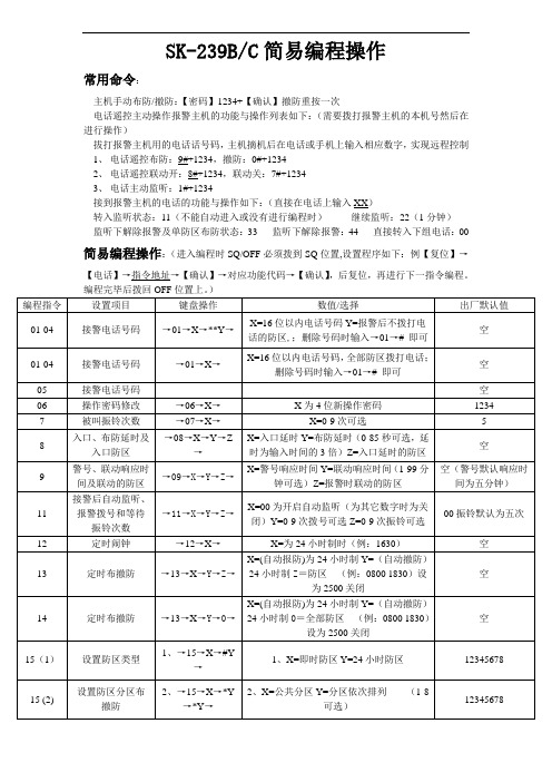
SK-239B/C简易编程操作
常用命令:
主机手动布防/撤防:【密码】1234+【确认】撤防重按一次
电话遥控主动操作报警主机的功能与操作列表如下:(需要拨打报警主机的本机号然后在进行操作)
拔打报警主机用的电话话号码,主机摘机后在电话或手机上输入相应数字,实现远程控制
1、电话遥控布防:9#+1234,撤防:0#+1234
2、电话遥控联动开:8#+1234,联动关:7#+1234
3、电话主动监听:1#+1234
接到报警主机的电话的功能与操作如下:(直接在电话上输入XX)
转入监听状态:11(不能自动进入或没有进行编程时)继续监听:22(1分钟)
监听下解除报警及单防区布防状态:33 监听下解除报警:44 直接转入下组电话:00 简易编程操作:(进入编程时SQ/OFF必须拨到SQ位置,设置程序如下:例【复位】→【电话】→指令地址→【确认】→对应功能代码→【确认】,后复位,再进行下一指令编程。
特别注意!编程操作完毕时,请把‘授权/关闭’(SQ/OFF)开关,拔向“OFF"授权关闭的位置上,否侧机盖上锁以后有可能被人为重新编程设定,使程序错乱或错误删除报警电话号码。
SK239K-B

图(3)LED 显示分体键盘背面 ⑧、引线连接端子:与用户主机的键盘接口对应连接。 ⑨、防拆开关:分体键盘防拆开关。
图(4)用户主机内部结构 ⑩、钮扣式电池:断电后给时钟模块提供电源。 11、拨码开关
密码复原开关(1 号):如果用户忘记更改后的密码时,打开主机,将 1 号拨码开关拨至“ON”位置,即可使密码复原为出厂原始密码“000000”, 进入后重新设置新密码。操作完毕请拨至“1”位置。(出厂拨至“1”位置)。
用户主机在布防状态 下(按退出健切换)
数码管显示"BF"
对应1~16总线制防区 布撤防状态(指示灯亮
6
表示相应防区布防,灭
表示相应防区撤防)
对 应 17~32 总 线 制 防
数码管显示"B2"
区布撤防状态(指示灯 亮表示相应防区布防,
灭表示相应防区撤防)
对应1~8分线制有线防
数码管显示"B3"
区线路状态(指示灯亮 表示相应防区故障,灭
名词解释
布 防:对被保护区内外所有防区布置安全防范任务(指防盗),也叫做 设防或警戒。
旁 路:不对某防区进行戒备,即禁止使用该防区。如某一防区出现故 障或用户暂时不想使用该防区,可将该防区旁路。
撤:安装在各用户中的报警控制器,可受理或控制各种探测器的传
用户主机状态
⑤LED数码管显示内容 1~16指示灯状态指示
用户主机在撤防状态 下(按退出健切换)
数码管显示"CF" 数码管显示"C2" 数码管显示"C3"
对 应 1~16 总 线 制 防 区 使用状态(指示灯亮表 示相应防区有使用,灭 表示相应防区未使用) 对应17~32总线制防区 使用状态(指示灯亮表 示相应防区有使用,灭 表示相应防区未使用) 对应1~8分线制有线防 区线路状态(指示灯亮 表示相应防区故障,灭 表示相应防区正常)
三星 SCH-S239 说明书

< > 尖括号— 在各屏幕上控制不同功能的软键。 例如:<确认> (表示确认软键)。
版权信息
本机所采用的技术和产品的权利归各自的所有人所 有:
Java™ 是 Sun Microsystems 公司的商标。
使用本说明书 3
目录
安装 .................................... 8
WAP ................................. 49
浏览器 ..................................... 49 天翼 ........................................ 51 Samsung Apps ....................... 52 爱音乐 ..................................... 52 天翼空间 ................................... 52 UC 浏览器 ................................ 52 QQ ......................................... 53 淘宝无线 ................................... 53
• 如果手机无法正常充电,请将手机和充电器拿 到三星服务中心。
10 安装
4 当电池充满电(电池图标不再移动)时,断开旅 行充电器与手机的连接,然后将其从电源插座中 拔下。 • 请勿在取下旅行充电器前取出电池。否则会 损坏手机。 • 如欲确保达到最佳电池性能,请先将电池完全 充电和放电(将电池用完)两三次。
SK-3系列智能手动操作器说明书

热偶或高温计输入: 应采用与热偶对应的补偿导线作为延长线,最好有屏蔽。
RT D(铂 电阻) 输入: 三根 导线的 电阻必 须 相 同,每根 导线 电 阻不 能超过15Ω。
3、 通电 设 置 仪 表接 通 电 源后 进 入自 检(自检 状态见 下图),自检 完 毕后 ,仪 表
在点动输出时,可以实现阀位点动关小
增加键:用于增加数值
带打印功能时,用于手动打印
在点动输出时,可以实现阀位点动开大
2、仪 表配线
仪表在现场布线注意事项:
PV 输 入 (测 量 输入)
2
1) 减小 电 气干 扰,低 压 直流 信号 和传感 器输入 的连线 应 远 离强 电 走线。如果做不到应采用屏蔽导线,并在一点接地。
第一输出零点
0~1. 2 00
第 一输出 零点 迁移量(见注2 )
5
名称 第一输出比例
设定范围(字)
说明
0~1. 20 0
第一输 出的放 大比 例(见注2)
第一输出下限
全量程
第一输出的下限量程
第一输出上限 第二输出方式 第二输出零点
全量程 0~2
0~1. 20 0
第一输出的上限量程
2 T=0: 外给定 变送输 出 2 T=1: 阀位反 馈值变 送输 出 2 T=2: 模拟控 制输出
DC24V/2A(大) 见备注
≤30mA
综合参数
测量 精度 0. 2%FS 1字
设定方式 面板轻触式按键数字设定;参数设定值密码锁定;设定值断 电永久保存。
-1999~9 9 99外给 定显 示、 设定 值显 示、 控制 目标 值显 示,