ADG702BRMZ-REEL7中文资料
adg706bruz原理和用法

adg706bruz原理和用法
adg706bruz是一款电源管理解决方案,广泛应用于电子设备中。
下面是adg706bruz的原理和用法的详细介绍:
原理:
adg706bruz采用CMOS技术,具有低功耗和高开关速度的特点。
它包括四个模拟开关和一个可编程增益放大器。
这些开关可以通过栅极电位控制开启或关闭,从而实现信号的传输和路由。
放大器可以通过外部电源电压进行调节,实现不同增益的输出。
用法:
1.模拟信号开关:adg706bruz的四个模拟开关可以用来连接或
切断模拟信号的路径。
通过调节开关的栅极电位,可以实现不同信号的交换、选择和分配。
这在模拟信号处理和信号开关电路中非常常见。
2.电池管理:adg706bruz中的放大器模块可以通过调节外部电
源电压来实现电池的管理。
通过检测电池电压,并通过提供合适的电源电压,可以实现电池电压的保护和控制。
3.电源选择:adg706bruz可以用作电源选择开关。
通过调节开
关的栅极电位,可以选择不同的电源输入。
这对于需要多个电源输入的设备非常有用,可以实现电源的切换和备份。
总之,adg706bruz是一款功能强大的电源管理解决方案,广泛应用于模拟信号处理、电池管理和电源选择等领域。
AZ742中文资料
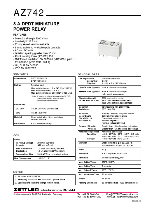
GENERAL DATALife ExpectancyMinimum operations Mechanical 3 x 10⁷Electrical 1 x 10⁵at 8 A 250 VAC res.Operate Time (typical)7 ms at nominal coil voltage Release Time (typical)3 ms at nominal coil voltage (with no coil suppression)Dielectric Strength 5000 Vrms coil to contact(at sea level for 1 min.)2500 Vrms between contact sets1000 Vrms between open contacts Insulation 105megohms min. at 500 VDC,Resistance 20°C, 50% RHInsulation B250 at 2 Form C, flux proof version (according to C250 at other relay versions DIN VDE 0110, Overvoltage category: III IEC 60664-1)Pollution degree: 3Nominal voltage: 250 VACDropout DC coilsGreater than 10% of nominal coil voltage AC coilsGreater than 15% of nominal coil voltage Ambient TemperatureAt nominal coil voltageOperating-40°C (-40°F) to 85°C (185°F) - DC coils -40°C (-40°F) to 70°C (158°F) - AC coils Storage-40°C (-40°F) to 105°C (221°F)Vibration Break contacts: 5 g at 20…500 Hz Make contacts: 20 g at 30…500 Hz Shock 20 gEnclosure P.B.T. polyester, UL-94 : V0TerminalsTinned copper alloy, P.C.Max. Solder Temp.270°C (518°F)Max. Solder Time5 seconds Max. Solvent Temp.80°C (176°F)Max. Immersion Time 30 seconds Weight14 gramsPacking unit in pcs20 per carton tube / 1000 per carton boxZET TLER8 A DPDT MINIATURE POWER RELAYFEATURES •Dielectric strength 5000 Vrms •Low height: 15.7 mm•Epoxy sealed version available•8 Amp switching — double pole contacts •AC and DC coils•Isolation spacing greater than 10 mm •Proof tracking index (PTI/CTI) 250•Reinforced insulation, EN 60730-1 (VDE 0631, part 1)EN 60335-1 (VDE 0700, part 1)•UL, CUR file E43203 •VDE file 40012572CONTACTSArrangement DPDT (2 Form C)DPST (2 Form A)RatingsResistive load:Max. switched power: 2 X 240 W or 2000 VA Max. switched current: 2 X 8 AMax. switched voltage:300 VDC* or 400 VAC* Note: If switching voltage is greater than 30VDC,special precautions must be taken.Please contact the factory.Rated Load UL, CUR 8 A at 250VAC General Use VDE 8 A at 250 VACMaterial Silver nickel, silver nickel gold plated or silver tin oxide Resistance< 100 milliohms initiallyCOILPowerAt Pickup Voltage 200 mW (DC coil)(typical).422 VA (AC coil)Max. Continuous 1.7 W at 20°C (68°F) ambient Dissipation 1.7 VA at 20°C (68°F) ambient Temperature Rise 26°C (47°F) at nominal coil voltage Max. Temperature155°C (311°F)NOTES1.All values at 20°C (68°F).2.Relay may pull in with less than “Must Operate” value.3.Specifications subject to change without notice.ZET TLER* “2A” or “2C” denote silver nickel contacts.Add suffix “G” at “2A” or “2C” for gold plated silver nickel contacts. Add suffix “E” at “2A” or “2C” for silver tin oxide contacts.Add suffix “E” at the end of order number for sealed version.COIL SPECIFICATIONS - AC COILORDER NUMBER*Nominal CoilMust OperateMax. ContinuousNominal CurrentCoil Resistance 2 Form A 2 Form C VACVACVACmA ± 10%Ohm ± 10%129.018.063.0100AZ742–2A–12A AZ742–2C–12A 2418.036.031.3400AZ742–2A–24A AZ742–2C–24A 4836.072.015.61,550AZ742–2A–48A AZ742–2C–48A 6045.090.012.52,600AZ742–2A–60A AZ742–2C–60A 11082.5165.0 6.88,900AZ742–2A–110A AZ742–2C–110A 11586.3172.5 6.59,600AZ742–2A–115A AZ742–2C–115A 12090.0180.0 6.310,200AZ742–2A–120A AZ742–2C–120A 220165.0330.0 3.435,500AZ742–2A–220A AZ742–2C–220A 230172.5345.0 3.338,500AZ742–2A–230AAZ742–2C–230A 240180.0360.03.142,500AZ742–2A–240AAZ742–2C–240ARELAY ORDERING DATACOIL SPECIFICATIONS - DC COILORDER NUMBER*Nominal CoilMust OperateMax. ContinuousCoil Resistance 2 Form A 2 Form C VDCVDCVDCOhm ± 10%3 2.17.622AZ742–2A–3D AZ742–2C–3D 5 3.512.760 AZ742–2A–5DAZ742–2C–5D 6 4.215.390AZ742–2A–6D AZ742–2C–6D 9 6.322.9200AZ742–2A–9D AZ742–2C–9D 128.430.6360 AZ742–2A–12D AZ742–2C–12D1812.645.9710AZ742–2A–18D AZ742–2C–18D 2416.861.21,440 AZ742–2A–24DAZ742–2C–24D 3625.292.03,140AZ742–2A–36D AZ742–2C–36D 4833.6122.05,700AZ742–2A–48D AZ742–2C–48D 6042.0153.07,500AZ742–2A–60D AZ742–2C–60D 11077.0280.025,200AZ742–2A–110DAZ742–2C–110DACCESSORIESMECHANICAL DATAZETTLERh = 15 ... 16.5 mm h = 15 ... 16.5 mmFor P.C.B. mount: Socket EC 50Retaining Clip MP 16 / MH 16For DIN rail mount: Socket ES 50Retaining Clip MS 16ZET TLER。
AD822BRZ中文资料

Applications Information .............................................................. 20 Input Characteristics.................................................................. 20 Output Characteristics............................................................... 20 Single-Supply Voltage-to-Frequency Converter .................... 21 Single-Supply Programmable Gain Instrumentation Amplifier ..................................................................................... 22 3 V, Single-Supply Stereo Headphone Driver ......................... 22 Low Dropout Bipolar Bridge Driver........................................ 23
High load drive Capacitive load drive of 350 pF, G = +1 Minimum output current of 15 mA
Excellent ac performance for low power 800 μA maximum quiescent current per amplifier Unity-gain bandwidth: 1.8 MHz Slew rate of 3 V/μs
清晰通信 MS-702 双通道主站说明书

The MS-702is a one-rack-space, two-channel main station with aregulated 1.2-amp “fail-safe” power supply, individual channel short-circuit protection, and a versatile intercom monitoring system. It supports two intercom channels with up to 40 beltpacks or 10 speaker stations. It features Clear-Com’s excellent speech intelligibility in both high- and low-noise environments.Monitoring SystemThe MS-702 can monitor intercom activity on one or both channels with individual listen-level controls. Monitoring intercom activity is possible through a headset or the internal loudspeaker. The high-sensitivity internal speaker provides intelligible communication in the typical active production environment.Talk SelectionThe MS-702 contains mic preamps with limiters, and speech-shaping circuits for enhanced intelligibility. An individual electronic momentary/latching talk button is provided for each channel. These buttons lightdimly when latched - blue-color LED while in stand-by and amber-color LED when latched. The channels may be accessed separately or simultaneously without tying them together. An optional gooseneck mic is available. Announce OutputFor paging applications, the MS-702 provides a balanced, line-level output signal to a 1/4-inch TRS connector on the rear panel. The front panel “Announce” button activates the output and the Announce relay. The relay circuit, on a separate 1/4-inch TRS connector, is typically used to mute control-room monitors during live announcements.Visual And Audible SignalingVisual “call” signaling attracts the attention of operators who have removed their headsets or turned off their speakers. Call buttons for each channel signal all stations on that party line by flashing brightly. Along with the visual signal, the station’s speaker will emit an audible signal if the remote station operator holds the Call button for more than 2 seconds.Remote Mic Kill (RMK)The MS-702 is equipped with a global RMK button. It will turn off the micro-phone talk circuits of all Clear-Com beltpacks in the system, eliminating extraneous noise from the “open” headset microphones.Program InputThe MS-702 accepts a line-level external program input for monitoring in the headset and speaker, and/or mixing with intercom audio on either or both channels. When Interrupt is selected, the program signal is interrupted when the Talk button is pressed.Power Supply & System ProtectionThe MS-702 provides visual indication of power supply conditions. In the event of a short circuit or current overload on a channel, that channel will shut down while the other one continues to operate. As soon as the fault condition is removed, the “auto-reset” circuitry will restore power to that channel - even under full load conditions.Simple Set-UpThe MS-702 connects to remote stations with standard, two-conductor shielded mic cable. User-selectable setup dip switches are provided on the rear panel.Features:• Supports up to 40 beltpacks or 10 speaker stations on two channels and 12 headsets • Separate short-circuit protection for each channel• Dual-action electronic momentary/ latching “talk” buttons• Program feed to both channels, with selectable “Program Interrupt” (IFB) • “Call” signal buttons for each channel • Global “Remote Mic Kill”• Announce output with relay • Microphone limiting• Volume controls for each channel• Visual and audible “Tone Alert” signaling • Channels A & B “Link” switch • Built-in speaker• Optional gooseneck mic• External switchable line termination on each channel• Universal voltage power supply for 100-240 VAC operationMS-702 Front PanelAmericas & Asia 850 Marina Village Parkway, Alameda, CA 94501 USA Tel: +1.510.337.6600Europe, Middle East & Africa 7400 Beach Drive, Cambridge Research Park, Cambridge, UK Tel: +44 1223 815000© 2007, Vitec Group Communications, LLC. All rights reserved. ® Clear-Com is a registered trade mark of The Vitec Group plc.Technical Specifications:dBu is an absolute measurement. 0 dBu is referenced to 0.775 volts RMS Panel Microphone Input Input Type:Electret Input Impedance:>=2KΩMic Limiter Threshold:0 dBu ±3 dB Mic Limiter Range:>= 20 dB Headset Microphone Input Input Type:Dynamic Input Impedance:>= 1KΩMic Limiter Threshold:0 dBu ± 3dB Mic Limiter Range:>= 15 dBProgram Line Input Maximum Level before Clipping:>= 20 dBu Input Impedance:>= 5KΩHeadset Output Load Impedance:>= 8ΩOutput Impedance:<= 25ΩOutput Limiter Threshold:+5 dBu ± 3 dB Maximum Output Level before Distortion:>= 17 dBu Speaker Output Load ImpedancE:>= 4ΩMax Output Level before 1% Distortion:20 dBu ± 2 dBu Party Line Output Off Noise:< -74 dBu Output Impedance:>10 KΩParty Line Input Crosstalk:< -60 dB Max level before Clipping:>= 12 dBu Sidetone Null Capability:> 25 dBStage Announce/Balanced Line Out Type:Balanced Output Impedance:>= 200ΩLoad Impedance:>= 600ΩIFB/Hot Mic Type :Unbalanced Output Impedance:180ΩLoad Impedance:>= 600ΩFrequency Response Panel Mic - Party Line:600 - 10KHz ± 3dB Headset Mic - Party Line:200 - 12KHz ± 3 dB Headset Mic - Line Out:200 - 12KHz ± 3 dB Program Input - Party Line: 100 17KHz ± 3 dB Program Input - Headset Out: 200 - 10KHz ± 3 dB Program Input - Speaker Out:300 - 10KHz ± 3 dB Party Line - Headset Out:200 - 10KHz ± 3 dB Party Line - Speaker Out:300 - 10KHz ± 3 dBMax DistortionPanel Mic - Party Line:<= 0.5%Headset Mic - Party Line:<= 0.5%Headset Mic - Line Out:<= 0.5%Program Input - Party Line:<= 0.2%Program Input - Headset Out:<= 0.2%Program Input - Speaker Out:<= 0.5%Party Line - Headset Out:<= 0.2%Party Line - Speaker Out:<= 0.5%NoisePanel Mic - Party Line: < -65 dBu Headset Mic - Party Line: < -70 dBu Headset Mic - Line Out: < -55 dBu Program Input - Party Line: < -85 dBu Program Input - Headset Out: < -60 dBu Program Input - Speaker Out:< -60 dBu Party Line - Headset Out:< -50 dBu Party Line - Speaker Out:< -50 dBuMax GainPanel Mic - Party Line: >= 37 dB Headset Mic - Party Line: 41 dB ± 2 dB Headset Mic - Hot Mic Out:55 dB ± 3 dB Headset Mic - Announce Out:55 dB ± 3 dB Program Input - Party Line:>= -16 dB Program Input - Headset Out:>= 18 dB Program Input - Speaker Out:>= 24 dB Party Line - Headset Out:>= 34 dB Party Line - Speaker Out:>= 40 dB Min GainPanel Mic - Party Line” <= 25 dB Mains PowerInput Voltage Range: 100 - 240 VAC Input Frequency Range: 50 - 60 Hz Input Power: <= 60 VAC Output Voltage :30 VDC ± 0.5V Output Current per Channel(Continuous): 1.2 A Output Current per Channel (Peak): 2 A (Do not exceedthe 1.2A rating formore than 2 seconds per 1 minute period)Short Circuit RecoveryTime (1st short):<= 0.5 sec Short Circuit Recovery Time >= 20 shorts in 20sec: <= 20 sec Station CapacityUp to 40 RS-601 beltpacks or 10 speaker stations or 12 headset stations distributed over both channelsRear Panel Connectors Intercom:(6) XLR-3M (3 per channel)Announce Out:(1) XLR-3M (audio)Announce Relay: (1) 1/4 in. (0.64 cm)phone jack (relay)Program: (1) XLR-3F Hot Mic / IFB Interface: (1) 1/4 in. (0.64 cm)phone jackAC Power: IEC 320 connector Rear Panel Controls(2) Termination On-Off switches (8) Option switches (1) Power switch(1) Tone alert volume control Front Panel Connectors Panel Mic:(1) 1/4 in. (0.64 cm) panel mounting jackH eadset: (1) XLR-4M Front Panel Controls & Indicators (1) Panel / headset mic switch (1) Announce button (1) Party line link button (2) Program ON-OFF-INTERRUPT switches (3) Program level controls (2) Listen controls(2) Sidetone null controls (2) Talk buttons (2) Call buttons(1) Tone alert button (1) RMK button (1) Speaker ON-OFF switch (2) Short LEDs Environmental32 - 122˚F (0 - 50˚C)Dimensions19 in. W x 1.75 in. H x 6.5 in. D (483 mm x 44 mm x 165 mm)Weight6.06 lbs. (2.75 kg)Notice About SpecificationsWhile Clear-Com makes every attempt to maintain the accuracy of the information contained in its product manuals, that information is subject to change without notice. Performance specifications included in this manual are design-center specifications and are included for customer guidance and to facilitate system installation. Actual operating performance may vary.MS-702 Back Panel。
ADI中文版数据手册说明书

Rev. 0 Document FeedbackInformation furnished by Analog Devices is believed to be accurate and reliable. However , no responsibility is assumed by Analog Devices for its use, nor for any infringements of patents or other rights of third parties that may result from its use. Speci cations subject to change without notice. No license is granted by implication or otherwise under any patent or patent rights of Analog Devices. T rademarks and registered trademarks are the property of their respective owners.One Technology Way, P.O. Box 9106, Norwood, MA 02062-9106, U.S.A.Tel: 781.329.4700 ©2013 Analog Devices, Inc. All rights reserved. Technical Support ADI 中文版数据手册是英文版数据手册的译文,敬请谅解翻译中可能存在的语言组织或翻译错误,ADI 不对翻译中存在的差异或由此产生的错误负责。
如需确认任何词语的准确性,请参考ADI 提供的最新英文版数据手册。
典型应用电路CHANNEL 2BUCK REGULATOR (1.2A/2.5A/4A)CHANNEL 3BUCK REGULATOR(1.2A)OSCILLATOR INT VREG 100mAQ1Q2L1L2VREGSYNC/MODERT FB1BST1SW1DL1PGND DL2SW2BST2FB2L3BST3SW3FB3PGND3L4BST4SW4FB4PGND4VREGPVIN1COMP1EN1PVIN2COMP2EN2PVIN3PWRGD SS34COMP3EN3PVIN4COMP4EN4C2C1C4C3C5C6C7C8C9C10C11C12C134.5V TO 15VVOUT1VOUT2VOUT3VOUT4R ILIM1R ILIM2VREGEXPOSED PADSS12C0VDDCHANNEL 5200mA LDO REGULATORFB5PVIN5EN5VOUT5C14C15VOUT51.7V TO 5.5VADP5052CHANNEL 1BUCK REGULATOR (1.2A/2.5A/4A)CHANNEL 4BUCK REGULATOR(1.2A)10900-001图1.带四通道降压调节器和200 mA LDO 调节器的5通道集成式电源解决方案产品特性宽输入电压范围:4.5 V 至15 V输出精度:±1.5%(整个温度范围内)可调开关频率范围:250 kHz 至1.4 MHz 可调/固定输出选项,可通过工厂熔丝调节电源调节通道1和通道2:带低端FET 驱动器的可编程1.2 A/2.5 A/4 A 同步降压调节器通道3和通道4:1.2 A 同步降压调节器通道5:200 mA 低压差(LDO)调节器针对小负载要求,5.1 V LDO 电源始终处于激活状态8 A 单通道输出(通道1和通道2并联工作)精密使能,0.8 V 精确阈值有源输出放电开关FPWM 或自动PWM/PSM 模式选择频率同步输入或输出针对OVP/OCP 故障提供可选的闩锁保护所选通道的电源良好指示UVLO 、OCP 和TSD 保护48引脚7 mm × 7 mm LFCSP 封装结温范围:−40°C 至+125°C应用小型蜂窝基站FPGA 和处理器应用安防和监控医疗应用概述ADP5052在一个48引脚LFCSP 封装中集成了四个高性能降压调节器和一个200 mA 低压差(LDO)调节器,可满足严苛的性能和电路板空间要求。
安川变频器GA700 程序手册说明书
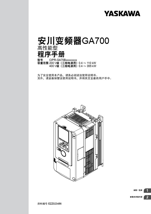
参数一览表参数的详细内容资料编号EZZ023486安川变频器GA700高性能型程序手册型号CIPR-GA70Bxxxxxxxx容量范围200V 级(三相电源用)0.4~110kW400V 级(三相电源用)0.4~355kW为了安全使用本产品,请务必阅读该使用说明书。
另外,请妥善保管该使用说明书,并将其交至最终用户手中。
2株式会社安川電機EZZ023486安川变频器GA700程序手册目录1.参数一览表 (7)1.1安全注意事项 (8)1.2参数一览表的阅读方法 (9)表示控制模式的图标和术语 (9)1.3参数组 (10)1.4A:环境设定 (11)A1:环境设定模式 (11)A2:常用参数的设定模式 (12)1.5b:应用程序 (13)b1:运行模式选择 (13)b2:直流制动/短路制动 (14)b3:速度搜索 (14)b4:定时功能 (16)b5:PID控制 (16)b6:DWELL功能 (19)b7:DROOP控制 (19)b8:节能控制 (20)b9:零伺服 (21)1.6C:调谐 (22)C1:加减速时间 (22)C2:S字特性 (22)C3:滑差补偿 (23)C4:转矩补偿 (24)C5:速度控制(ASR:Automatic Speed Regulator) (24)C6:载波频率 (26)1.7d:指令 (27)d1:频率指令 (27)d2:频率的上限/下限 (28)d3:跳跃频率 (28)d4:频率指令保持指令、UP/DOWN指令、UP2/DOWN2指令 (29)d5:转矩控制 (29)d6:励磁减弱和励磁增强 (30)d7:偏置频率 (30)1.8E:电机参数 (31)E1:电机1的V/f特性 (31)E2:电机1参数 (32)E3:电机2的V/f特性 (32)E4:电机2的参数 (33)E5:PM电机的参数 (33)E9:电机选择 (34)1.9F:选购卡 (35)F1:PG速度控制卡 (35)F2:模拟量输入卡(AI-A3) (36)F3:数字式输入卡(DI-A3) (37)株式会社安川電機EZZ023486安川变频器GA700程序手册3F4:模拟量监视卡(AO-A3) (38)F5:数字式输出选购卡(DO-A3) (38)F6:通信选购卡的设定 (39)F7:通信选购卡的设定 (42)1.10H:端子功能选择 (45)H1:多功能接点输入 (45)H2:多功能接点输出 (49)H3:多功能模拟量输入 (55)H4:多功能模拟量输出 (57)H5:MEMOBUS通信 (58)H6:脉冲序列输入输出 (59)H7:虚拟端子功能 (60)1.11L:保护功能 (62)L1:电机保护功能 (62)L2:瞬时停电处理 (62)L3:防止失速功能 (63)L4:频率检出 (65)L5:故障重试 (66)L6:过转矩/转矩不足检出 (66)L7:转矩极限 (67)L8:硬件保护 (67)L9:硬件保护2 (70)1.12n:特殊调整 (71)n1:防止失调功能 (71)n2:速度反馈检出抑制功能 (71)n3:高滑差制动、过励磁减速 (72)n4:无PG高级矢量特殊调整 (72)n5:前馈控制 (73)n6:电机线间电阻在线变更 (73)n7:EZ矢量控制调整 (73)n8:PM电机控制 (74)1.13o:操作器相关参数 (76)o1:操作器的显示设定 (76)o2:操作器的功能设定 (78)o3:参数备份功能 (79)o4:维护监视的设定 (79)o5:数据日志功能 (80)1.14q:DriveWorksEZ参数 (81)q1-01~q8-40:DriveWorksEZ预约范围 (81)1.15r:DriveWorksEZ连接参数 (82)r1-01~r1-40:DriveWorksEZ连接参数 (82)1.16T:自学习 (83)T0:自学习模式 (83)T1:感应电机的电机参数自学习 (83)T2:PM电机的电机参数自学习 (84)T3:控制自学习 (85)T4:EZ自学习 (85)1.17U:监视 (86)U1:状态监视 (86)U2:故障跟踪 (88)U3:故障记录 (90)U4:维护监视 (90)U5:应用程序监视 (93)U6:控制监视 (94)U8:DriveWorksEZ用的用户监视 (96)1.18出厂设定值随A1-02[控制模式的选择]而变化的参数 (97)1.19出厂设定值随E3-01[电机2的控制模式选择]而变化的参数 (101)4株式会社安川電機EZZ023486安川变频器GA700程序手册1.20出厂设定值随E1-03[V/f曲线]而变化的参数 (102)1.21出厂设定值随o2-04[变频器容量选择]和C6-01[轻载/重载选择]而变化的参数 (104)200V级 (104)400V级 (110)1.22出厂设定值随E5-01[PM电机代码的选择]而变化的参数 (119)安川SMRA系列SPM电机 (119)安川SSR1系列IPM电机(递减转矩用) (120)安川SST4系列IPM电机(恒定转矩用) (128)2.参数的详细内容 (139)2.1安全注意事项 (140)2.2A:环境设定 (141)A1:环境设定模式 (141)A2:常用参数的设定模式 (158)2.3b:应用程序 (160)b1:运行模式选择 (160)b2:直流制动/短路制动 (170)b3:速度搜索 (173)b4:定时功能 (180)b5:PID控制 (181)b6:DWELL功能 (195)b7:DROOP控制 (196)b8:节能控制 (197)b9:零伺服 (201)2.4C:调谐 (203)C1:加减速时间 (203)C2:S字特性 (207)C3:滑差补偿 (208)C4:转矩补偿 (212)C5:速度控制(ASR:Automatic Speed Regulator) (213)C6:载波频率 (221)2.5d:指令 (225)d1:频率指令 (225)d2:频率的上限/下限 (230)d3:跳跃频率 (231)d4:频率指令保持指令、UP/DOWN指令、UP2/DOWN2指令 (232)d5:转矩控制 (236)d6:励磁减弱和励磁增强 (241)d7:偏置频率 (241)2.6E:电机参数 (243)E1:电机1的V/f特性 (243)E2:电机1参数 (249)E3:电机2的V/f特性 (251)E4:电机2的参数 (253)E5:PM电机的参数 (255)E9:电机选择 (258)2.7F:选购卡 (261)F1:PG速度控制卡 (261)F2:模拟量输入卡(AI-A3) (267)F3:数字式输入卡(DI-A3) (268)F4:模拟量监视卡(AO-A3) (272)F5:数字式输出选购卡(DO-A3) (274)F6,F7:通信选购卡的设定 (277)2.8H:端子功能选择 (295)H1:多功能接点输入 (295)株式会社安川電機EZZ023486安川变频器GA700程序手册5多功能接点输入的设定值 (298)H2:多功能接点输出 (314)H2:多功能接点输出参数 (316)多功能接点输出的设定值 (322)H3:多功能模拟量输入 (335)H3:多功能模拟量输入参数 (336)多功能模拟量输入的设定值 (340)H4:多功能模拟量输出 (345)H5:MEMOBUS通信 (348)H6:脉冲序列输入输出 (351)H7:虚拟端子功能 (354)2.9L:保护功能 (358)L1:电机保护功能 (358)L2:瞬时停电处理 (363)L3:防止失速功能 (371)L4:频率检出 (379)L5:故障重试 (380)L6:过转矩/转矩不足检出 (382)L7:转矩极限 (386)L8:硬件保护 (389)L9:硬件保护2 (396)2.10n:特殊调整 (397)n1:防止失调功能 (397)n2:速度反馈检出抑制功能 (399)n3:高滑差制动、过励磁减速 (399)n4:无PG高级矢量特殊调整 (402)n5:前馈控制 (404)n6:电机线间电阻联机调整 (407)n7:EZ矢量控制调整 (407)n8:PM电机控制 (409)2.11o:操作器的设定 (415)o1:操作器的显示设定 (415)o2:操作器的功能设定 (421)o3:参数备份功能 (424)o4:维护监视的设定 (426)o5:数据日志功能 (428)2.12T:自学习 (433)T0:自学习模式 (433)T1:感应电机的电机参数自学习 (433)T2:PM电机的电机参数自学习 (435)T3:控制自学习 (438)T4:EZ自学习 (439)索引 (441)改版记录 (445)6株式会社安川電機EZZ023486安川变频器GA700程序手册1参数一览表1.1安全注意事项 (8)1.2参数一览表的阅读方法 (9)1.3参数组 (10)1.4A:环境设定 (11)1.5b:应用程序 (13)1.6C:调谐 (22)1.7d:指令 (27)1.8E:电机参数 (31)1.9F:选购卡 (35)1.10H:端子功能选择 (45)1.11L:保护功能 (62)1.12n:特殊调整 (71)1.13o:操作器相关参数 (76)1.14q:DriveWorksEZ参数 (81)1.15r:DriveWorksEZ连接参数 (82)1.16T:自学习 (83)1.17U:监视 (86)1.18出厂设定值随A1-02[控制模式的选择]而变化的参数 (97)1.19出厂设定值随E3-01[电机2的控制模式选择]而变化的参数 (101)1.20出厂设定值随E1-03[V/f曲线]而变化的参数 (102)1.21出厂设定值随o2-04[变频器容量选择]和C6-01[轻载/重载选择]而变化的参数 (104)1.22出厂设定值随E5-01[PM电机代码的选择]而变化的参数 (119)株式会社安川電機EZZ023486安川变频器GA700程序手册71.1安全注意事项8株式会社安川電機EZZ023486安川变频器GA700程序手册参数一览表1.2参数一览表的阅读方法株式会社安川電機EZZ023486安川变频器GA700程序手册9◆表示控制模式的图标和术语图标如下所示。
7N70中文资料

7N70L-TF3-T (1)Packing Type (2)Package Type (3)Lead Plating (1) T: Tube (2) TF3: TO-220F (3) L: Lead Free Plating , Blank: Pb/Sn
Copyright © 2005 Unisonic Technologies Co., Ltd
Power MOSFET
RATINGS UNIT 700 V ±30 V TC = 25°C 7.0 A Continuous Drain Current ID TC = 100°C 4.7 A Drain Current Pulsed (Note 1) IDM 28 A Avalanche Energy, Single Pulsed (Note 2) EAS 530 mJ Avalanche Energy, Repetitive, Limited by TJMAX EAR 14.2 mJ Peak Diode Recovery dv/dt (Note 3) dv/dt 4.5 V/ns Power Dissipation (TC = 25°C) PD 142 W Junction Temperature TJ +150 Storage Temperature TSTG -55 ~ +150 Note Absolute maximum ratings are those values beyond which the device could be permanently damaged. Absolute maximum ratings are stress ratings only and functional device operation is not implied.
AD7028 通讯模块使用手册说明书
AD7028通讯模块使用手册厦门爱陆通通信科技有限公司热线:400-808-5829电话:传真:网址:地址:厦门市集美区杏北二路146-148号、目录目录 (3)第1章产品简介 (5)1.1 产品概述 (5)1.2 产品特点 (5)1.3 工作原理框图 (6)1.4 产品规格 (7)1.5 订购信息 (8)第2章产品安装 (9)2.1 概述 (9)2.2 装箱清单 (9)2.3 安装与电缆连接 (9)2.4 电源说明 (12)2.5指示灯说明 (13)2.6 复位按钮说明 (13)第3章参数配置 (14)3.1 设备与PC连接图 (14)3.2 登录到配置页面 (14)3.2.1 PC机IP地址设置(两种方式) (14)3.2.2 登录到配置界面 (15)3.3 网络基本 (16)3.3.1 广域网 (16)3.3.2 广域网状态 (19)3.3.3 局域网 (19)3.3.4 局域网状态 (21)3.4 网络高级 (22)3.4.1 静态地址分配 (22)3.4.2 高级路由 (22)3.4.3 MAC地址克隆 (23)3.4.4 静态域名解析 (23)3.5 无线设置.......................................................................................... 错误!未定义书签。
3.5.1 基本设置............................................................................... 错误!未定义书签。
3.5.2 无线安全............................................................................... 错误!未定义书签。
3.5.3 无线状态............................................................................... 错误!未定义书签。
- 1、下载文档前请自行甄别文档内容的完整性,平台不提供额外的编辑、内容补充、找答案等附加服务。
- 2、"仅部分预览"的文档,不可在线预览部分如存在完整性等问题,可反馈申请退款(可完整预览的文档不适用该条件!)。
- 3、如文档侵犯您的权益,请联系客服反馈,我们会尽快为您处理(人工客服工作时间:9:00-18:30)。
CMOS Low Voltage 2 Ω SPST Switches
ADG701/ADG702
Rev. C Information furnished by Analog Devices is believed to be accurate and reliable. However, no responsibility is assumed by Analog Devices for its use, nor for any infringements of patents or other rights of third parties that may result from its use. Specifications subject to change without notice. No license is granted by implication or otherwise under any patent or patent rights of Analog Devices. Trademarks and registered trademarks are the property of their respective owners. One Technology Way, P.O. Box 9106, Norwood, MA 02062-9106, U.S.A.Tel: 781.329.4700 www.analog.com Fax: 781.461.3113 © 2006 Analog Devices, Inc. All rights reserved.
FEATURES 1.8 V to 5.5 V single supply 2 Ω (typical) on resistance Low on resistance flatness –3 dB bandwidth > 200 MHz Rail-to-rail operation Fast switching times tON 18 ns tOFF 12 ns Typical power consumption < 0.01 μW TTL/CMOS-compatible APPLICATIONS Battery-powered systems Communications systems Sample-and-hold systems Audio signal routing Video switching Mechanical reed relay replacement FUNCTIONAL BLOCK DIAGRAM DSINADG701DSIN
ADG702
SWITCHES SHOWN FOR A LOGIC 1 INPUT000
3
9-001
Figure 1.
GENERAL DESCRIPTION The ADG701/ADG702 are monolithic CMOS SPST switches. These switches are designed on an advanced submicron process that provides low power dissipation yet high switching speed, low on resistance, and low leakage currents. In addition, −3 dB bandwidths of greater than 200 MHz can be achieved. The ADG701/ADG702 can operate from a single 1.8 V to 5.5 V supply, making it ideal for use in battery-powered instruments and with the new generation of DACs and ADCs from Analog Devices, Inc. Figure 1 shows that with a logic input of 1, the switch of the ADG701 is closed and that of the ADG702 is open. Each switch conducts equally well in both directions when on. The ADG701/ADG702 are available in 5-lead SOT-23, 6-lead SOT-23, and 8-lead MSOP packages. PRODUCT HIGHLIGHTS 1. 1.8 V to 5.5 V Single-Supply Operation. The ADG701/ADG702 offer high performance, including low on resistance and fast switching times, and are fully specified and guaranteed with 3 V and 5 V supply rails.
2. Very Low RON (3 Ω Maximum at 5 V, 5 Ω Maximum at 3 V).
At 1.8 V operation, RON is typically 40 Ω over the tempera-
ture range.
3. On Resistance Flatness RFLAT(ON) (1 Ω Maximum). 4. −3 dB Bandwidth > 200 MHz. 5. Low Power Dissipation. CMOS construction ensures low power dissipation.
6. Fast tON/tOFF.
Table 1. Related Devices Part No. Description ADG701L/ADG702L Low voltage 2 Ω SPST switches
with guaranteed leakage specifications
元器件交易网www.cecb2b.comADG701/ADG702 Rev. C | Page 2 of 12 TABLE OF CONTENTS Features..............................................................................................1 Applications.......................................................................................1 Functional Block Diagram..............................................................1 General Description.........................................................................1 Product Highlights...........................................................................1 Revision History...............................................................................2 Specifications.....................................................................................3 Absolute Maximum Ratings............................................................5 ESD Caution..................................................................................5 Pin Configurations and Function Descriptions...........................6 Typical Performance Characteristics..............................................7 Terminology.......................................................................................8 Test Circuits........................................................................................9 Applications Information..............................................................10 ADG701/ADG702 Supply Voltages.........................................10 Bandwidth...................................................................................10 Off Isolation................................................................................10 Outline Dimensions.......................................................................11 Ordering Guide..........................................................................12