86BSD压力传感器
ASG压力传感器SURSENSE超低压压力传感器,DUXL系列无温度补偿无放大

广州:Tel:020-38791169 - 24 -
e-mail:jian.bo.zhou@
/sensing
DUXL 系列,不带温度补偿
DUXL系列压力传感器提供了线性毫伏输出,小型封装。传感器适合于客户自已 做外部调理电路的应用。
DUXL 电气规格(4.5VdC 供电 @25℃)
供电电压 满量程(除 DUXL01D、DUXL05D 外) 满量程(DUXL01D) 满量程(DUXL05D) 零点 工作温度 储存温度 输入阻抗
ASG 压力传感器 SURSENSE™ 超低压压力传感器,DUXL 系列 无温度补偿 无放大
SURSENSETM 系列超低压压力传感器,采用 一种能减少输出偏置或共模误差的 专利技术。
这种传感器使用了一种特别的硅敏感元件、这种元件具有特殊的压力集中增强结 构,提供了高稳定的与应力成正比的线性输出。这样,与传统的压力传感器相比,由 温度、长时间稳定性和位置灵敏引起的输出偏置误差,可以显著的被消除掉。
P1 口:干燥空气 P2 口:与尼龙外壳,硅兼容的介质
最大值 8.0 45 8.0 30 10 +85 +125
--
单位 V mv mv mv mv ℃ ℃ Ohm
20D
30D
20.0
30.0
200
300
400Βιβλιοθήκη 6005050
DUXL
05
D
系列 DUXL 不带温度补偿且无校正,mv输出
压力范围 英寸水柱
最小值 3.0 15 4.0 15 -10 -25 -40 --
典型值 4.5 30 6.0 22.5 0 --+2.0
DUXL 系列压力范围(英寸水柱)
东风本田汽车常用传感器说明

1.1.2 ECT2
检测空调系统冷却液温度 水温传感器是空调系统的冷却液传感器。由于该传感器将冷却液水循环 至加热器芯,检发动机冷却液温度和信号电压是否与温度-电压特性图匹 配。
17
1.1温度传感器
汽车技术培训 资料
1.1.3 变速箱油温度传感器
1.断开插接器(A)
2.测量插接器 (B) 2 号端子和 3 号端子之间的变
空调
变速箱 制动 AWD
转向
SRS 车身电气 二、传感器故障诊断方法 两线传感器诊断 三线传感器诊断 三、传感器原理、构造及检测 线性传感器 逻辑传感器 频率传感器
4
各系统所包含的传感器
汽车技术培训 资料
序号
系统
1
发动机
2
空调
传感器名称 水温传感器1(ECT1) 进气歧管绝对压力传感器(MAP) 加速踏板位置传感器(APP) 水温传感器2(ECT2) 进气温度传感器(IAT) 节气门位置传感器(TP) EGR阀位置传感器 燃油油位传感器 大气压力传感器(BARO) 燃油压力传感器 摇臂机油压力传感器 空气流量传感器(MAF) 氧传感器 空燃比传感器(A/F) 爆震传感器 凸轮轴与位置传感器(CMP) 曲轴位置传感器(CKP) 机油压力开关 蒸发器温度传感器 车内、车外温度传感器 光照传感器 空调压力传感器
本资料为2015年11月5日第一次修订,第一版。
2
目录
汽车技术培训 资料
一、各系统所包含的传感器 发动机
空调
变速箱 制动 A、传感器故障诊断方法 两线传感器诊断 三线传感器诊断 三、传感器原理、构造及检测 线性传感器 逻辑传感器 频率传感器
3
目录
汽车技术培训 资料
一、各系统所包含的传感器 发动机
WPD-102 压力传感器说明手册说明书

WARNING Ensure that the maximum individual port pressure doesnot exceed the maximum pressure range of the unit. For example, the maximum individual port pressure on a WPD-102 is 100 PSI. Exceed-ing this may damage the sensors and WILL give erroneous readings.WARNING Do not use in an explosive or hazardous environment, with combustible or flammable gasses, as a safety or emergency stop device or in any other application where failure of the product could result in personal injury. Use electrostatic discharge precautions during installation and do not exceed the device ratings.MOUNTING The transmitter mounts on a vertical surface with the pressure ports and cable entrance on the bottom using the two screw holes on the base of the unit. Ensure there is enough space around the unit to make the pressure and electrical connections. Avoid locations with severe vibrations or excessive moisture. The enclosure has a standard ½” conduit opening and may be installed with either a conduit coupler or a cable gland type fitting. In this position the High port is on the left and the Low port is on the right as shown on the pcb.WIRING Use 22 awg shielded wiring for all connections and do not locate the device wires in the same conduit with wiring used to supply induc-tive loads such as motors. Disconnect the power supply before making any connections to prevent electrical shock or equipment damage. Make all connec-tions in accordance with national and local electrical codes.This device is a 3-wire sourcing type transmitter. Connect the positive dc voltage or the hot side of the ac voltage to the terminal marked PWR . The power supply common is connected to the terminal marked COM . The device is reverse voltage protected and will not operate if connected backwards. The analog output signal is available on the OUT terminal. This signal is jumper selectable for either voltage or 4-20 mA output. In voltage mode, either 0-5 or 0-10 Vdc can also be selected. These options are indicated on the circuit board.The remote zero feature may be used by wiring a dry-contact (relay only) digital output to the ZERO terminals. Do not apply voltage to the ZERO terminals.PLUMBING The two pressure ports are labeled High and Low . The out-put signal indicates a positive value when the pressure is higher on the High port than the Low port so ensure these ports are connected correctly. Use an appropriately rated pressure tubing and arrange it to minimize stress on the connections.Do not allow material to fall into the pressure ports as contamination could damage the sensors.CONFIGURATION As shown on the pcb drawing, push-on jumpers and switches are used to select the output signal type, the input pressure range and several features. The device is factory configured to operate in the 4-20 mA output mode but can be changed to voltage mode by moving the two jumpersfrom the positions marked Current to the positions marked Voltage . Always note the current jumper position first and then move them to the new position.If the jumpers are rotated 90 degrees and installed incorrectly the product will not work and damage may occur. In voltage mode the output scale may be changed to either 0-5 or 0-10 Vdc by moving the single jumper to the 5V or 10V position.The Range and Options switches can be changed while the unit is operating. However, the output jumpers can only be changed while the power is removed.The jumper marked Light is for the LCD back-light option. The back-light is enabled in the On position but can be set to Off to reduce power consumption. The input pressure range (as shown on the product label) is set by moving the 4-position slide switch marked RANGE .Bidirectional operation, port swap, slow damping and analog reverse functions are available by switching the appropriate DIP switch position to ON.BIDIRECTIONAL This switch changes the range from 0 to full scale differ-ential pressure to minus full scale to plus full scale differential pressure. The analog output will read ½ when the differential pressure is zero. The example below shows the results when a Model 2 (0 to 100 psi) is operated in bidirec-tional mode (-100 to 100 psi).PORT SWAP This switch reverses the polarity of the pressure ports. It makes the HIGH port “low” and the LOW port “high”. This is useful to correct plumbing errors.SLOW DAMPING This switch provides an 8-second averaging for surge dampening (normally it is 4-seconds).OUTPUT REVERSE This switch reverses the output signal polarity. In reverse mode the analog output is maximum when the pressure differential is zero and decreases as pressure increases.OPERATION For normal operation such as 0-100 PSI, the pressure applied to the High port must be higher than the pressure applied to the Low port. If the pressure connection is reversed then the transmitter will always output 4 mA or 0 V. If the Low port is left open to ambient pressure, then the High port is used to measure a positive pressure and 0 PSI = 4 mA and 100 PSI = 20 mA.Model 1 2 3 4 101 50 PSI 25 PSI 10 PSI 5 PSI 102 100 PSI 50 PSI 20 PSI 10 PSI 103 200 PSI 100 PSI 40 PSI 20 PSI 104 500 PSI 250 PSI 100 PSI 50 PSI 105 5.0 Bar 2.5 Bar 1.0 Bar 0.5 Bar 106 7.50 Bar 3.75 Bar 1.50 Bar 0.75 Bar 107 10 Bar 5 Bar 2 Bar 1 Bar 108 30 Bar 15 Bar 6 Bar 3 Bar 109 500 kPa 250 kPa 100 kPa 50 kPa 110 750 kPa 375 kPa 150 kPa 75 kPa 111 1000 kPa 500 kPa 200 kPa 100 kPa 1123000 kPa1500 kPa600 kPa300 kPaPressure Range Wet-WetDifferential Pressure TransducerInstallation InstructionsHIGH port LOW port LCD 4-20 mA 0-5 V 100 PSI 50 PSI 50 PSI 16 mA 3.75 V 50 PSI 100 PSI -50 PSI 8 mA 1.25 V 50 PSI 50 PSI 0 PSI 12 mA 2.5 V 100 PSI0 PSI100 PSI20 mA5 VFor bidirectional operation such as +/-100 PSI, the pressure applied to the High port should be higher than the pressure applied to the Low port for a positive output response. Negative pressure is indicated if the High pressure is less than the Low pressure. In this case –100 PSI = 4 mA and +100 PSI = 20 mA. Since the transmitter is linear 0 PSI = 12 mA.CALIBRATION With both ports open to the ambient pressure (or with both ports equalized at 0 pressure), press and hold the auto-zero button or provide contact closure on the ZERO terminals for at least 3 seconds. Release the button or terminals and the device will calculate and store the new zero point. To protect the unit from accidental zeroing this feature is enabled only when the detected pressure on both ports is less than 5% of the full range. It is not recommended that the span calibration be performed in the field unless a high quality calibrator is available. SPECIFICATIONSMedia compatibility 17-4 PH stainless steel Input power 15 to 30 Vdc / 24 Vac nominal Supply current @ 24 Vdc 100 mA with LCD backlight 35 mA with backlight disabledOutput signal 4-20 mA, 0-5 or 0-10 Vdc Proof pressure Max. 2x F.S. range Burst pressure Max. 5x F.S. range Accuracy +/-1 %F.S. (range 4 is +/- 2 %) Surge damping 4 sec averaging (8 sec for slow) Long term stability +/-0.25% typical (1 year) Auto-zero adjust pushbutton and remote input Sensor operating range -40 to 105 °C (-40 to 220 °F) Operating environment 0 to 50 °C, 10 to 90 %RH n.c. Fittings 1/8” NPT femaleEnclosure 5” x 5” x 2.25” PVC NEMA 4Optional switch settings. Default is Normal (switch set to off).Power in, 24Vac/dc Common is shared with outputOutput, Current or Voltage.Common is shared with power supplyNOTE: The range and options switch can be changed while the unit is powered. However, the output jumpers can only be changed while the unit is unpowered.DO NOT CONNECT POWER TO THE ‘OUT’ TERMINAL AS THE UNIT WILL BE DAMAGED!REV. 006 10/2008WARNING Ensure that the maximum individual port pressure does not exceed the maximum pressure range of the unit. For example, the maximum individual port pressure on a WPD-102 is 100 PSI. Exceeding this may damage the sensors and WILL give erroneous readings.BOARD LAYOUT WIRINGJUMPER SETTINGSDisplay backlight on Display backlight off4-20 mA output 0-10 Vdc output 0-5 Vdc outputNOTE: The current/voltage output jumpers must be oriented as they are shown in the above illustration.。
森萨塔 SENSATA 压力传感器 86HP

WORLD CLASS PERFORMANCE The 85HP and 86HP series sensors are ideally suited for severe industrial OEM applications requiring long wire runs. Housed in corrosion resistant stainless steel, these sensors include a hermetic front end with a variety of electrical and pressure connection options. Sensata Technologies has been a leading global supplier of pressure sensors & switches for over 50 years.
Current Output, High Accuracy, Hermetic
VsVs (+)
Ordering Information
EXAMPLE Series Pressure Connection Electrical Connection Device Input-Output Pressure Range Pressure Reference EMC Potted Wire Lead Length Total Thermal Effect Standard STANDARD OPTIONS Series Pressure Connection Electrical Connection Device Input-Output Y Pressure Ranges 85HP 85HP 1/4-18 NPT-2A male pipe, 22 mm Standard Packard Metri-Pack Power Input: 4.5-5.5 Vdc, Device Output 0.5-4.5 Vdc 0-0500 psi Sealed Gage Standard-(300 V/m, 1 MHz-400 MHz) 1M Standard Accuracy SPECIAL OPTIONS 85HP Standard Accuracy 86HP High Accuracy 12 M14 x 1.5 male o-ring thread per ISO 6149, 22 mm hex 14 1/8-27 NPT-2A male pipe, 22 mm hex 15 7/16-20 UNF-2B female with Schraeder deflator (Contact factory for availability) 05 3/8-24 UNF-2A male o-ring thread per SAE J514, 22 mm hex 06 1/4-18 NPT-2A male pipe, 22 mm hex 07 7/16-20 UNF-2A male o-ring per SAE J514, 22 mm hex 2 3 Standard Packard Metri-Pack™ Hirschman Mini DIN (GDSN 307) Supply Voltage Vs... 10-32 Vdc 06 2 X 00500 S S 0 A
如何检测压力传感器
如何检测压力传感器
压力传感器的应用范围非常广泛,伴随着压力传感器的广泛应用,确定如何检测压力传感器显得十分重要。
检测压力传感器,根据目的不同,检测的项目也不一样,当然检测的方法也就会有区别。
1、桥路的检测,主要检测传感器的电路是否正确,一般是惠斯通全桥电路,利用万用表的欧姆档,量输入端之间的阻抗、以及输出端之间的阻抗,这两个阻抗就是压力传感器的输入、输出阻抗。
如果阻抗是无穷大,桥路就是断开的,说明传感器有问题或者引脚的定义没有判断正确。
2、零点的检测,用万用表的电压档,检测在没有施加压力的条件下,传感
器的零点输出。
这个输出一般为mV级的电压,如果超出了传感器的技术指标,就说明传感器的零点偏差超范围。
3、加压检测,检单的方法是:给传感器供电,用嘴吹压力传感器的导气孔,用万用表的电压档检测传感器输出端的电压变化。
如果压力传感器的相对灵敏度很大,这个变化量会明显。
如果丝毫没有变化,就需要改用气压源施加压力。
通过以上方法,基本可以检测一个传感器的状况。
如果需要准确的检测,就需要用标准的压力源,给传感器压力,按照压力的大小和输出信号的变化量,对传感器进行校准。
并在条件许可的情况下,进行相关参数的温度检测。
tips:感谢大家的阅读,本文由我司收集整编。
仅供参阅!。
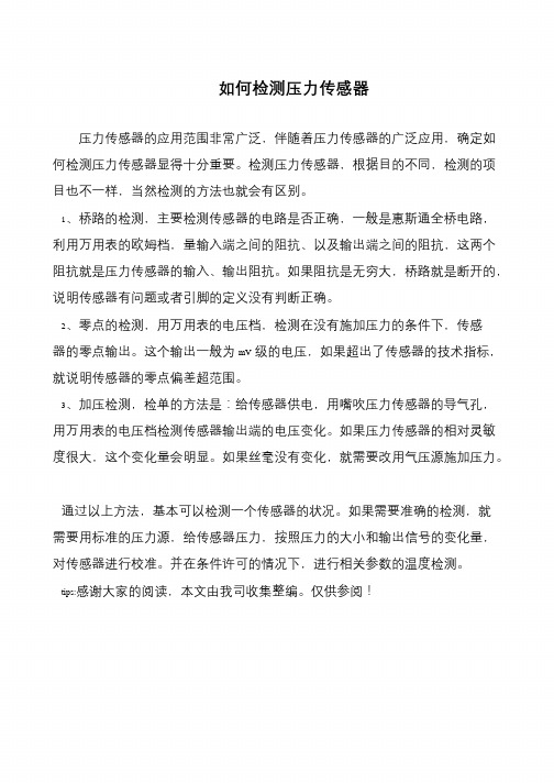
D X N 8 B系列户内高压带电显示装 置 (VPIS) 电压指示器 (可配充气
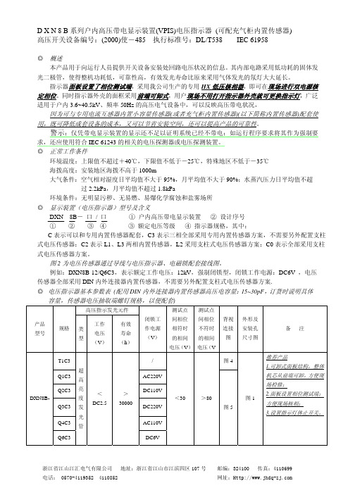
D X N 8 B 系列户内高压带电显示装置(VPIS)电压指示器 (可配充气柜内置传感器) 高压开关设备编号:(2000)使-485 执行标准号:DL/T538 IEC 61958
◎ 概述
本产品用于向运行人员提供开关设备安装处回路电压状况的信息。其内部电路采用低功耗的固体发
光二极管,使得整机功耗低,可靠性高,有效发光寿命比原来采用气体发光的氖灯大大延长。
指示器面板设置了相位测试端,采用我公司生产的专用 HX 低压核相器,即可在现场进行双电源核 定相位。同时指示器外壳的面框采用前端可卸式,用户现场不用打开指示器外壳就可更换指示灯,广泛
式电压传感器方案。
图 2 为电压传感器通过导线与电压指示器、电磁锁配套接线图。
例如:DXN8B-12/Q6C3,表示额定工作电压:12kV,强制闭锁型,闭锁工作电源:DC6V ,电压
传感器全部采用 DIN 内外连接器内置传感器,不需要另外配置支柱式电压传感器方案. ◎ 电压指示器基本参数表 (配用 DIN 内外连接器内置传感器高压电容量:15~30pF,订货时说明具体
适用于户内 3.6~40.5kV、频率 50Hz 的高压电气设备中,可以反映高压带电状况, 因为可与专用电流互感器内置小容量传感器(或者充气柜内置传感器)(以下简称内置传感器)配套使
用,既可降低成套设备的成本,又可以节省安装空间,还可以提高产品的可靠性。
警示:仅凭带电显示装置的显示还不足以证明系统已经不带电:如运行程序要求将其作为强制要
SMC压力传感器调整说明书ZSE30AISE30A

SMC压力传感器调整说明书ZSE30AISE30A关键信息项:1、传感器型号:ZSE30A/ISE30A2、调整目的3、调整工具4、调整步骤5、安全注意事项6、故障排除方法1、引言本协议旨在为用户提供关于 SMC 压力传感器 ZSE30A/ISE30A 的详细调整说明,以确保其正常运行和准确测量压力。
11 适用范围本协议适用于 SMC 压力传感器 ZSE30A/ISE30A 的调整操作。
2、调整目的21 确保传感器测量精度通过调整,使传感器能够准确测量压力值,减少误差。
22 适应不同的工作环境和压力范围根据实际工作需求,调整传感器的参数,以适应各种工作条件。
23 优化传感器性能提高传感器的响应速度、稳定性和可靠性。
3、调整工具31 专用调试设备如 SMC 提供的特定调试工具或软件。
32 标准压力校验仪用于提供准确的压力标准值,以校准传感器。
33 螺丝刀等常用工具用于拆卸和安装传感器的外壳及相关部件。
4、调整步骤41 准备工作411 关闭相关设备的电源,确保操作安全。
412 将传感器从系统中拆卸下来,放置在干净、平稳的工作台上。
42 外观检查421 检查传感器外壳是否有损坏、变形等情况。
422 检查传感器的连接接口是否清洁、无异物。
43 连接调试设备431 将专用调试设备或软件与传感器正确连接。
432 按照调试设备的说明书进行设置和初始化。
44 压力校准441 使用标准压力校验仪向传感器施加不同的压力值。
442 观察传感器的输出值,并与标准压力值进行对比。
443 通过调试设备调整传感器的参数,使输出值与标准压力值相符。
45 功能测试451 对调整后的传感器进行功能测试,包括压力上升和下降时的响应情况。
452 检查传感器在不同压力范围内的稳定性和重复性。
46 安装与恢复461 将调整好的传感器安装回原系统。
462 开启相关设备的电源,检查传感器的工作状态是否正常。
5、安全注意事项51 在操作过程中,务必遵循相关的安全操作规程,防止发生意外事故。
压力传感器的基本工作原理 斯巴拓
斯巴拓传感器---您身边的力传感专家!压力传感器(英文名称:transducer/sensor)是一种检测装置,往往又被称为换能器,能感受到被测量的信息,并能将感受到的信息,按一定规律变换成为电信号或其他所需形式的信息输出,以满足信息的传输、处理、存储、显示、记录和控制等要求。
斯巴拓传感器---您身边的力传感专家!1. 应变片压力传感器原理与应用力学传感器的种类繁多,如电阻应变片压力传感器、半导体应变片压力传感器、压阻式压力传感器、电感式压力传感器、电容式压力传感器、谐振式压力传感器及电容式加速度传感器等。
但应用最为广泛的是压阻式压力传感器,它具有极低的价格和较高的精度以及较好的线性特性。
下面主要介绍这类传感器。
在了解压阻式力传感器时,首先认识一下电阻应变片这种元件。
电阻应变片是一种将被测件上的应变变化转换成为一种电信号的敏感器件。
它是压阻式应变传感器的主要组成部分之一。
电阻应变片应用最多的是金属电阻应变片和半导体应变片两种。
金属电阻应变片又有丝状应变片和金属箔状应变片两种。
通常是将应变片通过特殊的粘和剂紧密的粘合在产生力学应变基体上,当基体受力发生应力变化时,电阻应变片也一起产生形变,使应变片的阻值发生改变,从而使加在电阻上的电压发生变化。
这种应变片在受力时产生的阻值变化通常较小,一般这种应变片都组成应变电桥,并通过后续的仪表放大器进行放大,再传输给处理电路(通常是A/D 转换和CPU)显示或执行机构。
电阻应变片的工作原理:金属电阻应变片的工作原理是吸附在基体材料上应变电阻随机械形变而产生阻值变化的现象,俗称为电阻应变效应。
我们以金属丝应变电阻为例,当金属丝受外力作用时,其长度和截面积都会发生变化,从上式中可很容易看出,其电阻值即会发生改变,假如金属丝受外力作用而伸长时,其长度增加,而截面积减少,电阻值便会增大。
当金属丝受外力作用而压缩时,长度减小而截面增加,电阻值则会减小。
只要测出加在电阻的变化(通常是测量电阻两端的电压),即可获得应变金属丝的应变。
- 1、下载文档前请自行甄别文档内容的完整性,平台不提供额外的编辑、内容补充、找答案等附加服务。
- 2、"仅部分预览"的文档,不可在线预览部分如存在完整性等问题,可反馈申请退款(可完整预览的文档不适用该条件!)。
- 3、如文档侵犯您的权益,请联系客服反馈,我们会尽快为您处理(人工客服工作时间:9:00-18:30)。
86BSD压力传感器(优惠价380元,没现货,最少起订10个)(江门安泰)产品说明:
86BSD压力传感器/86BSD液位传感器是一款小体积、介质兼容、采用316L不锈钢封装的硅压阻压力传感器。
86BSD采用I²C或SPI数字输出,O型圈密封,通过腔体硅油将316L不锈钢膜片的压力传递到传感元件。
86BSD经过温度补偿及ASIC校准,适用于低压力高性能的应用。
所属品牌:MEAS
输出: SPI或I²C(串行、数字接口)(I²C、SPI为通信中数据传输协议,即通信协议。
I²C通信中使用两个信号线SDA、SCL,分别为数据线和时钟线。
SPI通信中使用4根信号线MISI、MISO、SCLK、SS,分别为数据输入、数据输出、时钟和使能端,NC表示空脚。
)
量程: 1psi、2psi、5psi、15psi、30psi、50psi、100psi、150psi、200psi、300psi(1兆帕(MPa)=145磅(psi),1磅(psi)=0.006895兆帕(MPa))
封装:316L不锈钢
工作温度范围:-40℃~125℃
精确度:±0.1%非线性,±1.0 %总误差范围
供电电源:2.7-5.5VDC
特点:稳压一体、O型圈密封、±0.1%非线性精度、低功耗、数字输出、恒压供电
类型:表压、绝压
电气连接:PCB焊接或电缆/连接器
典型应用:液位控制,液位测量,腐蚀性液体和气体测量系统,OEM设备,密封系统,进气压力测量,气压测量,潜水深度监测。