New_20_RT-flex_Comp-Syst_Chinese
UNIS 服务器 操作系统安装指导说明书

UNIS服务器操作系统安装指导紫光恒越技术有限公司资料版本:5W300-20220520Copyright © 2022 紫光恒越技术有限公司及其许可者版权所有,保留一切权利。
未经本公司书面许可,任何单位和个人不得擅自摘抄、复制本书内容的部分或全部,并不得以任何形式传播。
UNIS为紫光恒越技术有限公司的商标。
对于本手册中出现的其它公司的商标、产品标识及商品名称,由各自权利人拥有。
由于产品版本升级或其他原因,本手册内容有可能变更。
紫光恒越保留在没有任何通知或者提示的情况下对本手册的内容进行修改的权利。
本手册仅作为使用指导,紫光恒越尽全力在本手册中提供准确的信息,但是紫光恒越并不确保手册内容完全没有错误,本手册中的所有陈述、信息和建议也不构成任何明示或暗示的担保。
环境保护本产品符合关于环境保护方面的设计要求,产品的存放、使用和弃置应遵照相关国家法律、法规要求进行。
目录1简介 ··························································································································· 1-1 2安装操作系统 ··············································································································· 2-12.1 准备OS镜像 ············································································································ 2-12.2 登录服务器··············································································································· 2-12.2.1 通过本地登录服务器 ·························································································· 2-12.2.2 通过BMC登录服务器远程控制台 ········································································· 2-12.3 连接OS镜像文件 ······································································································ 2-22.4 配置RAID ················································································································ 2-32.5 选择启动介质············································································································ 2-32.6 安装银河麒麟操作系统 ································································································ 2-4 3查看并安装设备驱动程序 ································································································ 3-13.1 检查设备驱动程序······································································································ 3-13.2 安装设备驱动程序······································································································ 3-2 4常见问题解答 ··············································································································· 4-14.1 如何远程控制服务器? ································································································ 4-14.2 如何制作可引导U盘 ·································································································· 4-14.2.1 使用Win32DiskImage制作可引导U盘·································································· 4-14.2.2 使用UltraISO制作可引导U盘············································································· 4-24.2.3 使用Linux dd命令制作可引导U盘······································································· 4-34.3 如何使用PXE方式安装操作系统?················································································ 4-34.4 如何查看系统的内核版本? ·························································································· 4-54.5 RAID卡支持哪些RAID级别? ······················································································ 4-64.6 设备出厂是否默认安装了操作系统? ·············································································· 4-6 5技术支持 ····················································································································· 5-15.1 技术支持网址············································································································ 5-15.2 获取技术支持············································································································ 5-1 6缩略语 ························································································································ 6-1手册中涉及的软件界面可能会不定期更新,请以产品实际显示界面为准。
Lenovo Flex System x280 X6和x480 X6计算节点类型7196ADU和DD
Technical Update Lenovo Flex System x280X6and x480X6Compute Node Type7196models ADU and DDUThis Technical Update supplements the Lenovo®Flex System™x280X6,x480X6,and x880X6Compute Node Types7196and4258Installation and Service Guide that comes with your compute node.It is included with and applies only to the Lenovo Flex System x280X6and x480X6Compute Node Type7196models ADU and DDU.Trained service providers:For instructions on component removal and replacement procedures for this compute node,see the IBM®Flex System x280X6,x480X6,and x880X6Compute Node Types7903and4259 Installation and Service Guide.For information about other compute node features,see the Lenovo Flex System x280X6,x480X6,and x880 X6Compute Node Types7196and4258Installation and Service Guide.This Technical Update provides the following information about the Flex System x280X6and x480X6 Compute Node Type7196models ADU and DDU:v“System-board connectors”v“Installing memory modules”on page2v“Removing an eXFlash DIMM”on page2v“Installing an eXFlash DIMM”on page3v“Parts listing,Type7196models ADU and DDU”on page5For firmware updates and additional information and requirements,see,/support/ entry/portal/docdisplay?lndocid=SERV-FLASHDM.System-board connectorsUse this information to locate compute node system-board components and connectors.The following illustration shows the system-board components and connectors.Note:The compute node comes populated with16RDIMMs and12eXFlash DIMMs.4Micro-1Micro-2Installing memory modulesThe compute node comes populated with 16GB RDIMMs.See “System-board connectors”on page 1for the locations of the DIMM connectors.See Table 1for the DIMM connectors populated with RDIMMs.Table 1.DIMM connectors populated with RDIMMs DIMM connector DIMM connector DIMM connector DIMM connector DIMM 1DIMM 4DIMM 7DIMM 10DIMM 15DIMM 18DIMM 21DIMM 24DIMM 25DIMM 28DIMM 33DIMM 36DIMM 37DIMM 40DIMM 45DIMM 48Removing an eXFlash DIMMUse this information to remove an eXFlash DIMM.Before you beginBefore you remove an eXFlash DIMM,complete the following steps:1.Review the safety information and installation guidelines in the Installation and Service Guide for yourcompute node.22.If the compute node is installed in a Flex System chassis,remove it(see the Installation and ServiceGuide for your compute node for instructions).3.Carefully lay the compute node on a flat,static-protective surface,orienting the compute node withthe bezel pointing toward you.ProcedureTo remove an eXFlash DIMM,complete the following steps.1.Remove the cover(see the Installation and Service Guide for your compute node for instructions).2.Remove the air baffle that is installed over the DIMM connector.3.Locate the DIMM connectors(see“System-board connectors”on page1for the locations of the DIMMconnectors).Determine which eXFlash DIMM you want to remove from the compute node.Attention:To avoid breaking the retaining clips or damaging the DIMM connectors,handle the clips gently.4.Make sure that both retaining clips on the DIMM connector from which you are removing theeXFlash DIMM are in the open position.5.Pull the eXFlash DIMM out of the connector.6.If you are not immediately replacing the eXFlash DIMM,install the air baffle.Attention:v Install the air baffles with the arrow indicating air flow direction pointing to the rear of thecompute node.v To maintain proper system cooling,do not operate the compute node without air baffles installed over the DIMM connectors.What to do nextIf you are instructed to return the eXFlash DIMM,follow all packaging instructions,and use any packaging materials for shipping that are supplied to you.Installing an eXFlash DIMMUse this information to install an eXFlash DIMM.Before you beginBefore you install an eXFlash DIMM,complete the following steps:1.Review the safety information and installation guidelines in the Installation and Service Guide for yourcompute node.2.Read the documentation that comes with the eXFlash DIMMs.3.If the compute node is installed in a Flex System chassis,remove it(see the Installation and ServiceGuide for your compute node for instructions).34.Carefully lay the compute node on a flat,static-protective surface,orienting the compute node withthe bezel pointing toward you.About this taskThe following notes describe information that you must consider when you install eXFlash DIMMs:v The compute node supports 12eXFlash DIMMs only.v Lockstep mode,mirrored-channel mode,and rank sparing are not supported when eXFlash DIMMs are installed.v eXFlash DIMMs operate at the same DIMM frequency as the speed of the RDIMMs installed in the compute node.v eXFlash DIMMs operate only at 1.5V .vFor more information about eXFlash DIMM requirements,see /support/entry/portal/docdisplay?lndocid=SERV-FLASHDM.Note:The amount of eXFlash DIMM storage that is displayed in the Setup utility might be different fromthe amount of eXFlash DIMM storage installed in the compute node.See Table 2for the DIMM connectors populated with eXFlash DIMMs.See “System-board connectors”on page 1for the locations of the DIMM connectors.Table 2.DIMM connectors populated with eXFlash DIMMs DIMM connector DIMM connector DIMM connector DIMM connector DIMM 2DIMM 5DIMM 8DIMM 11DIMM 14DIMM 17DIMM 20DIMM 23DIMM 26DIMM 29DIMM 44DIMM 47ProcedureTo install an eXFlash DIMM,complete the following steps:1.Remove the cover (see the Installation and Service Guide for your compute node for instructions).2.Read the documentation that comes with the eXFlash DIMM.3.Remove the air baffle installed over the DIMM connector.4.Locate the DIMM connectors (see “System-board connectors”on page 1for the locations of theDIMM connectors).Determine in which DIMM connector you want to install the eXFlash DIMM.5.Touch the static-protective package that contains the eXFlash DIMM to any unpainted metal surfaceon the Flex System chassis or any unpainted metal surface on any other grounded rack component in the rack in which you are installing the eXFlash DIMM for at least 2seconds;then,remove the eXFlash DIMM from the package.6.Make sure that both retaining clips on the DIMM connector are in the open position.47.Turn the eXFlash DIMM so that the eXFlash DIMM keys align correctly with the DIMM connectoron the system board.Attention:To avoid breaking the retaining clips or damaging the DIMM connector,handle the clips gently.8.Press the eXFlash DIMM into the DIMM connector.The retaining clips lock the eXFlash DIMM intothe connector.9.Make sure that the small tabs on the retaining clips engage the notches on the eXFlash DIMM.Ifthere is a gap between the eXFlash DIMM and the retaining clips,the eXFlash DIMM has not been correctly installed.Press the eXFlash DIMM firmly into the connector,and then press the retaining clips toward the eXFlash DIMM until the tabs are fully seated.When the eXFlash DIMM is correctly installed,the retaining clips are parallel to the sides of the eXFlash DIMM.10.Install the air baffle over the DIMM connector.Attention:v Install the air baffles with the arrow indicating air flow direction pointing to the rear of thecompute node.v To maintain proper system cooling,do not operate the compute node without air baffles installed over the DIMM connectors.What to do nextAfter you install the eXFlash DIMM,complete the following steps:1.Install the cover onto the compute node(see the Installation and Service Guide for your compute nodefor instructions).2.Install the compute node into the chassis(see the Installation and Service Guide for your compute nodefor instructions).Parts listing,Type7196models ADU and DDUThe following replaceable components are available for the Flex System x280X6and x480X6Compute Node Type7196models ADU and DDU.5Index Description Tier1CRUpart numberFRU partnumber1Top cover(when ordering this part,order the Label Kit part number00MP305)00AG9082Air baffle kit00AG905 3Flex System CN4054R10Gb Virtual Fabric Adapter00Y3309 4Memory,16GB2R x44Gbit DDR-31600MHz1.35V LP RDIMM46W06745Intel Xeon Processor E7-2870V215C2.3GHz30MB Cache1600MHz130W00Y39745Intel Xeon Processor E7-4890V215C2.8GHz37.5MB Cache1600MHz155W44X39986Not available7Bezel,front assembly kit00MP304 8SMP filler00AG911 9Center partition00AG904 10Solid state drive,200GB SAS2.5inch Enterprise MLC G3hot-swap00AJ208 11Hard disk drive backplane,SAS single2.5inch00Y3878 12Heat sink,microprocessor00AG887 Alcohol wipes59P47396Index Description Tier1CRUpart numberFRU partnumberThermal grease kit41Y9292Adapter connector retention kit00AG916Base assembly(includes chassis and system board)00MT370 Label kit00MP305Microprocessor installation tool94Y9971Miscellaneous parts kit00AG910CMOS battery,3.0volt(all models)33F8354CRM handle kit00AG915Rear bulkhead assembly full wide46M2833eXFlash DIMM,400GB SATA MLC00FE0067First Edition(January2015)Copyright Lenovo2015.Portions copyright IBM Corporation2015.LIMITED AND RESTRICTED RIGHTS NOTICE:If data or software is delivered pursuant a General Services Administration“GSA”;contract,use,reproduction,or disclosure is subject to restrictions set forth in Contract No. GS-35F-05925.Lenovo,the Lenovo logo,and Flex System are trademarks of Lenovo in the United States,other countries,or both. Printed in the USA(1P)P/N:00FH395。
中兴交换机配置

一、系统的启动过程如下。
1、上电后,首先进行硬件启动,当硬件检测无误后,管理终端上出现下列信息:Welcome to use ZTE eCarrier!!Copyright(c) 2004-2006, ZTE Co。
, Ltd.System Booting..。
.。
CPU: S3C45010 ARM7TDMIBSP version: 1.2/0Creation date: Feb 11 2004, 09:37:01Press any key to stop auto-boot。
..72、出现上述信息后,等待大约7 秒,用户可以在这段时间内按任意键进入boot 状态,修改启动参数.当系统在规定时间未检测到用户输入时,系统便开始自动加载版本,并提示下列信息:auto—booting。
..boot device : secEndunit number : 0processor number : 0host name : tigerfile name : vxWorksinet on ethernet (e) : 10.40.92。
106host inet (h) : 10。
40.92.105flags (f) : 0x80Attaching to TFFS.。
done。
Loading version:/kernel.。
.1459932 + 75292 + 6358852Starting at 0x1656e0...Attaching interface lo0。
.。
done(省略)Welcome !ZTE Corporation。
All rights reserved.login:adminpassword:*********3、系统启动成功后,出现提示符login:,要求输入登录用户名和密码,缺省用户名是admin,密码是zhongxing。
二、配置开始工作1.打开超级终端,输入连接的名称,如ZXR10,并选择一个图标。
S16 DualFlex快速安装说明书
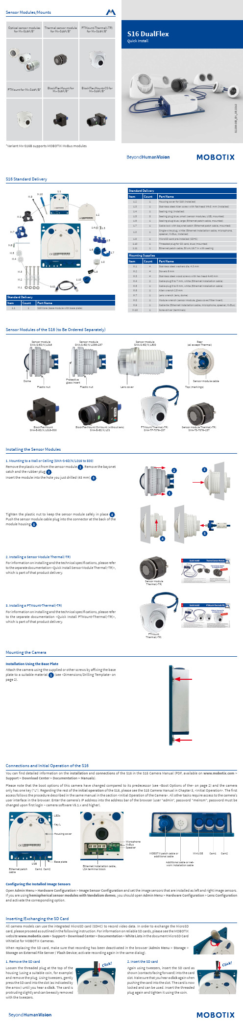
32.836-005_E N _05/2018S16 DualFlexQuick Install1.11.111.71.61.31.41.101.91.21.5M.6M.3M.2M.1M.7M.8M.5M.4M.10M.9Standard Delivery CountPart Name1S16 Core (base module with base plate)Protective glass insertPlastic nutSMA-S-6D/N/L036–237Lens coverSMA-S-6D/N/L500Top (markings)Sensor module cable SMA-S-6D/N/L016BlockFlexMount CS-Mount (without lens)Sensor module Thermal(-TR)BlockFlexMount PTMount Thermal(-TR) of the S16 in the S15 Camera Manual (PDF, available on Please note that the boot options of this camera have changed compared to its predecessor (see «Boot Options of the» on page 2) and the camera of the S16, please see the S15 Camera Manual in Chapter 3, «Initial Operation». The first access follows the procedure described in the same manual in the section «Initial Operation of the Camera». All other tasks require access to the camera’s user interface in the browser. Enter the camera’s IP address into the address bar of the browser (user "admin", password "meinsm"; password must be LCam1 Cam2MiniUSBMOBOTIX patch cable oradditional cable12345Sensor module Thermal(-TR)PTMount Thermal(-TR)Cl i c k !C l i c k !Sensor Modules/MountsOptical sensor modulesfor Mx-S16A/B *Thermal sensor modulefor Mx-S16A/B *PTMount-Thermal(-TR)for Mx-S16A/B PTMount for Mx-S16A/B BlockFlexMount forMx-S16A/B *BlockFlexMount-CS forMx-S16A/B *Variant Mx-S16B supports MOBOTIXFurther information on :Products > Outdoor Cameras > S16 DualFlexSupport > Download Center > Documentation > Certificates & Declarations of ConformityMOBOTIX, the MX logo, MxPEG and MxActivitySensor are trademarks of MOBOTIX AG registered in the Euro -pean Union, the U.S.A., and other countries • Information subject to change without notice • MOBOTIX does not assume any liability for technical or editorial errors or omissions contained herein • All rights reserved • © MOBOTIX AG 2017Boot Options of the S16By default, the camera starts as DHCP client and automatically tries to get an IP address from a DHCP server. To start the camera in a mode different The red LED lights up 5 to 10 seconds after establishing the power supply and will stay on for 10 seconds. Briefly press the key L indicated by the red circle in the figure. The camera enters the boot menu, ready for selecting The LED now flashes once and repeats the flash signal after pausing for one second (the number of flashesL130 m m /5.12 i n110 m m /4.33 i n100 m m /3.94 i n8.5 m m / 0.33 i n115 mm/4.53 in 100 mm/3.94 in100 mm/3.94 inDia. 5.50 mm/0.22 inManuals and drilling templates: > Support > Download Center > Documenta-tion > Manuals > S16 DualFlexDualMount (accessory)SurroundMount (accessory)HaloMount (accessory)SpeakerMount (accessory)PTMount (accessory)§。
浪潮英信 NP3020M4单路入门级服务器 产品说明书

浪潮英信服务器NP3020M4
1.产品概述
浪潮英信NP3020M4是一款专为中小型应用设计的单路入门级
服务器产品,采用全新的平台架构,可从容的应对各种新业务带来
的压力,同时还具有出色的扩展性,能够伴随着业务的增长而增长。
针对中小型应用的特点,NP3020M4具有出色的静音和低辐射设计,
更适合办公室环境使用,是中小型信息化建设中入门级服务器的首
选。
2.产品特性
2.1 支持英特尔最新处理器
支持英特尔最新Xeon E3-1200 v5系列处理器,采用最新Skylake微架构,相比与上一代平台产品性能急剧上升,带来更少的延迟和更高计算性能。
2.2 服务器级别的数据保护
采用支持纠错代码(ECC)的内存,提供比台式机更高水平的数据完整性、可靠性和系统正常运行时间,有效提供数据容错功能,降低系统宕机概率,从容面对不断上涨的业务。
2.3 超低噪音设计
良好的散热设计,更好的保证机箱内部气流的通畅,确保关键部件正常工作,避免因局部散热不利造成的系统宕机隐患。
360°静音设计,通过风扇及机箱的优化设计削弱噪音源,智能调控散热能力,从而大幅降低系统噪音,人性化设计全面贯穿健康理念。
2.4 服务器级别的I/O扩展
多达4个PCI扩展槽,全面支持高速PCIe x16,保护用户现有的IT设备投资,使用户短期的投资获得长期的超值回报。
2.5 强大的存储空间
拥有4块硬盘的扩展空间,可选SATA、SAS、SSD存储配置,为客户提供更灵活的数据存储选择,并提供充足的未来扩展空间。
3.产品规格。
IBM Flex System EN2024 4端口1Gb以太网适配器说明书
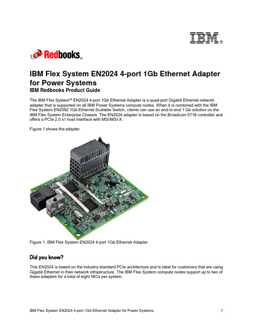
®IBM Flex System EN2024 4-port 1Gb Ethernet Adapter for Power SystemsIBM Redbooks Product GuideThe IBM Flex System™ EN2024 4-port 1Gb Ethernet Adapter is a quad-port Gigabit Ethernet network adapter that is supported on all IBM Power Systems compute nodes. When it is combined with the IBM Flex System EN2092 1Gb Ethernet Scalable Switch, clients can use an end-to-end 1 Gb solution on the IBM Flex System Enterprise Chassis. The EN2024 adapter is based on the Broadcom 5718 controller and offers a PCIe 2.0 x1 host interface with MSI/MSI-X.Figure 1 shows the adapter.Figure 1. IBM Flex System EN2024 4-port 1Gb Ethernet AdapterDid you know?This EN2024 is based on the industry-standard PCIe architecture and is ideal for customers that are using Gigabit Ethernet in their network infrastructure. The IBM Flex System compute nodes support up to two of these adapters for a total of eight NICs per system.Part number informationThe following table lists the ordering part number and feature code for the adapter.Table 1. Ordering part number and feature codeDescription Feature code(e-config)IBM Flex System EN2024 4-port 1Gb Ethernet Adapter1763The EN2024 4-port 1Gb Ethernet Adapter part number includes the following items: One adapter●Documentation CD●Important Notices flyer●FeaturesThe IBM Flex System EN2024 4-port 1Gb Ethernet Adapter has the following features: Dual Broadcom BCM5718 ASICs●Quad-port Gigabit 1000BASE-X interface●Two PCI Express 2.0 x1 host interfaces, one per ASIC●Full-duplex (FDX) capability, which enables simultaneous transmission and reception of data on the ●Ethernet networkMSI and MSI-X capabilities, up to 17 MSI-X vectors●A total of 17 receive queues and 16 transmit queues●A total of 17 MSI-X vectors that support per-queue interrupt to host●Function Level Reset (FLR)●ECC error detection and correction on internal SRAM●TCP, IP, and UDP checksum offload●Large Send offload, TCP segmentation offload●Receive-side scaling●Virtual LANs (VLANs): IEEE 802.1q VLAN tagging●Jumbo frames (9 KB)●IEEE 802.3x flow control●Statistic gathering (SNMP MIB II, Ethernet-like MIB [IEEE 802.3x, Clause 30])●Comprehensive diagnostic and configuration software suite●ACPI 1.1a-compliant: multiple power modes●Wake-on-LAN (WOL) support●Preboot Execution Environment (PXE) support●RoHS-compliant●Supported serversThe following table lists the IBM Flex System compute nodes that support the adapters.Table 2. Supported serversFor more information about the expansion cards that are supported by each blade server type, see this IBM® ServerProven website:/servers/eserver/serverproven/compat/us/I/O adapter cards are installed in the slot in supported servers (such as the x240) as shown in the following figure.Figure 2. Location of the I/O adapter slots in the IBM Flex System p270 Compute NodeSupported I/O modulesThese adapters can be installed in any I/O adapter slot of a supported IBM Flex System compute node. One or two compatible 1 Gb or 10 Gb I/O modules must be installed in the corresponding I/O bays in the chassis. The following table lists the switches that are supported. When connected to the 10 Gb switch or pass-thru module, the internal switch ports operate at 1 Gb speeds.To maximize the number of usable adapter ports, you might also need to order switch upgrades to enable morel ports as listed in the table. Alternatively, for CN4093, EN4093R, and SI4093 switches, you can use Flexible Port Mapping, which is a new feature of Networking OS 7.8 that allows you to minimize the number of upgrades needed. For more information, see the Product Guides for the switches that are available at this website:/portals/puresystems?Open&page=pg&cat=switchesThe table also specifies how many ports of the adapter are supported after the indicated upgrades are applied. Switches should be installed in pairs to maximize the number of ports enabled and to provide redundant network connections.Table 3. I/O modules and upgrades for use with the EN2024 4-port 1Gb Ethernet AdapterDescription Featurecode(e-config)Port count (per pairof switches)*1 Gb switchesIBM Flex System EN2092 1Gb Ethernet Scalable Switch + EN2092 1Gb Ethernet Scalable Switch (Upgrade 1) 35983594410 Gb switchesIBM Flex System Fabric CN4093 10Gb Converged Scalable Switch + CN4093 10Gb Converged Scalable Switch (Upgrade 1) ESW2ESU14IBM Flex System Fabric EN4093R 10Gb Scalable Switch + EN4093 10Gb Scalable Switch (Upgrade 1)ESW735964IBM Flex System Fabric EN4093 10Gb Scalable Switch + EN4093 10Gb Scalable Switch (Upgrade 1)359335964IBM Flex System EN4091 10Gb Ethernet Pass-thru37002IBM Flex System Fabric SI4093 System Interconnect Module + SI4093 System Interconnect Module (Upgrade 1)ESWAESW84IBM Flex System EN4023 10Gb Scalable Switch+ IBM Flex System EN4023 10Gb Scalable Switch (Upgrade 1) or Flex System EN4023 10Gb Scalable Switch (Upgrade 2)ESWDESWEESWF4Cisco Nexus B22 Fabric Extender for IBM IBM Flex System ESWB2* This column indicates the number of adapter ports that are active if indicated upgrades are installed. The adapter does not support the IBM Flex System EN6131 40Gb Ethernet Switch I/O module.The following table shows the connections between adapters that are installed in the compute nodes to the switch bays in the chassis.Table 4. Adapter to I/O bay correspondenceI/O adapter slot in the serverPort on the adapter Corresponding I/O module bay in the chassis Port 1Module bay 1Port 2Module bay 2Port 3*Module bay 1Slot 1Port 4*Module bay 2Port 1Module bay 3Port 2Module bay 4Port 3*Module bay 3Slot 2Port 4*Module bay 4Port 1Module bay 1Port 2Module bay 2Port 3*Module bay 1Slot 3(full-wide compute nodes only)Port 4*Module bay 2Port 1Module bay 3Port 2Module bay 4Port 3*Module bay 3Slot 4(full-wide compute nodes only)Port 4*Module bay 4* Ports 3 and 4 require Upgrade 1 of the EN2092 1Gb or EN4093 10Gb switch. The EN4091 Pass-thru only supports ports 1 and 2 (and only when two I/O modules are installed).The connections between the adapters that are installed in the compute nodes to the switch bays in the chassis are shown in the following figure. The figure shows half-wide servers, such as the p270 with two adapters.Figure 3. Logical layout of the interconnects between I/O adapters and I/O modulesOperating system supportThe IBM Flex System EN2024 4-port 1Gb Ethernet Adapter supports the following operating systems: AIX Version 6.1●AIX Version 7.1●IBM i 6.1●IBM Virtual I/O Server●Red Hat Enterprise Linux 6 for IBM POWER●SUSE LINUX Enterprise Server 11 for IBM POWER●Support for operating systems is based on the combination of the expansion card and the blade server on which it is installed. See the IBM ServerProven website for the latest information about the specific versions and service packs supported. Select the blade server, and then select the expansion card to see the supported operating systems: /systems/info/x86servers/serverproven/compat/us/WarrantyThere is a 1-year, customer-replaceable unit (CRU) limited warranty. When installed in a server, these adapters assume your system’s base warranty and any IBM ServicePac® upgrade.Physical specificationsThe adapter features the following dimensions and weight:Width: 100 mm (3.9 inches)●Depth: 80 mm (3.1 inches)●Weight: 13 g (0.3 lb)●The adapter features the following shipping dimensions and weight (approximate):Height: 58 mm (2.3 in)●Width: 229 mm (9.0 in)●Depth: 208 mm (8.2 in)●Weight: 0.4 kg (0.89 lb)●Regulatory complianceThe adapter conforms to the following standards:United States FCC 47 CFR Part 15, Subpart B, ANSI C63.4 (2003), Class A●United States UL 60950-1, Second Edition●IEC/EN 60950-1, Second Edition●FCC - Verified to comply with Part 15 of the FCC Rules, Class A●Canada ICES-003, issue 4, Class A●UL/IEC 60950-1●CSA C22.2 No. 60950-1-03●Japan VCCI, Class A●Australia/New Zealand AS/NZS CISPR 22:2006, Class A●IEC 60950-1(CB Certificate and CB Test Report)●Taiwan BSMI CNS13438, Class A●Korea KN22, Class A; KN24●Russia/GOST ME01, IEC-60950-1, GOST R 51318.22-99, GOST R 51318.24-99, GOST R●51317.3.2-2006, GOST R 51317.3.3-99IEC 60950-1 (CB Certificate and CB Test Report)●CE Mark (EN55022 Class A, EN60950-1, EN55024, EN61000-3-2, EN61000-3-3)●CISPR 22, Class A●Popular configurationsThe adapters can be used in various configurations. The following figure shows EN2024 4-port 1Gb Ethernet Adapters that are installed in both slots of the p270 (a model without the Embedded 10Gb Virtual Fabric Adapter), which in turn is installed in the chassis. The chassis also has four IBM Flex SystemEN2092 1Gb Ethernet Scalable Switches, each with Upgrade 1 installed to enable 28 internal ports. Figure 4. Example configurationThe following table lists the parts that are used in the configuration.Table 5. Components used when connecting the adapter to the 10 GbE switchesDescription Quantity Machine type /Feature Code7954-24X IBM Flex System p270 or other supported server 1 to 14 1763IBM Flex System EN2024 4-port 1Gb Ethernet Adapter 2 per server 7893-92X IBM Flex System Enterprise Chassis13598IBM Flex System EN2092 1Gb Ethernet Scalable Switch 43594IBM Flex System EN2092 1Gb Ethernet Scalable Switch (Upgrade 1)4 Related publicationsFor more information, see the following resources:Product Guides for all Flex System switches:●/portals/flexsystem?Open&page=pg&cat=switchesProduct Guides for Flex System compute nodes:●/portals/flexsystem?Open&page=pg&cat=nodesIBM Redbooks® publication IBM Flex System Products and Technology for Power Systems:●/abstracts/sg248256.htmlIBM Redbooks Product Guides for Flex System servers and options:●/portals/flexsystem?Open&page=pgbycatIBM Configurator for e-business (e-config):●/services/econfig/ServerProven for Flex System:●/systems/info/x86servers/serverproven/compat/us/flexsystems.htmlNoticesThis information was developed for products and services offered in the U.S.A.IBM may not offer the products, services, or features discussed in this document in other countries. Consult your local IBM representative for information on the products and services currently available in your area. Any reference to an IBM product, program, or service is not intended to state or imply that only that IBM product, program, or service may be used. Any functionally equivalent product, program, or service that does not infringe any IBM intellectual property right may be used instead. However, it is the user's responsibility to evaluate and verify the operation of any non-IBM product, program, or service. IBM may have patents or pending patent applications covering subject matter described in this document. The furnishing of this document does not give you any license to these patents. You can send license inquiries, in writing, to:IBM Director of Licensing, IBM Corporation, North Castle Drive, Armonk, NY 10504-1785 U.S.A.The following paragraph does not apply to the United Kingdom or any other country where such provisions are inconsistent with local law: INTERNATIONAL BUSINESS MACHINES CORPORATION PROVIDES THIS PUBLICATION "AS IS" WITHOUT WARRANTY OF ANY KIND, EITHER EXPRESS OR IMPLIED, INCLUDING, BUT NOT LIMITED TO, THE IMPLIED WARRANTIES OF NON-INFRINGEMENT, MERCHANTABILITY OR FITNESS FOR A PARTICULAR PURPOSE. Some states do not allow disclaimer of express or implied warranties in certain transactions, therefore, this statement may not apply to you. This information could include technical inaccuracies or typographical errors. Changes are periodically made to the information herein; these changes will be incorporated in new editions of the publication. IBM may make improvements and/or changes in the product(s) and/or the program(s) described in this publication at any time without notice.Any references in this information to non-IBM Web sites are provided for convenience only and do not in any manner serve as an endorsement of those Web sites. The materials at those Web sites are not part of the materials for this IBM product and use of those Web sites is at your own risk.IBM may use or distribute any of the information you supply in any way it believes appropriate without incurring any obligation to you. Information concerningnon-IBM products was obtained from the suppliers of those products, their published announcements or other publicly available sources. IBM has not tested those products and cannot confirm the accuracy of performance, compatibility or any other claims related to non-IBM products. Questions on the capabilities of non-IBM products should be addressed to the suppliers of those products. This information contains examples of data and reports used in daily business operations. To illustrate them as completely as possible, the examples include the names of individuals, companies, brands, and products. All of these names are fictitious and any similarity to the names and addresses used by an actual business enterprise is entirely coincidental.Any performance data contained herein was determined in a controlled environment. Therefore, the results obtained in other operating environments may vary significantly. Some measurements may have been made on development-level systems and there is no guarantee that these measurements will be the same on generally available systems. Furthermore, some measurement may have been estimated through extrapolation. Actual results may vary. Users of this document should verify the applicable data for their specific environment. COPYRIGHT LICENSE:This information contains sample application programs in source language, which illustrate programming techniques on various operating platforms. You may copy, modify, and distribute these sample programs in any form without payment to IBM, for the purposes of developing, using, marketing or distributing application programs conforming to the application programming interface for the operating platform for which the sample programs are written. These examples have not been thoroughly tested under all conditions. IBM, therefore, cannot guarantee or imply reliability, serviceability, or function of these programs.© Copyright International Business Machines Corporation 2014. All rights reserved.Note to U.S. Government Users Restricted Rights -- Use, duplication or disclosure restricted byGSA ADP Schedule Contract with IBM Corp.This document was created or updated on December 12, 2014.Send us your comments in one of the following ways:Use the online Contact us review form found at:●/redbooksSend your comments in an e-mail to:●***************.comMail your comments to:●IBM Corporation, International Technical Support OrganizationDept. HYTD Mail Station P0992455 South RoadPoughkeepsie, NY 12601-5400 U.S.A.This document is available online at /redbooks/abstracts/tips1243.html . TrademarksIBM, the IBM logo, and are trademarks or registered trademarks of International Business Machines Corporation in the United States, other countries, or both. These and other IBM trademarked terms are marked on their first occurrence in this information with the appropriate symbol (® or ™), indicating US registered or common law trademarks owned by IBM at the time this information was published. Such trademarks may also be registered or common law trademarks in other countries. A current list of IBM trademarks is available on the Web at/legal/copytrade.shtmlThe following terms are trademarks of the International Business Machines Corporation in the United States, other countries, or both:IBM®Power Systems™Redbooks®Redbooks (logo)®The following terms are trademarks of other companies:Intel, Intel logo, Intel Inside logo, and Intel Centrino logo are trademarks or registered trademarks of Intel Corporation or its subsidiaries in the United States and other countries.Java and all Java-based trademarks are trademarks of Sun Microsystems, Inc. in the United States, other countries, or both.Other company, product, or service names may be trademarks or service marks of others.IBM Flex System EN2024 4-port 1Gb Ethernet Adapter for Power Systems11。
FLEX SYSTEM EN2092 1GB ETHERNET调试文档
[FLEX SYSTEM EN2092 1GB ETHERNET调试文档] LENOVO FLEX SYSTEM EN2092 1GB ETHERNET SCALABLE SWITCH FOR VMWARELYDH | 2016年8月18日目录一、网络拓扑图 (2)二、Lenovo_Flex_System_x240刀片服务器网络说明 (2)三、刀箱以太网交换机调试 (3)3.1、刀箱交换机基础信息 (3)3.2、刀箱交换机登录 (3)3.2、刀箱交换机万兆口级联 (4)3.3、划分VLAN (6)3.4、将端口划分到VLAN (6)3.5、为VMware vSphere划分生产网络(trunk) (7)四、应用保存配置 (8)连接说明:在IE浏览器中输入I/O模块1的登录ip地址:https://192.168.70.120,跳转到登录页面:输入账号、密码即可登录到调试界面:3.2、刀箱交换机万兆口级联刀箱交换机的EXT21、EXT22、EXT23、EXT24端口为万兆以太网口;本次使用EXT21、EXT22端口做级联端口。
A.首先配置EXT21和EXT22端口的属性,使其可以做级联:点击“Cconfigure”,选择“SwitchPort”,点击蓝色的”EXT21”,配置EXT21端口属性将“VLAN Tragging”和“PVID Tragging”属性设置为”Enable”,然后在页面底部,选择“submit”提交修改以同样的方式修改EXT22端口的属性。
B.划分Trunck组将EXT21和EXT22划分到一个Trunck级联组:选择”Layer2“打开子目录,选择”Trunk Groups“,然后选择”1“,开始配置TRUNK Group组将”Trunk State”设置为Enable,将”Ports Available”下的EXT21和EXT22 ADD 到”Ports added to Trunk”页框下,然后“Submit”提交修改至此,级联端口以及划分完毕,剩余的工作就是将EXT22和EXT23划分到各个VLAN中,这样做,等同于允许某些VLAN通过TRUNK口。
KDS USB FW Update User Manual
111-38-URM-011KDS USB FW UpdateUser ManualKDS USB FW Update 111-38-URM-011Table of Contents1. Introduction (3)2. Process under Microsoft Windows (4)3. Process under Mac OS (5)KDS USB FW Update 111-38-URM-0111. IntroductionThe Epson Kitchen Display System (henceforth KDS) is preferably updated using the KDS Utility. However, an alternate update method using a USB flash drive can be employed as fallback if required, and is typically faster than with the KDS Utility, albeit at the cost of losing any configuration from the KDs device. This document describes the typical process to set up a USB flash drive for the firmware update.The same firmware update process is used for printers and controllers (henceforth called display box). Once set up, the USB flash drive can be used to sequentially update multiple devices.IMPORTANT NOTES:i. Before you proceed, note that updating the KDS using this method erases allconfiguration from the target device(s). The KDS Utility may be used to re-configure the system.ii. There are certain flash drives that may not work with this method and would fail the update process verification step in the procedures. Some models tested include:a. Kingston DataTraveler 8GB/16GBb. Transcend JetFlash V70 16GBc. Axiom Stealth 2 USBFD2 2GBd. SanDisk Cruzer Dial USB 16GBe. Misc. brands like AData, Samsung, Verbatim, Sony etc. USB 2.0 flash drivesKDS USB FW Update 111-38-URM-0112. Process under Microsoft WindowsThe following process has been verified under Microsoft Windows 7 and Windows 10. Most failures with the method can be attributed to user permissions (inability to modify USB flash drive) incompatible or corrupted USB flash drives.Here are the basic instructions for flashing the printer/display box FW:1. Get a USB flash drive of 1GB or more with no contents you care about, as everything on it will beerased.2. Plug the USB flash drive into a Windows PC.3. Run dd_win.exe (provided in the firmware update package)o Click on “File select…” and browse to the file “usb_boot_image_v26.ubi”o Click on “Drive select…” and specify the drive letter of the USB sticko Hit 'Run' and wait until completed.4. ***IMPORTANT*** Safely eject the USB flash drive from Windows, then unplug it, wait a fewseconds, then plug it back in again.5. Unzip the “KDS Image.zip” file onto the USB flash drive. The final layout of the USB stick should be:\|- autooperation|- uImage|- BOOT.BIN|- images\|-- control.tar.gz|-- hibdrv|-- hibernation|-- hibernationinfo|-- rootfs|-- uImage|-- writable-region6. Eject the USB stick from the PC again.7. Label the USB stick with ‘KDS Image’ to indicate what image is on it in case it is requ ired for otherdisplay boxes/printers or in future.Follow these instructions for each printer/display box that needs to be updated:1. With the printer/display box turned off, plug the USB flash drive into the Interface card at the back.2. Use a pen or paper clip to press the button on the BACK of the printer/display box, and keep itpressed while turning the board on. Keep holding the button down for three or four seconds until the LED near the button goes out.3. The LED light will then show orange for about 45 seconds, and then green for about 5 seconds, thenflash orange for about 60 seconds. Once the FW update is complete, the LED will flash green.4. Turn off the printer.5. Remove the USB flash drive from the back.6. Turn the printer/display box back on and wait for it to boot up; the LED on the back turns solid green.The KDS splash screen will show the new FW version on the attached monitor.7. The system should be ready to go.KDS USB FW Update 111-38-URM-0113. Process under Mac OSThe following process has been verified under Mac OS 10 and 11. Most failures with the method can be attributed to user permissions (inability to modify USB flash drive) incompatible or corrupted USB flash drives.Here are the basic instructions for flashing the printer/display box FW:1. Save the firmware update package (which includes the file usb_boot_image_v26.ubi) in the Desktopor Downloads folder.2. Get a USB flash drive of 1GB or more with no contents you care about, as everything on it will beerased. Do NOT plug it in yet.3. On the Mac, open a new terminal (iTerm).4. Type the command “diskutil list”to get the current list of devices.5. Now plug the USB flash drive into the Mac.6. Type the command “diskutil list”again and note the additional device, which is the USB flashdrive (e.g. /dev/disk2).7. Type the command “diskutil unmountDisk /dev/diskX”, where X is the number from Step 5.8. Type the following command:sudo dd if=$(find ~ -name usb_boot_image_v26.ubi | head -n 1) of=/dev/diskX bs=1m(again, substitute the X in the command with the number you learned from Step 5.)Please note:i. The command above will ask for the user (or administrator) password once; this is normal.ii. The command, when run for the first time, will trigger several pop-up dialogs requesting access to some folders. See Figure 3.1.iii. The command will output several lines with the text “Operation not permitted” when trying to search certain inaccessible folders; this is normal.Figure 3.1: Mac OS pop-ups requesting user permission to access some folders.(c ontinued…)KDS USB FW Update 111-38-URM-0119. ***IMPORTANT*** Safely eject the USB stick from the Mac, then unplug it, wait a fewseconds, then plug it back in again.10. Unzip the KDS Image.zip file into USB stick. This means the final layout for the USB stick should be:\|- autooperation|- uImage|- BOOT.BIN|- images\|-- control.tar.gz|-- hibdrv|-- hibernation|-- hibernationinfo|-- rootfs|-- uImage|-- writable-region11. Eject the USB stick from the Mac again.12. Label the USB stick with ‘KDS Image’ to indicate what image is on it in case it is required for otherdisplay boxes/printers or in future.Follow these instructions for each printer/display box that needs to be updated:1. With the printer/display box turned off, plug the USB flash drive into the Interface card at the back.2. Use a pen or paper clip to press the button on the BACK of the printer/display box, and keep itpressed while turning the board on. Keep holding the button down for three or four seconds until the LED near the button goes out.3. The LED light will then show orange for about 45 seconds, and then green for about 5 seconds, thenflash orange for about 60 seconds. Once the FW update is complete, the LED will flash green.4. Turn off the printer.5. Remove the USB flash drive from the back.6. Turn the printer/display box back on and wait for it to boot up; the LED on the back turns solid green.The KDS splash screen will show the new FW version on the attached monitor.7. The system should be ready to go.KDS USB FW Update 111-38-URM-011This page intentionally left blank.KDS USB FW Update 111-38-URM-011。
- 1、下载文档前请自行甄别文档内容的完整性,平台不提供额外的编辑、内容补充、找答案等附加服务。
- 2、"仅部分预览"的文档,不可在线预览部分如存在完整性等问题,可反馈申请退款(可完整预览的文档不适用该条件!)。
- 3、如文档侵犯您的权益,请联系客服反馈,我们会尽快为您处理(人工客服工作时间:9:00-18:30)。
RT-flex Comp. & SystemsRT-flex TrainingMech. Components & Hydraulic systems RT-flex &(RT-flex Specific Parts only)Chapter 20RT-flex Comp. & Systems RT-flex specific parts onlyWECS-9520, E 95Cylinder ElectronicUnit Terminal boxesE95Supply unitRail Unit(s)Automatic filterWECS-9520,E 90 Shipyard Interface Box (SIB) on the free endE90WECS-9520, E 95Cylinder ElectronicUnit Terminal boxesE95Supply unitRail Unit(s)Automatic filterWECS-9520,E 90 Shipyard Interface Box (SIB) on the free endE90WECS-9520, E 95Cylinder Electronic Unit Terminal boxes E95Supply unitRail Unit(s)Automatic filterWECS-9520,E 90 ShipyardInterface Box (SIB)on the free end E90WECS-9520, E95Cylinder Electronic Unit Terminal boxes E95Supply unitControl oil PumpsAutomatic filterWECS-9520,E90 Shipyard Interface Box (SIB)or at the free end (smaller engines) E90 ( )Rail Unit(s)6 µm 36 mThe filter "sludge" goes back to the crankcase.“ ”A)B) (0.35 bar)“ ”“ ” “ ”Single lobe drive“ ”( )RT-flex60C(3-lobe cams)“ ”( )3-lobe cams Supply unit gearwheelServo oilpump drivegearwheeland pinions2nd intermediateGearwheelCamshaft bearingCoversDrawn for Size 44Fuel side :(600 -900 bar) WECS-9520Servo oil side :Dynex ~100-200 barServo oil PumpsFuel PumpsEl. ActuatorsRT-flex60RT-flex58TFuel pumpsServo oil pumps“Bosch”)Fuel intermediateAccumulatorServo oil collectorBlock Servo oil outlet to railFuel outletto rail2nd intermediate GearwheelElectric actuatorsFuel pressure retaining valveShutdown &overpressureregulating valve&Fuel drainFuel return tomixing tankShutdown solenoid valveFuel inlet from booster unitIntermediate accumulator with two safety valves (1’250 bar). 1’250 barFuel pumps :“jerk-type fuel pumps”/Regulating rackBuffer spaceNon return valvePump plunger Pump cylinder Compression springRoller guideLower housingUpper housingPump coverRegulating sleeveRollerPlunger position at regulating linkage position:Pos : 0 No delivery 0 Pos : 5Half delivery50%Pos : 10Full delivery100%Local position indication (0-10).No load indicator !! 0-10Torsional springs Fork leverAdditional spring to push the rack, in case of failure, to full positionRT-flex Comp. & SystemsFuel Overpressure Regulating Valve Array Fuel overpressure regulating valve:~1’050 bar(Knurled screw)(Shims)1’050 bar ( for RT-flex84T-D and96C-B see Service Letter RT-flex-07/07).500 bar(piston)Shutdown Solenoid Valvesinter filter Lever for manual de-pressurising for mainte-nancePistonRT-flex Comp. & Systems Servo oil pumps arrangement :230barSupply Unit, Servo Oil (96C)DynexBosch ( )Collector BlockOil supplyNon return valves at each inletSafety valveHigh pressure PipesServo oil PumpsFlow sensorSuction portCompensator valve with solenoid HP-outlet()(Inch-type ormetric thread)Function of pressure regulation valve (“compensator valve”) of Dynex pumpBosch230 barSwashplate angle encoder Proportional valve position TransmitterProportional valve solenoid-valvesHigh pressureoutlet Anti cavitation inlet (from servo oil main supply pipe) ( )Non return Valve / anti cavitation port /Control oil inletLeak oil returnCase drainoil inletProportional ValveHP-outlet pressure TransmitterVisual indicationRT-flex Comp. & Systems Servo Oil Pump “Bosch”Bosch-Rexroth -WECS()B,B1Pressure Port( )SAE 1 1/2 "SB Anti Cavitation Port( )SAE 2 "S Suction Port ( )SAE 3 "P,SP Control Pressure Port( )M18x1.5Rkv Pilot Fluid Drain( )M22x1.5R(L)Return (Aeration)( )M42x22 Pressure retaining valves 2 Overpressure relief valvesHP-Inlets from pumps2 (3) HP-outlets for double wall pipes -> control oil rails2 (3)3 shut of valves for outlets3Pressure transmitter for leak detection (signal to Alarm System)( )Drain valve for leakage (with orifice)“Kraus & Wimmer”“Bucher”RT-flex Comp. & Systems Service Pump RT-flex50, flex58TB/60CMK II, flex68B and flex82Size 4 7SIB (E90) Box (Size 4: 7 )WECS-9520 Cylinder-Electronic Unit boxes=>Protection barsRT-flex58T, MK I RT-flex58T, MK IIRT-flex Comp. & SystemsFuel oil railServo oil rail ICUVCUSteamRail Unit Main PartsFuel oil rail :~ 600 -800 barInjection Control Unit (ICU)Servo oil rail :6 µm ~80-190barValve Control Unit (VCU) Additional return/leakage piping : ICURT-flex Comp. & SystemsFuel oil railServo oil railICU‘sVCU’sControl oil railSteamRail Unit Main Parts (Size 4)Fuel oil rail :~ 600 -800 bar Injection Control Unit (ICU)Servo oil rail :6 µm ~80-190barValve Control Unit (VCU)Control oil rail :200 bar Additional return/leakage piping : ICURT-flex96C-BRT-flex96C-BRT-flex Comp. & Systems Fuel Rail PipeThe bore has a shape of a “peanut”.RT-flex96CConnecting piece between fuel rail and ICUICUTrace heatingServo oil railFuel oil railICUVCUFuel overpressure regulating valveServo oil return pipeFuel pressure relief valveTrace heating Servo oil railFuel oil railICUVCUServo oil return pipeFuel rail :~ 600 -900barInjectionControl Unit (ICU) ICUs WECS ICUsICUsVCUsServo oil return pipeMain bearing oil supplyControl oil supply railControl oil return railFuel railServo oil rail Servo oil rail :(6-micron)~ 80-190 barValveControl Unit / exhaust valve actuator (VCU) WECS VCUsTrace heating ICU fuel drain pipeFuel leakage drain to overflow tankSHD-valvearrangementControl oilsupply railControl oilreturn railOverpressure regulating valve。