基于ISD4004语音数据的采集与播报-翻译
ISD4004语音合成系统在铁路车辆监控中的应用

能 化 控 制 与 管理 。
【 关键词】ID 0 4 S 4 0 ;语音合成;车辆监控 【 中图分类号 】T 1 N9 2 【 文献标识码】B
p a b c r s e il n r d c d Vo c e me t a e c mb n d t g t e n r ly d b c c o ig t e S I ly a k a e p cal i t u e . e y o i e s g n s r o i e o eh ra d a e p a e a k a c r n o t P d h s r l p oo o n o told b e a r tc la d c n r l y MCU. C mbn d wi C1 4 mir c mp tr i e o i e t P 0 c o o ue , t e sae a l a e il n t h h t ts o r i y v h ce a d i f w s c n r le e u in a e r p r d a d r c r e o t x c t r ot n e o d o o e e d .
A c r i g t I D4 0 u cin , c odn o S 0 4 S fn t s o t e ad a e c ru t a d ot r e d sg s o mpe n v ie e o d n a d h h r w r ic i n s f wa e in t i lme t oc rc r ig n
【 摘 要】介绍 了应用于铁路 车辆监控 系统 中的基于 ID S删
基于ISD4004的语音录放系统
本科毕业设计(2012届)题目语音录放系统的设计学院专业班级学号学生姓名指导教师完成日期2012年5月摘要本论文主要实现语音录放系统的设计。
语音录放系统主要包括单片机控制模块、语音采集模块、语音处理模块、信号放大模块,其中单片机控制模块是整个系统设计的关键。
在语音的录放过程中,单片机通过SPI通信方式与语音模块进行通讯,来实现语音的录音与播放。
由于每段录音都对应着不同的地址,因此在播放录音时,需要发送需要播放的地址即可播放。
语音录放系统的信号处理过程主要包括语音的采集、信号的放大和语音的滤波。
语音经过驻极体传感器,即麦克风,把声波信号转换成电信号。
传感器采集的电信号进过放大电路,放大一定倍数,经滤波、耦合之后送至语音模块。
语音模块对连续变化的语音信号进行采样,抽取其中的语音信号电平,直接存储在语音芯片ISD4004中,因此使得语音自然真实。
当语音播放时,需要在语音芯片的输出段加一个带通滤波器,以滤除音频带宽以外的信号,从而减少杂音的干扰。
STC89C52单片机的程序,使用keil编译程序进行设计和调试完成,其主要功能是控制语音模块,以及液晶显示模块。
关键词:微控制器;录音放音;ISD4004;ABSTRACTThe main aim of this paper is to realize the function of voice recording and playback system. The key to the overall system design of the voice recording system which includes a single-chip control module, voice acquisition module, voice processing module, signal amplification module, is MCU control module. In the voice playback process, the microcontroller communicates through SPI communication voice module,thus realizing voice recording and playback. Each recording corresponds to a different address, so the microcontroller just need to send the address of the recording to be played for play back.The signal processing of the voice recording system includes speech acquisition, signal amplification and voice filter. Acoustic signal is converted into electrical signals through electrets sensor, which is also called microphone. The sensor signals will be amplified after flow through the amplifying circuit. Finally it will be send to voice module after filtering, coupling. Continuous acoustic signal is sampled by the voice module, which takes one of the voice signal level, directly stores it in the voice chip ISD4004, and makes speech natural and true. When the recording is played we need a band-pass filter in the voice chip output section, to filter out the signal outside the audio bandwidth thereby reducing noise. The codes of the Microcontroller STC89C52 is designed and tested by using keil compiler, whose main function is to control the voice module and LCD module.Key words:Microprocessor; V oice Recording and playing; ISD4004目录1 引言 (1)2 概述 (2)2.1 语音录放系统概述 (2)2.2 本设计方案的论证 (3)2.2.1 系统的单片机选择论证 (3)2.2.2 系统的液晶选择 (3)2.2.3 系统的滤波电路的选择 (3)2.3 研发方向和技术关键 (3)2.4 主要技术指标 (4)3硬件设计 (5)3.1 硬件的总体设计 (5)3.2驻极体传声器 (6)3.3信号放大电路 (6)3.4 语音信号功率放大电路 (8)3.5 ISD4004语音芯片介绍 (9)3.5.1 芯片性能简述和引脚图 (9)3.5.2 ISD4004芯片主要引脚描述 (10)3.5.3 SPI协议 (11)3.6滤波电路的设计与方案论证 (13)3.7 基于matlab软件对滤波前后语音的分析 (15)4软件设计 (22)4.1 总体方案 (22)4.2 程序流图 (22)4.3 模块说明 (24)4.3.1 ISD4004驱动程序 (24)4.3.2 1602液晶底层驱动 (26)4.3.3菜单选择程序 (28)4.3.4 录音函数 (29)4.3.5放音函数 (30)4.3.6 播放方式选择 (32)5制作与调试 (34)5.1 硬件电路的布线与焊接 (34)5.1.1 总体特点 (34)5.1.2 Altium designer软件画PCB (34)5.1.3焊接 (34)5.2 调试 (34)5.2.1 硬件调试 (34)5.2.2 软件调试 (35)5.3 系统的各个工作状态下实物照片图 (36)6 结论 (38)致谢 (39)参考文献 (40)附录 (41)1 引言从20世纪30年代初到50年代初,有声电影主要应用光学录音方法。
ISD4004系列录放芯片在电话查询系统中的应用
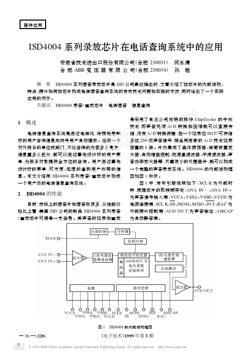
图 5 是一个用 A T89C8252 构成的 48min 语音 查询系统的实例 ,该产品已在一家公司搬迁时 ,用于 公司新电话号码的查询中 。
该 系 统 采 用 三 片 ISD4004 , 控 制 器 采 用 A T89C8252 。ISD4004 的片选信号SS由控制器的脚
36 (228)
图 1 ISD4004 的内部结构框图
《电子技术》1999 年第 5 期
ISD4004 与普通的录音/ 重放芯片相比 ,有如下 特点 :
(1) 记录的声音没有段长度的限制 ; (2) 声音的记录无需 A/ D 转换和压缩 ,放音自 然 、完美 ; (3) 快速闪存作为存储介质 ,无须电源可保存 数据长达 100 年 ,重复记录 10 000 次以上 ; (4) 内置的闪速存储器 ,记录时间长达 16min ; (5) 接口简单 , SPI 接口提供全部数据和控制 操作 ; (6) 3V 电压供电 , 待机耗 电 1μA , 放 音 耗 电 30mA ,录音耗电 25mA 。
ISD4004 可以设置放音或录音的起始地址 ,但 是无法设置放音或录音的结束地址 ,给存储器的利
图 3 SPI 的控制位示意图
《电子技术》1999 年第 5 期
(229) 37
用带来了极大的不便 。但器件提供了地址计数器指 针 ,通过读 SPI 总线的 M ISO 的寄存器的 P0~ P10 位和 EOM 位 ,就知道该信息的结束地址 ,通过查询 信息的起始地址 ,就可以唯一确定一条信息的位置 。
停止当前操 作
S TO P PO WDN
ቤተ መጻሕፍቲ ባይዱ
0 X01 X〈XXXXXXXXXXX〉
停止当前操 作并进入待 机状态
ISD4004系列语音芯片中文资料
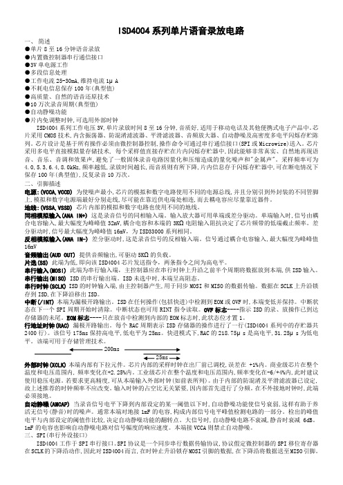
ISD4004系列单片语音录放电路一、简述●单片8至16分钟语音录放●内置微控制器串行通信接口●3V单电源工作●多段信息处理●工作电流25-30mA,维持电流1μA●不耗电信息保存100年(典型值)●高质量、自然的语音还原技术●10万次录音周期(典型值)●自动静噪功能●片内免调整时钟,可选用外部时钟ISD4004系列工作电压3V,单片录放时间8至16分钟,音质好,适用于移动电话及其他便携式电子产品中。
芯片采用CMOS技术,内含振荡器、防混淆滤波器、平滑滤波器、音频放大器、自动静噪及高密度多电平闪烁存贮陈列。
芯片设计是基于所有操作必须由微控制器控制,操作命令可通过串行通信接口(SPI或Microwire)送入。
芯片采用多电平直接模拟量存储技术, 每个采样值直接存贮在片内闪烁存贮器中,因此能够非常真实、自然地再现语音、音乐、音调和效果声,避免了一般固体录音电路因量化和压缩造成的量化噪声和"金属声"。
采样频率可为4.0,5.3,6.4,8.0kHz,频率越低,录放时间越长,而音质则有所下降,片内信息存于闪烁存贮器中,可在断电情况下保存100年(典型值),反复录音10万次。
二、引脚描述电源:(VCCA,VCCD)为使噪声最小,芯片的模拟和数字电路使用不同的电源总线,并且分别引到外封装的不同管脚上,模拟和数字电源端最好分别走线,尽可能在靠近供电端处相连,而去耦电容应尽量靠近器件。
地线:(VSSA,VSSD)芯片内部的模拟和数字电路也使用不同的地线。
同相模拟输入(ANA IN+)这是录音信号的同相输入端。
输入放大器可用单端或差分驱动。
单端输入时,信号由耦合电容输入,最大幅度为峰峰值32mV,耦合电容和本端的3KΩ电阻输入阻抗决定了芯片频带的低端截止频率。
差分驱动时,信号最大幅度为峰峰值16mV,为ISD33000系列相同。
反相模拟输入(ANA IN-)差分驱动时,这是录音信号的反相输入端。
ISD4004语音芯片在语音报站器中的应用
ISD4004 语音芯片在语音报站器中的应用 摘要ISD4004语音系列芯片是美国ISD公司推出的产品,具 有可多次重复录放、存储时间长、使用时不需扩充存储器、所需外围电路 简单等特点。
介绍了ISD4004芯片在语音报站器中的一个实际应用,并说明 了其功能和使用方法,从而使读者对ISD4004系列语音芯片的使用 有个初步的了解。
关键词 4004 单片机语音报站器 ISD4004语音芯片是由美国ISD公司推出的新产品。
关于该语音芯片的引脚说明以及内部电路等,很容易在ISD公司提 供的芯片资料中查到,笔者就不进行过多的描述,只简单地对其特点做一 介绍。
与普通的录音/重放芯片相比,ISD4004具有如下特点首先, 记录声音没有段长度限制, 并且声音记录不需要A/D转换和压缩; 其次, 将快速闪存作为存储介质,无需电源即可保存数据长达100年,重复记 录10000次以上;此外,ISD4004具有记录时间长可达16分 钟,本文采用的为8分钟的ISD4004语音芯片的优点;最后,IS D4004的开发应用具有所需外围电路简单的优点,这一点从本文介绍 的其在语音报站器中的实际应用可以体会到。
1语音报站器硬件电路设计 目前市场上流通的语音报站器,大多采用的不是ISD4004系列 的芯片,这与其刚推出不久以及价格偏高有关。
但随着ISD4004应用的增多以及价格的回落,再加上ISD4 004系列芯片本身的优点,可以相信,在语音报站器中采用ISD40 04系列语音芯片是完全可行的。
笔者设计了该装置的硬件电路,并进行了上车调试,取得了较为满意 的效果。
图 1 报站器硬件电路连接图 本文讨论的语音报站器主要是指装在车上的放音电路,不包含录音电 路。
而在实际应用中,录音电路则完成报站内容的录音工作,并收录内容 存储到语音芯片中。
本文主要结合ISD4004在放音电路中的使用介绍ISD40 04的典型应用。
本文讨论的报站器主电路主要由单片机89C52和ISD400 4构成。
基于ISD4004芯片的语音录放系统设计
基于ISD4004芯片的语音录放系统设计ANYANG INSTITUTE OF TECHNOLOGY本科毕业论文基于ISD4004芯片的语音录放系统设计The Design of Voice Recording and Playback System Based onISD4004系(院)名称:计算机科学与信息工程学院专业班级:11届网络工程学生姓名:张红红学生学号:200703050017指导教师姓名:曹领指导教师职称:讲师2011年5月毕业设计(论文)原创性声明和使用授权说明原创性声明本人郑重承诺:所呈交的毕业设计(论文),是我个人在指导教师的指导下进行的研究工作及取得的成果。
尽我所知,除文中特别加以标注和致谢的地方外,不包含其他人或组织已经发表或公布过的研究成果,也不包含我为获得安阳工学院及其它教育机构的学位或学历而使用过的材料。
对本研究提供过帮助和做出过贡献的个人或集体,均已在文中作了明确的说明并表示了谢意。
作者签名:日期:指导教师签名:日期:使用授权说明本人完全了解安阳工学院关于收集、保存、使用毕业设计(论文)的规定,即:按照学校要求提交毕业设计(论文)的印刷本和电子版本;学校有权保存毕业设计(论文)的印刷本和电子版,并提供目录检索与阅览服务;学校可以采用影印、缩印、数字化或其它复制手段保存论文;在不以赢利为目的前提下,学校可以公布论文的部分或全部内容。
作者签名:日期:目录引言 0第1章绪论 (1)1.1系统设计的意义 (1)1.2系统设计的目的 (1)1.3系统采用的实现方法 (2)第2章单片机控制技术和开发环境介绍 (3)2.189C52单片机性能和引脚介绍 (3)2.1.1概述 (3)2.1.2 AT89C52主要性能参数 (3)2.1.3引脚功能说明 (3)2.2 KEIL开发环境和建立工程 (7)2.2.1 keil简介 (7)2.2.2 Keil工程建立 (7)2.3ISD4004介绍 (10)2.3.1性能简述和引脚图 (10)2.3.2引脚描述 (10)2.4SPI(串行外设接口) (12)2.4.1协议介绍 (12)2.4.2 信息快进 (13)2.4.3上电顺序 (13)2.4.4 SPI端口的控制位 (14)2.4.5 SPI控制寄存器 (15)2.4.6时序 (16)第3章系统总体设计 (17)3.1硬件电路设计 (17)3.1.1硬件电路图 (17)3.1.2 ISD4004原理图 (17)3.2软件设计 (18)3.2.1语音芯片的内部信息寻址机制 (18)3.2.2监控ISD4004录音地址的实例 (19)3.2.3程序流程图 (20)第4章测试实例 (22)4.1测试内容 (22)4.2测试结果 (22)4.3基于ISD4004的家庭语音报警系统设计 (22)4.3.1语音录放模块设计 (23)4.3.2系统软件设计 (24)4.4基于ISD4004的红外遥控医院语音播报系统的设计 (25)4.4.1系统的硬件设计.............................................................................. 错误!未定义书签。
基于51单片机的ISD4004语音控制器

电子报/2006年/4月/23日/第015版单片机应用基于51单片机的ISD4004语音控制器成都吴圣江美国华邦公司的ISD4004系列语音芯片,应用电路简单、不怕掉电、存储量大、编程方便,适合于不同的应用场合。
该系列有4种规格的芯片,分别是8分钟、10分钟、12分钟和16分钟。
由于不同规格的芯片内部的存储器容量相同,录音时间的长短是通过降低采样频率来实现的,因此,如果需要较好的音质,则应该选用录音时间较短的产品。
该系列的语音芯片必须使用SPI接口与外部的微控制器或微处理器通信,而低档的AT89×51系列单片机没有专门的硬件SPI模块,故笔者使用软件模拟SPI的方式来控制ISD4004(下面简称ISD)。
硬件设计:考虑到该装置的操作易用性和方便性,使用了红外遥控和液晶显示来实现友好的用户交互界面。
红外遥控可以使用普通的家用遥控器,液晶部分采用Nokia的3310手机屏。
这主要是基于以下原因:普通的中文液晶显示模块价格不菲(100元以上),英文的液晶模块使用者又不大习惯,而3310液晶屏支持中文显示,价格十分便宜(成都报价仅15元),美中不足是需要自制一块液晶背光板。
语音放大部分用一片TDA2822,外围仅几个元件,十分简单。
硬件电路见图1。
控制部分:AT89S51单片机的INT0脚接一体化红外接收头的数据输出端。
当接收到红外遥控信号时,红外接收头输出一连串的高、低电平,此时单片机产生外部中断,同时结合其内部的软件定时器,分别计算红外编码高、低电平的持续时间,并以此判断红外编码,此部分在软件中有详细的注释。
读取的红外编码有4组,分别是系统码及其反码,信息码及其反码。
在INT0中断服务程序读取码值之后,将其放在一个数组中,红外码格式如图2所示。
中断服务程序将头脉冲和结束码自动丢弃。
系统码用于区分不同的遥控器,以防干扰。
3310液晶显示不是本文介绍的重点,读者也可选用其他显示方式。
由于ISD使用的是3V电源,而89551使用的是5V电源,因此在单片机的I/O口输出时,应该串10kΩ电阻后再接到ISD的SPI接口,而MISO口是由ISD输出、89S51输入的,为使89S51能准确地识别其电平,要在ISD的MISO脚加一只NPN三极管接成的反相器,向89S51的MISO 提供足够电压。
ISD4004系列器件语音拷贝系统的设计
放音时 , 遇到 E M标志时 , O 放音 自动停止 , 产生中断 ; 录 音时 , 需要向器件发送 SO T P命令 , 写入一个 E M标志 , O
结 束 录音 .
放音时 ,每播放一行语音 ,产生一个 R C周期信 A
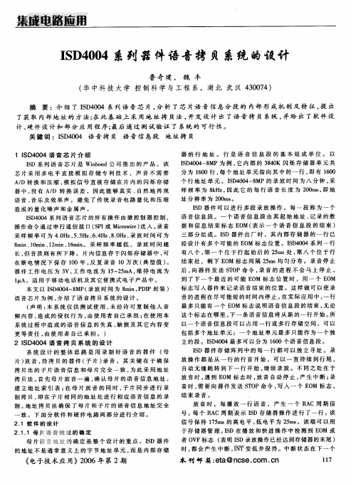
1 D 0 4语音芯片介绍 I 40 S I S D系列语音芯片是 Wi od公司推出的产品.该 nn b
芯片采用多 电平直接模拟存储专利技术 ,声音不需要
器 的行 地 址 .行 是 语 音 信 息 段 的基 本 组 成 单 位 . 以
A D转换和压缩 , / 模拟信号直接存储在片内的闪烁存储 器中, 没有 A D 转换误差 ,因此能够真实 , / 自然地再现
后, 要等待To 后器件才能停止工 sp t 作. 对于I 40-M , =0 s S 04 8 P t 5m o D To sp
( )为 了达到较好 的放音和录 3 音质量 , 录音和放音时 , 建议采用下 面 的操 作 顺序 :
放音时 :①发送 P W R P命 O EU
I 40 系列语音芯片的所有操作由微控制器控制, S 04 D 操作命令通过串行通信接 口(P 或 Mc wr) SI i i 送人. o r e 录音
采样频率可为 4O z53 z641, H , . , H , 1 8O z 录放时间可为 H . . z . 8 i,0 i,2 i,6 i.采样频率越低 ,录放时间越 mn 1mn mn mn 1 1 长, 但音质则有所下降.片内信息存于闪烁存储器中, 可 在断电情况下保存 10年 , 0 反复录音 1 0万次( 典型值 ) . 器件工作 电压为 3 工作 电流为 巧- 5 A, V, 2m 维持 电流为
- 1、下载文档前请自行甄别文档内容的完整性,平台不提供额外的编辑、内容补充、找答案等附加服务。
- 2、"仅部分预览"的文档,不可在线预览部分如存在完整性等问题,可反馈申请退款(可完整预览的文档不适用该条件!)。
- 3、如文档侵犯您的权益,请联系客服反馈,我们会尽快为您处理(人工客服工作时间:9:00-18:30)。
学号:200712020119HEBEI UNITED UNIVERSITY毕业设计翻译(汉译英)学生姓名:程英杰专业班级:07通信1班学院:信息工程学院指导教师:张涛2011年06月08日原文一、综述20世纪末,电子技术获得了飞速的发展。
在其推动下,现代电子产品几乎渗透到了社会的各个领域,有力的推动和提高了社会生产力的发展和现代信息化程度,同时也使电子产品性能进一步提升,更新换代的节奏也越来越快。
而随着我国经济建设的迅猛发展,公安、铁路、民航、金融等部门对语音记录的需求不断增长。
把语音生成技术用于工业监控系统、自动应答系统、多媒体查询系统、智能化仪表、办公自动化系统或家用电气产品中,使它们具有语音输出功能,能在适当的时候用语音实时报告系统的工作状态、警告信息、提示信息或相关的解释说明等,无疑在提高人机通信能力、减少对错误处理的遗漏、提高系统安全性能、降低人们的工作强度等方面都有极大的好处。
本设计即是出于这样目的来进行研究开发。
二、硬件设计电子录放系统可以采用PC机和嵌入式系统两种实现方式。
当使用PC机的时候,由于它的体积庞大,耗电高,造价也高,并且在某些情况下系统的稳定性得不到保证,所以用PC机实现电子录放系统,就受到了一定的限制。
而嵌入式系统体积小,供电方便,造价低,稳定性也高,所以得到了广泛的应用。
现阶段下,实现嵌入式电子录放系统主要有三种方案:通用单片机方案、DSP芯片方案和语音芯片方案。
本设计选择语音芯片方案研究。
1、语音芯片方案结构模型采用语音芯片方案实现电子录放系统,结构模型如图1所示。
图1 语音芯片方案结构模型在本方案中,控制器是整个系统的控制中心,它控制语音芯片完成特定的操作。
语音芯片是整个系统的语音数据处理中心。
录音时,语音信号经过放大后送入语音芯片进行处理,处理后的语音数据存入芯片内部存储器中;回放时,从存储器中读取语音数据,经过芯片处理后还原成语音信号,最后经功放放大后从喇叭输出。
2、语音芯片本设计选择ISD4004-16语音芯片进行研究。
ISD4004-16是美国的ISD公司推出的产品。
该芯片采用CMOS技术,内含晶体振荡器、防混叠滤波器、平滑滤波器、自动静噪、音频功率放大器及高密度多电平闪烁存储阵列等,因此只需要很少的外围器件即可构成一个完整的电子语音录放系统。
该芯片采用多电平直接模拟存储(Chip Corder)专利技术,每个采样值直接存贮在片内闪烁存储器中,语音数据不需要A/D转换和压缩,因此没有A/D转换误差,能够非常真实、自然地再现语音、音乐、音调及效果声,避免了一般固体录音电路量化和压缩造成的量化噪声和“金属声”。
该芯片工作电压3V,工作电流25~30mA,维持电流1µA。
具有SPI串行通信接口,便于和控制器通信,单片录放时间可达16分钟,其内部语音存储器共分2400行,每行占用时间长度为400ms。
程序可任选一行作为录音、放音操作的起始地址。
分段地址范围为0000H~0960H。
3、控制器单片机以其高可靠性、高性价比、低电压、低功耗等优点得到迅猛发展和大范围推广,广泛应用于工业控制系统、数据采集系统、日常消费类产品等,利用单片机实现语音录放有很大的研究和开发价值。
本设计采用AT89C51作为控制器。
AT89C51是一种带4K字节闪存可编程可擦除只读存储器的CMOS 8位微处理器。
它采用ATMEL高密度非易失存储器制造技术制造,与工业标准的MCS-51指令集和输出管脚相兼容,用来实现整个系统的功能控制,是整个电子录放系统的控制核心。
该芯片通过自身IO口虚拟SPI接口来实现对ISD4004的录音、放音、快进等功能的控制。
本设计主要分为四个模块:控制模块、录音模块、放音模块、电压模块。
各模块实现主要功能如下。
控制模块主要包括按键电路、复位电路、时钟电路。
实现功能有录音、放音、停止等,因为AT89C51不含有SPI接口因此还要模拟SPI 接口与ISD4004-16进行通信。
录音模块实现语音信号的捕获、存储。
本设计采用驻极体话筒和晶体管相结合的方法,实现对语音信号的捕获,由ISD4004-16芯片实现对语音信号的调整和存储。
放音模块实现语音信号的播放。
ISD4004-16音频输出信号比较微弱,只能驱动5KΩ的负载,本设计采用LM386对语音信号进行放大处理,输出信号推动扬声器。
电压模块实现对ISD4004-16语音芯片供电。
单片机AT89C51工作于5V,而ISD4004-16芯片工作于3V,因此需要电压转换。
本设计采用LM317实现电压的转换。
三、软件设计根据系统要实现的功能和硬件电路设计,不难设计出本系统的软件。
软件设计同样使用模块化设计思路。
设计几个供CPU访问的的功能子函数:播放子函数、停止子函数、录音子函数、快进子函数、读取当前状态和地址子函数等。
本设计中定义两个静态全局变量:rac_addr和states。
其中rac_addr为无符号整型变量,记录当前操作地址。
states为无符号的字符变量,代表ISD4004-16状态,各位定义如图2所示。
图2 states各位定义各位功能说明如下:(1)rec(states.0):rec=1表示ISD4004-16处于录音状态。
(2)play(states.1):play=1表示ISD4004-16处于放音状态。
(3)ovf(states.2):ovf=1表示ISD4004-16溢出。
(4)eom(states.3):eom=1表示ISD4004-16到达当前语音段末尾。
(5)mc(states.4):mc=1表示ISD4004-16处于快进状态。
电路上电后,程序首先完成系统的初始化,随后查询按键状态,系统进入待机状态。
如果有按键按下,则转去执行该按键所对应的工作程序。
按键包括放音键、录音键、快进键、停止键。
在待机状态下,如果放音键被按下,并且此时ISD4004-16没有处于录音和快进状态,则调用放音子程序,此时如果再次按下放音键,则系统停止放音。
如果系统自动停止放音,则ISD4004-16的中断引脚(25脚)会自动送一低电平信号。
在硬件电路设计中,该引脚与单片机的P3.2连接。
因此,会引起一次中断,在中断子程序中会判断触发中断的原因,如果是因为OVF触发中断,则重新设定起始地址,系统进入待机状态;如果是EOM触发中断,则更新当前地址,系统进入待机状态。
如果录音键被按下,并且此时ISD4004-16没有处于放音状态,则调用录音子程序,此时如果再次按下录音键,则系统停止录音,也可以不做任何操作,直到遇到OVF,自动停止录音。
如果是快进键被按下,并且此时系统处于放音状态,则调用快进子程序,从当前地址开始快进,直到遇到EOM后停止。
如果停止键被按下,则调用停止子程序,停止当前操作并掉电。
译文I. SummaryAt the end of 20th century, electronic technology has obtained a rapid development. In support of it, almost modern electronic products have penetrated into all areas of society, it effectively promotes and enhances the development of social productive forces and the extent of modern information technology, at the same time it improves the performance of electronic products, replacement of electronic products are getting faster and faster. With the rapid development of economic construction in China, Public security, railway, civil aviation, finance and other departments frequently use the voice recording. The speech generation technology for industrial monitoring systems, automatic answering systems, multimedia query systems, intelligent instrumentation, office automation systems or home electrical products make them with speech output capabilities, which can in due course, real-time report system with work status, alerts, tips or related explanation, etc. It is no doubt improve the ability of human-machine communication, reduce the omission of error handling, improve system security, reduce the intensity of people's work have great benefits. This design is to research for such purposes.II. Hardware DesignPC and embedded systems can be used to achieve electronic recording system. If you use a PC machine, because of its large size, high power consumption, high prices, and in some cases, system stability can not be guaranteed, so electronic recording and playback system based on PC is limited. Due to the small size, supply convenient, low cost, high stability of embedded systems, it has won a wide range of application. Under the present stage, realization of embedded electronic recording system has three main programmes: General SCM programme, DSP chips programme and voice chip programme. This design selects the voice chip programme.1. V oice chip programme structure modelThe structure model of electronic recording systems using voice chip is shown in Figure 1.Figure 1 Structural model of voice chip programIn this design, the controller is the control center of the whole system. It controls the voice chip to complete a specific operation. V oice chip is the data processing center of the whole system. When you record, speech signal after amplification will be processed in the voice chip, voice data which is processed will be stored in the memory chip. When you play, voice data will be read from memory, and then voice chip will process the voice data into voice signals. Finally, voice signals output from the speaker after through the amplifier.2. V oice ChipThis design choices voice chip ISD4004-16. ISD4004-16 is produced by the United States ISD Company. The CMOS-based devices include an on-chip oscillator, antialiasing filter, smoothing filter, AutoMute feature, audio amplifier, and high density, multilevel Flash storage array. Therefore, only very few external components are needed to form a complete electronic voice recording system. The chip uses multi-level direct analog storage (Chip Corder) patented technology. The speech samples are stored directly into on-chip nonvolatile memory without the digitization and compression associated with other solutions. Direct analog storage provides a natural sounding reproduction of voice, music, tones, and sound effects not available with most solid-state solutions. The ISD4004-16 ChipCorder Product provides high-quality, 3-volt, single chip record/playback solutions for 16 minute messaging applications. Operating current 25 ~ 30mA, Standby current 1µA. SPI interface is provided for ISD4004 control and addressing functions. Its internal voice memory consists of 2,400 rows, each row takes time 400ms. Program can choose a row as recording, playback start address of the operation. The range of segment addresses for 0000H~0960H.3. ControllerSCM (single-chip microcomputer) with its high reliability, high performance, low-voltage, low power consumption advantages is rapid development and wide promotion, it is widely used in industrial control systems, data collection systems, consumer products, etc, using it for voice recorders have great value in research and development. This design uses AT89C51 as the controller. The AT89C51 is a low-power, high-performance CMOS 8-bit microcomputer with 4K bytes of Flash Programmable and Erasable Read Only Memory. The device is manufactured using Atmel's high density nonvolatile memory technology and is compatible with theindustry standard MCS-51 instruction set and pinout. It is used to control the whole system functions. It is the control center of the electronic recording system. The chip through its IO ports simulates SPI interfaces to implementation on the ISD4004 features such as recording, playback, fast forward control.This design can be divided into four modules: Control module, Recording module, Playback module, V oltage module. Main functions of each module are shown as follows. Control module includes press circuit, reset circuit, clock circuit. It implements the recording, playback, stop, etc. Because there is no SPI interface, AT89C51 simulates SPI interface to communicate with the ISD4004-16. Recording module is used to capture, store voice signals, this design combines the electret microphone and transistors to capture the speech signal. ISD4004-16 is used to adjust and store the voice signals. Playback module is used to play the voice signal. ISD4004-16's audio output signal is weak. It can drive a load as small as 5KΩ. This design uses a LM386 to amplify the voice signal, amplified signal to promote the speaker. V oltage module provides for the ISD4004-16 speech chip suitable voltage. The AT89C51 operates at 5V, The ISD4004-16 chip operates at 3V, so the voltage converter is required. This design uses a LM317 to convert the voltage.III. Software DesignAccording to the functions and hardware design of the system, it is easy to design the software. Software design also uses the modular design concept. I designed several sub-functions, which are visited by CPU: Play Function, Stop Function, Recording Function, fast forward function, read the current status and address function, etc.This design defines two static global variables: rac_addr and states. Rac_addr is an unsigned integer variable, it records the address of the current operation. States is an unsigned character variable, it represents the state of ISD4004-16, the definition of each bit as shown in Figure 2.Figure 2 Definition of each bitFunction of each bit as follows:(1) rec (states.0) : If rec is equal to 1, it said ISD4004-16 in the recording state.(2) play (states.1) : If play is equal to 1, it said ISD4004-16 in the playback state.(3) ovf (states.2) : If ovf is equal to 1, it said ISD4004-16 has an overflow.(4) eom (states.3) : If eom is equal to 1, it said ISD4004-16 has reached the endof the current voice segment.(5) mc (states.4) : If mc is equal to 1, it said ISD4004-16 in the fast-forwardstate.After power on, the program first initializes the system, and then checks the status of four key, the system enters the standby state. If one key is pressed, the system will execute the corresponding program of the key. There are four key: playback key, record key, fast forward key, stop key. In standby state, if the playback key is pressed, and the ISD4004-16 is not in the state of recording and fast forward, the system calls the playback subroutine, at this point if the playback key is pressed again, the system stops the playback. If the system automatically stops the playback, the interrupt pin (25 pin) of the ISD4004-16 will automatically send a low level signal, in the design of hardware circuit, it connected with P3.2 of SCM. Therefore, it will cause an interrupt, in the interrupt subroutine. The system will determine the cause of the interrupt. If the OVF triggers the interrupt, the system will reset the start address, and then enter the standby state; if the EOM triggers the interrupt, the system will update the current address, and then enter the standby state. If the record key is pressed, and the ISD4004-16 is not in the playback state, the system calls the recording subroutine, at this point if the record key is pressed again, the system stops the recording, you can not do anything until the OVF, the system automatically stops the recording. If the fast forward key is pressed, and the ISD4004-16 is in the playback state, the system calls the fast forward subroutine, ISD4004-16 begins to fast forward from the current address until the EOM. If the stop key is pressed, the system calls the stop subroutine. ISD4004-16 stops the current operation and powers off.。