ansys.icemcfd教程
ICEMCFD基础教程
ICEMCFD基础教程ICEMCFD是一款用于计算流体力学(CFD)建模和网格生成的软件。
它是一种强大的工具,可以帮助工程师们构建复杂的模型、生成高质量网格以及预处理CFD求解器所需的输入文件。
本文将为您提供一份ICEMCFD的基础教程,帮助您快速上手使用该软件。
首先,我们需要了解ICEMCFD的基本界面和常用工具。
打开ICEMCFD 后,您将看到一个由不同工具栏、菜单和视图窗口组成的界面。
菜单栏提供了各种命令和选项,工具栏可快速访问常用工具,视图窗口用于显示模型、网格和结果。
在学习ICEMCFD之前,建议先熟悉软件的界面和各种工具。
然后,我们将学习如何进行网格划分。
在CFD模拟中,网格的质量对结果的准确性和收敛性有重要影响。
ICEMCFD提供了多种网格划分算法和优化工具,可帮助您生成高质量的网格。
您可以使用“划分”菜单中的“体格网划分”选项对几何模型进行三维网格划分。
您可以选择划分算法、设置网格大小和边界条件等。
在划分完成后,您可以使用“检查网格”工具检查网格的质量,并进行必要的优化。
最后,我们将学习如何导出网格并准备CFD求解器所需的输入文件。
完成网格划分后,您可以使用“文件”菜单中的“导出”选项导出网格。
ICEM CFD支持多种网格格式,如ANSYS Fluent、OpenFOAM和CFX等。
选择适当的网格格式并指定输出文件路径后,即可导出网格。
您还可以使用“准备”菜单中的“CFD 前处理”选项设置物理属性、边界条件和初始条件等,并生成CFD求解器所需的输入文件。
本文只介绍了ICEMCFD的基础教程,您还可以进一步探索该软件的高级功能和应用。
ICEMCFD非常灵活和强大,适用于各种工程领域的CFD建模和网格生成。
通过深入学习和实践,您可以熟练使用ICEMCFD并在工程实践中取得优秀的结果。
ICEM CFD 使用手册
信息:菜单包括几何信息、面的面积、最大截面积、曲线长度、网格信息、单 元体信息、节点信息、位置、距离、角度、变量、分区文件、网格报告。
设置:菜单包括常规、求解七、显示、选择、内存、远程、速度、重启、网格 划分。
帮助:启动帮助、启动用户指南、启动使用手册、启动安装指南、有关法律。
(a)几何菜单 几何菜单包括编辑、修改几何图形的功能。 功能及作用: 生成点、生成/修改线、生成/修改面、生成体、修改几何图形、转化图形、删除 点、删除线、删除面、删除体积点及删除实体。 (b)网格菜单 网格菜单包括 ANSYS ICEM CFD 网格工具的模块。 以下按钮可以导入不同 ANSYS ICEM CFD 支持和开发的网格划分模块。 设置全局网格尺寸、设置表面网格尺寸、设置曲线网格尺寸、创建加密区、创建 单元、表面网格、四面体、金字塔、六面体(旧界面)、六面体分区网格及拖拽网 格。 点击这些按钮调用网格工具模块。 (c)块操作菜单 创建块、分割块、合并顶点、编辑块、对应、移动顶点、块转换、编辑边、前期 网格参数、前期网格质量、块检查、删除块。 (d)编辑网格菜单 编辑网格菜单包括高级网格编辑必需的工具:粗化、平滑、合并网格。 通过这个菜单可执行的操作包括: 创建单元、创建中间节点、网格检查、计算和显示质量、平滑全局网格、平滑 六面体网格、修改网格、合并节点、分割网格、移动节点、偏移网格、转化网格、 网格类型转化、调整网格密度、重新编号网格、网格重新自适应、删除中间节点、 删除节点及删除单元。 (e)输出菜单 输出菜单通过装配求解器、写求解器输入文件、启动求解器来控制边界条件的 编辑。输出菜单包括以下几个功能键: 选择求解器、边界条件、编辑参数、写输入文件。 图标功能菜单: 打开工程、保存工程、打开几何文件、打开属性文件(定义在几何体中的边界条 件)、打开块文件、适合窗口、放大、测距离、当地坐标系、刷新。 回退:还原到上一步操作 前进:重返到下一步操作 框架显示:使几何图形显示框架状视图 阴影显示:使几何图形固体(不透明)显示
ANSYS ICEM CFD 网格划分教程2
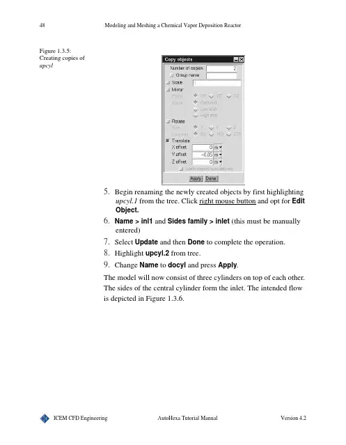
48Modeling and Meshing a Chemical Vapor Deposition ReactorFigure 1.3.5:Creating copies ofupcyl5.Begin renaming the newly created objects by first highlightingupcyl.1 from the tree. Click right mouse button and opt for EditObject. > inl1 and Sides family > inlet (this must be manuallyentered)7.Select Update and then Done to complete the operation.8.Highlight upcyl.2from tree.9.Change Name to docyl and press Apply.The model will now consist of three cylinders on top of each other.The sides of the central cylinder form the inlet. The intended flowis depicted in Figure 1.3.6.Modeling and Meshing a Chemical Vapor Deposition Reactor 49Figure 1.3.6:The intended flow forthe CVD reactor1.3.4: Creating ObjectsCreating CylindersCreate additional Cylinders by choosing Create cylinders iconfrom the top menu bar from each of following.Outduct1.Name > outduct 2.Plane > xz 3.C enter coordinates: (0.5, 0, 0.5)4.Height: 0.355.Radius: 0.156.Type > fluidNote: The changes are automatically implemented once the objectType is selected.Susceptor > susceptor2.Plane > xz3.C enter coordinates:(0.5, 0, 0.5)50Modeling and Meshing a Chemical Vapor Deposition Reactor4.Height: 0.375.Radius: 0.036.Type > hollowSusceptor Top > susc-top2.Plane > xz3.C enter coordinates: (0.5, 0.37, 0.5)4.Height: 0.035.Radius: 0.26.Type > hollowThe Cylinders created so far are shown in Figure 1.3.7.Figure 1.3.7:View of theCylinders created sofarCreating CirclesInlet1.Select Create circles icon from the top menu bar to create acircle. Select it from the tree and choose for Edit object uponclicking right mouse button. Together you get screen as shownin Figure 1.3.8.Modeling and Meshing a Chemical Vapor Deposition Reactor512.Change the Name to top-inl, signifying that this object will bethe top inlet to the reactor.3.Plane > X-Z4.C enter coordinates: (0.5, 0.5, 0.5)5.Radius: 0.036.Face family > inlet7.Press Update to complete the modifications.Figure 1.3.8:Circles edit windowwith specificationsfor top-inlNow create the remaining Circles using Create circles icon fromthe top menu barSubstrate > substrate2.Plane > X-Z3.C enter coordinates: (0.5, 0, 0.5)4.Radius: 0.25.Select Update and Done to complete the operation.Outlet > outlet52Modeling and Meshing a Chemical Vapor Deposition Reactor2.Plane > X-Z3.C enter coordinates: (0.5, 0, 0.5)4.Radius: 0.155.Face family > outlet (The user should enter this manually).6.Press Update and Done.The geometry for the CVD Reactor is now complete (Figure 1.3.9). Figure 1.3.9:Complete CVDreactor, with thecreated Circlesactivated1.3.5: Mesh GenerationCreating Cartesian Mesh1.From the AutoHexa viewing window, select Model > Gener-ate mesh to open the Mesh control window shown in Figure1.3.10. This is where all the mesh utilities are accessible.2.Select Mesh type > Cartesian to create a grid that is alignedwith the coordinate axes and quickly generated. Using thedefault parameters, select Generate mesh.Modeling and Meshing a Chemical Vapor Deposition Reactor53 Figure 1.3.10:Mesh controlwindow with thedefault parameters forthis tutorialCut planes1.Begin by Orienting the model to the Home position.2.Toggle on Mesh control > Display > Cut plane > Set position> Vertical - screen select.3.Click the left-mouse button in the center of the Domain in theAutoHexa viewing window.4.Orient > Orient positive X, and then select Mesh control >Display > Display mesh to obtain the diagram shown by Fig-ure 1.3.11.54Modeling and Meshing a Chemical Vapor Deposition ReactorFigure 1.3.11:Mesh cut plane asseen from thepositive X view usingdefault parametersLimiting Element Size1.The large element size may be controlled by adjusting the Uni-form spacing. Select Mesh control > Generate > Uniformspacing > (X count, Y count, Z count) > (50, 50, 50).2.Press Generate mesh to recalculate the mesh with the modi-fied counts. The new mesh should yield much finer mesh (i.e.50x50x50 nodes in a regular grid).3. Refer to Figure 1.3.12 to see the newly defined mesh cut plane. Figure 1.3.12:Diagram of the meshcut plane with newlyspecified X, Y, and Zcounts and higherelement count thanwhile using defaultparametersModeling and Meshing a Chemical Vapor Deposition Reactor55 Surface Elements1.To view the mesh on various parts of the reactor itself, first turnoff the Mesh control > Display > Cut plane utility for aclearer view.2.Select Display tab and turn on Surface and Current type. Thiscreates a mesh on the current object type that is selected fromthe Model menu. In this situation, the current object type isCircle. The mesh will appear as in Figure 1.3.13.Figure 1.3.13:Reactor with Surfaceelements meshdisplayed on currentobject type Circles.3.Select File > Save project from the AutoHexa viewing win-dow to save both the model and the mesh.56Modeling and Meshing a Chemical Vapor Deposition Reactor57Tutorial Example 1.4: Modeling and Meshing a LabOverview This tutorial, like the first tutorial, will focus on creating alaboratory for analyzation of the airflow through the room.Ventilation ducts on one side of the lab will supply air to the room,and a large fan on the other side of the lab will act as an outlet vent.The air will need to travel through the room, over and around thecreated obstructions, and depart through the exit vent. Thissimulation will illustrate the flow distribution inside of the room,allowing us to place the ventilation ducts at optimal locations thatare most beneficial to the occupant.Operations introduced in this example Starting a New Project•Initializing AutoHexa and beginning the projectCreating Objects•Developing the model, utilizing Domain, Hexas, Cylinders, Polygons, Circles andQuadsCopying Objects•Creating multiple entities by copy ing previously createdgeometryCreating Groups of Objects•Placing multiple objects into one Group, easing the copy ingprocessMoving Objects•Utilizing the Move function to translate geometrical entitiesinto new locationsMesh Generation•Generating Hexa mesh•Modifying the Per-object params•Generating Tetra meshConfiguration Options•Altering the Minimum object separation•Sorting the object edit lists, AlphabeticallyPrinting Screen•Doing Annotation, adding markers and getting a hardcopy ofthe modelSummary Creation•Accessing a summary of the specifications used in the cre-ation of the model1.4.1: Starting the Project1.Load ICEM CFD to open the main Mesh Editor viewingscreen, as well as the MED messages window and the Displaywindow. A File selection window should also appear, with theprompt to Select an ICEM CFD project to open,2.Type the new project name as tutorial-4 and pressAccept.3.Meshing > AutoHexa will initialize the AutoHexa modelingsystem.1.4.2: Creating ObjectsCreating the Domain1.Begin the creation of the territory of the laboratory by selectingModel > Domain from the tree.2.Resize the Domain with the following assignments: S tartpoints > (xS, yS, zS) -> (0, 0, 0) and E nd points > (xE, yE, zE)-> (10, 5, 6)3.Press Apply to activate the changes.4.Notice that the Domain is larger than the viewing window --select Orient > Isometric view to achieve a better view asshown in Figure 1.4.1.Figure 1.4.1:The modified domainCreating the HexasThe Divider1.To begin creation of the divider, select Create hexas icon fromthe top menu bar. > divider3.S tart points: (1, 0, 2.5) and E nd points: (6,4.5, 2.6)4.Select the object Type > hollow, since it is unnecessary to sim-ulate the heat transfer within the divider.Note: The changes are automatically activated when the objectType is assigned.5.Upon examination of the model, the user should notice that thedivider does not touch the wall on the low end of the X-axis.This entity may be moved by selecting Options > Interactiveediting from the tree. Toggle off Y and Z (Figure 1.4.2). Thisrestricts the motion of the divider to only along the X-axis. Figure 1.4.2:Restricting themotion of the divider6.Move the cursor to an edge of the divider. While holding theshift key down, press the middle mouse button, and drag thedivider towards the low end of the X axis, so that the divider isagainst the wall (Figure 1.4.3). The new S tart points are (0, 0,2.5), and the E nd points are (5, 4.5, 2.6).Figure 1.4.3:The new position ofthe dividerThe Worktable1.Click on Create hexas icon to create a new Hexa. > wktable3.S tart points: (6, 0, 3) and E nd points: (10, 1, 4)4.Type > solid5.Press ApplyThe Machine1. Click on Create hexas icon to create a new Hexa. > machine3.S tart points: (7, 1, 3.25) and E nd points: (10, 1.5, 3.75)4.Type > solid5.Press ApplyThe Person1.To begin creation of a person standing in front of the machine,click on Create hexas icon to create a new Hexa. > body3.S tart points: (6, 0,4.25) and E nd points: (7, 1.25, 4.5)4.Type > solid5.Press Apply6.To create the person’s head, click on Create hexas icon to cre-ate a new Hexa. > head8.S tart points: (6.25, 1.75, 4.25) and E nd points: (6.75, 2, 4.5)9.Type > solid10.Press Apply11.The person’s body and head is now complete. Refer to Figure1.4.4 to see the completed geometry created so far.Figure 1.4.4:The completegeometry created sofar1.4.3: Copying ObjectsThe Drawers1.The user will now add a file cabinet with three drawers to themodel. Click on Create hexas icon to create a new Hexa. > drawer13.S tart points: (0, 0, 0) and E nd points: (1, 0.5, 0.5)4.Type > solid5.The remaining drawers will have identical dimensions to thefirst drawer. To begin the Copy ing process, highlight drawer1from the Tree, click right mouse button on it and select Copyobject to obtain the Copy objects window, as shown in Figure1.4.5. Enter the following values.6.Number of copies > 27.Translate > Y offset > 0.5Figure 1.4.5:Copy panel8.Press Apply to create the remaining drawers. Proceed to pressDone.9.Highlight drawer1.1 from the tree and change its Name todrawer2. Select Apply when complete.10.Highlight drawer1.2 from the tree and change its Name todrawer3. Press Apply to update the change.Figure 1.4.6:The Hexas list can bemodifiedNote: Any of the three drawer s may be temporarily removed fromthe model in order to vary the conditions for the simulated flow.This is achieved by first selecting the desired object from the tree,pressing right button and then unselecting the Active option.Toggling on Active from the Inactive group from the tree, willreactivate the entity. To permanently remove an object from themodel, the user should first highlight the desired entity, and thenproceed to select Delete. This object then would show under Trashin the tree. The Undo option, however, can cancel the last action.1.4.4: Creating ObjectsCreating the PolygonThe Chair1.The user will now create a chair located next to the file cabinet.Click on Create polygons icon to create a new polygon.(Refer to Figure 1.4.7). > chair3.Plane > xy4. Height > 0.755.Highlight vert1 > (x1, y1, z1) -> (0, 1.25, 1)6.Highlight vert2 > (x2, y2, z2) -> (1.5, 0, ~)7.Highlight vert3 > (x3, y3, z3) -> (0, 0, ~)8.Type > solid9.Press Apply.Figure 1.4.7:Creation of chairusing polygons.10.Highlight vert1, as shown in Figure 1.4.711.Press Add once to create another vertex, vert2, and assign (x2,y2, z2) the values of (0.75, 0.5, ~).12.Press Add once again, creating vert3. (x3, y3, z3) > (1.5, 0.5, ~)13.To complete the chair and update the changes, select Apply.Refer to Figure 1.4.8 for the final shape of the chair.Figure 1.4.8:The final chairCreating the CylindersThe Table-legs1.Click on Create cylinders icon to create a new cylinder tobegin creation of the table-legs. > tleg13.Plane > xz4.C enter coordinates: (xC, yC, zC) > (2.25, 0, 0.5)5.Height: 0.756.Radius: 0.057.Type > solid8.To create tleg2, the user will copy tleg1. Highlight tleg1 fromthe tree,click right mouse button on it and select Copy object.This will open the Copy objects window.9.Number of copies > 110.Translate > X offset -> 1 > Y offset -> 0 > Z offset -> 011.Select Apply to create the copy, and then Done.12.Highlight tleg1.1 from the tree and change the Name to tleg2.13.Select Apply when complete with renaming the copied table-leg. Refer to Figure 1.4.9Figure 1.4.9:Geometry with Finaltable legs1.4.5: Creating Groups of Objects1.To place tleg1 and tleg2 into a group, access the tree. Clickright mouse button on Groups there and choose Create. > tlegs3.Select Orient > Orient negative Y. This will adjust the view,making tleg1 and tleg2 easily accessible.4.Right click on Groups > tlegs and choose Add > ScreenSelect.5.With the shift - left mouse button, select tleg1 and tleg2, turningthe entities red in color. Their names will appear under the treeas shown in Figure 1.4.10. Press shift - right mouse button toexit out of this selection mode.Figure 1.4.10:The tree6.To create the remaining table legs, the user should copy thenewly established group. In the tree, highlight tlegs underGroups, right click and then select Copy group. This willopen the Copy group tlegs window.7.Number of copies > 18.Translate > X offset -> 0 > Y offset -> 0 > Z offset -> 19.Press Apply to add the remaining table legs, and then Done.10.Highlight tleg1.1 from the tree, and change the Name to tleg3.Select Apply to activate the change.11.Highlight tleg2.1 from the tree, and change the Name to tleg4.Select Apply to activate the change.1.4.6: Creating ObjectsCreating the QuadsThe Table-top1.Click on Create quads icon to create a new quad. > ttop3.Plane > xz4.S tart points: (2, 0.75, 0.25) and E nd points: (3.5, ~, 1.75)5.Press Apply to complete the operationThe Inlet vents1.Click on Create quads icon to create a new quad > inl13.Plane > xy4.S tart points: (1, 0, 6) and E nd points: (4, 1, ~)5.Select this object from the tree, click right mouse button andchoose Edit object. Go to Properties and say Face family > inlet (The user will need to manually enter this assignment).6.Select Done to complete the first inlet.7.To create inl2, the user will need to copy inl1. Highlight inl1from the tree, click right mouse button and select Copy object to open the Copy objects window.8.Number of copies > 19.Translate > X offset -> 5 > Y offset -> 0 > Z offset -> 010.Select Apply > Done,11.Highlight inl1.1 and change the Name from inl1.1 to inl212.Select Apply to complete the operation. Refer to Figure 1.4.11for the completed quads.Figure 1.4.11:Geometry withcompleted quads1.4.7: Moving ObjectsThe air will enter the room via the inlet and exit via outlet fan thatwill be constructed during this section.Creating the CirclesThe Outlets1.Click on Create circles icon to create a new circle. > out13.Plane > xy4.C enter coordinates: (2.5, 2.5, 0)5.Radius: 0.756.Select this object from the tree, click right mouse button andchoose Edit object.Go to Properties and say Face family >outlet (The user will manually enter this assignment).7.Select Done to complete the outlet.8.Observing the configuration, the user should notice that out1 ispoorly situated behind the room divider. Alter its location byselecting Move object up on clicking right mouse button onout1 in the tree.9.Translate > X offset -> 5 > Y offset -> 0 > Z offset -> 010.Select Apply to move out1 to its new position, thus enabling itto remove hot air more efficiently.11.Select Done to complete the operation, and notice that the xCcenter coordinate in the Edit window has increased by 5 unitsto 7.5, as shown in Figure 1.4.12.Figure 1.4.12:New center positionof the circleThe Exhausting Create circles icon, the user will create an exhaust fan.Click on Create circles icon to create a new circle. > exhaust3.Plane > yz4.C enter coordinates: (10, 4, 3.5)5.Radius: 0.26.Select Apply to update the parameters.Creating the CylindersThe Tube1.The user will now create the tube needed to transport the hot airmoved by the exhaust fan, through the machine. Click on Cre-ate cylinders icon to create a new cylinder. > tube3.Plane > yz4.C enter coordinates: (7, 1.25, 3.5)5.Height: 1.256.Radius: 0.27.Type: fluid8.Select Apply to complete the task.Creating the CirclesThe Inlet Fan1.Click on Create circles icon to create a new circle. > inlfan3.Plane > yz4.C enter coordinates: (8.25, 1.25, 3.5)5.Radius: 0.26.Select this object from the tree, click right mouse button andchoose Edit object. Go to Properties and say Face family >source (The user will need to manually enter this assignment)7.Press Done to activate the modifications.When complete, the laboratory model should appear as in Figure1.4.13.Figure 1.4.13:Solid model of thelaboratory1.4.8: Mesh GenerationThe Hexa Mesh1.To begin mesh creation, select Model > Generate mesh. TheMesh control window depicted in Figure 1.4.14 will appear.2.Making sure that Mesh type > Hexa unstructured is selected,select Generate mesh, using the default parameters.Figure 1.4.14:Mesh ControlwindowNote: The mesh comes pretty decent in this geometry. Lessdistortion of the element quality means higher quality of mesh,providing the solver with an easier time with convergence. Checkthe AutoHexa messages window, and notice that there are nosignificantly distorted elements with a quality between 0 and0.25. There are a few between 0.25-0.5. To see where theseelements are located, go to Mesh control > Quality, replot thehistogram from 0.25 to 0.5 and then select the bars in the histogramto display the elements on the screen.1.4.9: The Tetra Meshing the same model, create a Tetra mesh by selecting Model> Generate mesh will open Mesh control window. From thiswindow select Generate > Mesh Type > Tetra. Unselect Maxtetra size, as well as Per-object params, as shown in Figure1.4.15.Figure 1.4.15:Tetra parameterwindow2.Continue by selecting Generate mesh. When complete, thenewly created tetra mesh should consist of approximately184000 elements and 42000 nodes.3.Select Display > Display mesh > Surface.4.Press Close to exit the Mesh control window.5.Select File > Save project to save the model and mesh.1.4.10: Configuration OptionsBefore a mesh is actually generated, AutoHexa will check themodel for gaps existing between objects that may interfere with thecreation of a uniform mesh.1.To modify the default Minimum object separation, selectOptions > Settings from the tree which will open the Config-uration options window seen in Figure 1.4.16.This feature is especially useful in cases where small gaps maypervade throughout the model, in which case AutoHexaautomatically closes any gaps that are larger than the specifiedMinimum object separation.Figure 1.4.16:ConfigurationOptions window2.The color of all the objects, text, and mesh lines are modifiableunder the Options > Graphical options.3.Since there were many Hexa objects created in this tutorial, itmay be beneficial to sort the object list alphabetically. From themain menu, select Tree > Sort > Alphabetical. Figure 1.4.17illustrates the difference between the two object lists.Figure 1.4.17:Left: before sorting,right: after sorting1.4.11: Hardcopy Creation1.At this point, it may be useful to print out a diagram of the finalmodel. Select File > Print screen to open the Print optionswindow shown in Figure 1.4.18Figure 1.4.18:Print options window2.The user may select Full screen or Mouse selection or Pixellocation.3.Select Color Mode > Color.4.Continuing on in the Print options window, select Print to getthe hardcopy.5.The user can change the Title of the project. In the tree go toProblem setup > Title/notes to get a window as shown in Fig-ure 1.4.19.Figure 1.4.19:Title/notes window6.The appearance of the printout may be further customized byaccessing the View > Add Marker from top menu bar. This willopen the Add Marker window shown in Figure 1.4.20. Thisallows the user to add text to the display at a specified location. Figure 1.4.20:Add marker window7.You can do the annotations on the screen by opting for Edit >Annotations from the top menu bar. This will open up a win-dow as shown in Figure 1.4.21.Figure 1.4.21:Annotations window1.4.12: Summary CreationAlong with a hardcopy of the model itself, a hardcopysummarizing the specifications you have used in its creation maybe useful. A printout of this information is accessible by selectingEdit > Summary from the top menu bar. This will open theParameter summary window as shown in Figure 1.4.22.78Modeling and Meshing a Lab Figure 1.4.22:Parameter summarywindow79Tutorial Example 1.5: Modeling and Meshing a WingOverview This tutorial will guide the user through creating a wing-shapedobject inside of a room in order to analyze the airflow over, under,and around the wing. On one side of the room, an inlet vent permitsair to flow into a duct that channels the airflow directly towards thewing. The airflow will pass by the wing and head directly towardthe outlet vent on the opposing room wall, passing over, under, andaround the wing during its travel.Operations introduced in this example Starting a New Project•Initializing AutoHexa and beginning the projectCreating Objects•Developing the model with the following geometrical entities: Domain, Ellipsoidal cylinders, Ellipsoids, Polygons andQuadsCopying Objects•Making modifications in the Copy window, copying the poly-gons80Modeling and Meshing a WingMesh Generation•Creating Tetra meshCreating a Cut Plane•Utilizing Cut plane techniques to obtain a clearer view of thetetra mesh around the wing1.5.1: Starting the Project1.Load ICEM CFD to open the main Mesh Editor viewingscreen, as well as the MED messages window and the Displaywindow. A File selection window should also appear, with theprompt to Select an ICEM CFD project to open.2.Type the new project name as tutorial-5 and pressAccept.3.Meshing > AutoHexa will initialize the AutoHexa modelingsystem.1.5.2: Creating ObjectsCreating the Domain1.Begin the creation of room by selecting Model > Domain fromthe tree.2.Resize the Domain with the following assignments: S tartpoints > (xS, yS, zS) -> (0, 0, 0) and E nd points > (xE, yE, zE)-> (100, 50, 40)3.Press Apply to activate the changes.4.Notice that the Domain is larger than the viewing window --select Orient > Isometric view to achieve a better view, asshown in Figure 1.5.1.Modeling and Meshing a Wing81 Figure 1.5.1:The Isometric viewof the modifiedDomainCreating the Ellipsoidal CylindersUtilizing an ellipsoidal cylinder will allow the user to create themain wing shape. Ellipsoidal cylinders are specified by twoellipses that are the ends of the object. Each end has a C entercoordinate (C1 on one end, and C2on the other), and twocorresponding radius vectors (vec1 and vec2 -- both assignedvalues at the Top and the Bottom of the wing.) If needed, theOnline Reference Manual provides a more detailed description ofthe ellipsoidal cylinder objects.1.From the AutoHexa top menu bar, select Create e. cylindersicon. Then proceed to select oval.1 from the right side tree,press right mouse button and choose option Edit object asshown in Figure 1.5.2.82Modeling and Meshing a WingFigure 1.5.2:E. cylinders editwindow with thespecified parameters2.Change the Name from oval.1 to wing13.Enter the bottom center (Bot cent) X, Y and Z coordinates as(48, 25, 0)4.Enter the top center (Top cent) X, Y and Z coordinates as (50,25, 18.25).5.(Bot vec1 x, Bot vec2 x, Top vec1 x, Top vec2 x) > (0, 4, 0, 2)6.(Bot vec1 y, Bot vec2 y, Top vec1 y, Top vec2 y) > (1, 0, 0.25,0)7.(Bot vec1 z, Bot vec2 z, Top vec1 z, Top vec2 z) > (0, 0, 0, 0)8.Family Type > Hollow from Properties9.Sides family > wing (manually typed)10.Select Update and Done to activate the changes as shown inFigure 1.5.3Modeling and Meshing a Wing83 Figure 1.5.3:wing1 with thelabeled top andbottom vectorsCreating the EllipsoidTo create the rounded tip of the wing, the user will implement anellipsoid object. An ellipsoid is a 3-dimensional ellipse where allthree axes are aligned to the coordinate axes. Like Hexa objects,Ellipsoids are specified by a bounding box. The Online ReferenceManual provides more information on ellipsoids.1.From the top menu bar, select Create ellipsoids icon. > wing-tip3.S tart points: (48, 24.75, 18) and E nd points: (52, 25.25, 18.5)4.Press Apply to confirm the changes.5.For a clearer view of the newly created Ellipsoid object, deacti-vate the wing by clicking right mouse button on wing1 fromthe tree and de-selecting Active. This temporarily removeswing1 from the display.6.Zoom in on the Ellipsoid object that is visible on the screenwith the right-mouse button.7.In the tree highlight wing-tip to apply more changes.8.Once in the Ellipsoid frame (Figure 1.5.4), unselect Corners >xyz, Xyz, xYz, XYz. Only half of the Ellipsoid is necessary torepresent the wing-tip.9.Type > hollow84Modeling and Meshing a WingFigure 1.5.4:Ellipsoids object editwindow with thespecifications10.Set the Outside family to wing from the edit window. Get thatwindow by clicking right mouse button on wing-tip in the treeand opting for Edit object.11.Press Update to activate the modifications, and then Done toclose the edit window. This should yield the model displayed inFigure 1.5.5.Figure 1.5.5:Close-up view of thewing-tip after settingthe parameters.12.Reactivate wing1 by toggling on Activate from Inactive groupfrom the tree to achieve Figure 1.5.6.。
ansys workbench 14.0调用icem-cfd
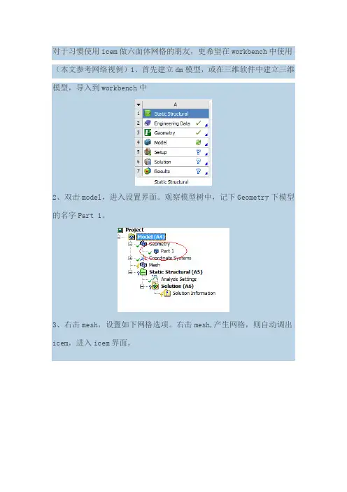
对于习惯使用icem做六面体网格的朋友,更希望在workbench中使用(本文参考网络视例)1、首先建立dm模型,或在三维软件中建立三维模型,导入到workbench中
2、双击model,进入设置界面。
观察模型树中,记下Geometry下模型的名字Part 1。
3、右击mesh,设置如下网格选项。
右击mesh,产生网格,则自动调出icem,进入icem界面。
4、进入icem中,系统自动分块,而这个分块是我们不想要的,因此删除块,重新分块,生产新块时,注意手动选择part名称,保证与2中名字一致。
(part 1,这里是part_1_1_1)
5、icem中划分网格,结果如下
6、产生结构网格,File-Mesh-From....,保存网格,点击yes
7、进行简单的设置,简单的做了个计算,如图所示:。
ansys icem cfd网格划分技术实例详解纪
ansys icem cfd网格划分技术实
例详解纪
ANSYS ICEM CFD网格划分技术实例详解纪:
1、首先,选择你要建立的几何图形,如某个物体的外形、内部结构等;
2、选择网格划分的方法,可以使用Tetrahedron、Hexahedron、Prism等划分方法;
3、设定网格划分的精度,即划分后各三角形面或者正方体面的边长,一般可以根据不同类型的流动情况来调整精度;
4、确定各个区域的网格密度,一般需要在边界层提高网格数量,以更好地模拟流体的运动情况;
5、检查网格的质量,消除网格中的闭合面,以保证网格的准确性;
6、计算流场,对网格进行求解,并作图显示。
ICEM CFD教程
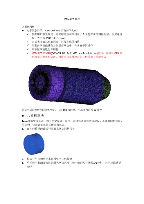
ICEM CFD教程四面体网格⏹对于复杂外形,ICEM CFD Tetra具有如下优点:✓根据用户事先规定一些关键的点和曲线基于8叉树算法的网格生成,生成速度快,大约为1500 cells/second✓无需表面的三角形划分,直接生成体网格✓四面体网格能够合并到混合网格中,并实施平滑操作✓单独区域的粗化和细化✓ICEM CFD的CAD(CATIA V4, UG, ProE, IGES, and ParaSolid, etc)接口,保留有CAD几何模型的参数化描述,网格可以在修改过的几何模型上重新生成这是生成的燃烧室四面体网格,共有660万网格,生成时间约为50分钟⏹八叉树算法Tetra网格生成是基于如下的空间划分算法:这种算法需要的区域保证必要的网格密度,但是为了快速计算尽量采用大的单元。
1.在几何模型的曲线和表面上规定网格尺寸2.构造一个初始单元来包围整个几何模型3.单元被不断细分来达到最大网格尺寸(每个维的尺寸按照1/2分割,对于三维就是1/8)4.均一化网格来消除悬挂网格现象5.构造出最初的最大尺寸单元网格来包围整个模型6.节点调整以匹配几何模型形状7.剔除材料外的单元8.进一步细分单元以满足规定的网格尺寸要求9.通过节点的合并、移动、交换和删除进行网格平滑,节点大小位于最大和最小网格尺寸之间⏹ 非结构化网格的一般步骤1. 输入几何或者网格所有几何实体,包括曲线、表面和点都放在part 中。
通过part 用户可以迅速打开/关掉所有实体,用不同颜色区分,分配网格,应用不同的边界条件。
几何被收录到通用几何文件.tin 中,.tin 文件可以被ANSYS ICEM CFD’s 所有模块1.1输入几何体Import Geometry✓ 第三方接口文件:ParaSolid 、STEP 、IGES 、DWG 、GEMS 、ACIS …✓ 直接接口:Catia 、Unigraphics 、Pro/E 、SolidWorks 、I-deas… 几何变化网格可以直接随之变化导入几何体之后,ICEM 自动生成B-spline 曲线和曲面,并在预先规定的点上设置顶点。
ANSYS ICEM CFD中文教程
ANSYS.ICEM-CFD中文教程ICEM CFD 工程Tutorials目录中每个工程是一个次级子目录。
每个工程的目录下有下列子目录:import, parts, domains, mesh, 和transfer。
他们分别代表:• import/: 要导入到ICEMCFD中的集合模型交换文件,比如igs,STL等;• parts/: CAD模型• domains/: 非结构六面体网格文件(hex.unstruct), 结构六面体网格分区文件(domain.n), 非结构四面体网格文件(cut_domain.1)• mesh/: 边界条件文件(family_boco, boco),结构网格的拓扑定义文件(family_topo, topo_mulcad_out), 和Tetin几何文件(tetin1).• transfer/: 求解器输入文件(star.elem), 用于Mom3d.的分析数据mesh目录中Tetin文件代表将要划分网格的几何体。
包含B-spline曲面定义和曲线信息,以及分组定义Replay 文件是六面体网格划分的分块的脚本鼠标和键盘操作第二章ICEM CFD Mesh Editor界面The Mesh Editor, 创建修改网格的集成环境,包含三个窗口• The ICEM CFD 主窗口• 显示窗口• The ICEM CFD 消息窗口主窗口主窗口中除了图形显示区域,外,还有6个radio按钮:File, Geometry, Meshing, Edit Mesh and Output.The File MenuThe File menu 包含• Open, Save, Save as, Close, Quit, Project dir, Tetin file,Domain file, B.C file, Import geo, Export geo, Options, Utilities,Scripting, Annotations, Import mesh, DDN part.The Geometry MenuThe Geometry menu 模型修补和编辑,边界条件的设置,调用ICEM CFD DDN。
ICEM_CFD基础入门教程操作界面中文
ICEM_CFD基础入门教程操作界面中文ICEM_CFD是一款常用的计算流体力学(CFD)前处理软件,它可以用来进行几何建模、网格生成以及网格质量改进等操作。
本教程将介绍ICEM_CFD软件的基础入门操作界面,并详细说明其主要功能和使用方法。
1.工作窗口:-图层窗口:用于管理不同的几何元素和网格单元。
可以将几何模型和网格分别分配到不同的图层中,便于管理和操作。
2.工具栏:-文件操作:包括新建、打开、保存和导出等文件操作。
-网格操作:包括网格划分、网格改进、网格质量检查和网格参数设置等操作。
-显示选项:可以选择显示几何模型、网格和图层等,方便用户对模型进行观察和分析。
-操作模式:设置不同的操作模式,如选择模式、移动模式、旋转模式和缩放模式等,方便用户进行几何模型和网格的操作和调整。
3.属性窗口:-几何模型属性:可以设置几何模型的名称、颜色和透明度等属性。
-网格生成属性:可以设置网格单元类型、边界条件和网格参数等属性。
-网格质量属性:可以设置网格质量检查和改进的参数和标准。
-显示属性:可以设置几何模型和网格的显示方式、颜色和透明度等属性。
4.建模流程:在ICEM_CFD中,进行建模和网格生成的一般流程如下:-导入CAD几何模型:可以通过导入现有的CAD几何模型文件,如STEP、IGES或者CATIA等文件格式,或者直接在ICEM_CFD中手动创建几何模型。
-网格划分:在几何模型的基础上进行网格划分,可以使用不同的网格划分算法和参数设置,生成合适的网格。
-网格改进:对生成的网格进行质量检查和改进,可以使用网格质量检查工具来查看和修复网格质量问题,并采用网格平滑和网格形变等操作来改进网格质量。
-边界条件设置:在网格上设置边界条件,包括流动边界条件、壁面边界条件和入出口边界条件等。
- 导出网格:将生成的网格导出为适用于CFD计算的文件格式,如ANSYS Fluent、OpenFOAM等格式。
通过上述步骤,可以完成几何建模和网格生成的基本操作和流程。
ICEMCFD基础教程A2-几何操作
只显示曲线
一个重要的初始步骤为创建缺失的曲线, 建立连通的几何并诊断几何 Geometry -> Repair -> Build Topology 这可以看作是geometry 标签栏最重要的按钮, 所以我们应关注每一个细节.
2023/9/3
ICEM CFD/AI*Environment 5.0
6
Building Topology 建立拓扑
创建复杂的模型是可以实现的, 我们只 对一些重要的功能作简略的概述 – 导入模型 – 建立拓扑结构 – 生成中面
采用ICECFD几何工具生成的带有反推 力装置的喷气发动机模型
2023/9/3
ICEM CFD/AI*Environment 5.0
2
几何操作
创建点
•从屏幕 •指定坐标 •平移 •中心点 •中间点 •端点 •交点 •沿曲线 •投影到曲线/曲面
ICEM CFD/AI*Environment 5.0
5
几何导入
使用 Geometry -> Import . . . CAD 文件 最初转换成 tetin (*.tin) 格式, 然后引入ICEMCFD/ AI*Environment
几何表现为一些为连接到一起的线和面, 即使是实体模型也将作为线和面导入.
在 Workbench 环境下, Design modeler 数据库可转换为 AI*Environment.
小平面数据格式: 将三角数据看作划分网格的几何 – Mesh Formats – STL – VRML
Pro/E 和UG 导入需要 Cad 库文件, 因此 CAD 软件 和注册必须能够使用时才能输入格式
– Catia V4 & V5
– UG
ICEM CFD划好网格导入ANSYS的成功方法
ICEM CFD 划好网格导入到ANSYS的成功案例第一步:导入几何文件Ug一般选择parasolid的x_t的格式,而proe导成step/iges 较好。
第二步:划分网格由于该部分不是导入的重点,就省略了,网格图如下。
第三步:打开solve option的工具条直接选择后,就会弹出如下对话框。
其中solver选择ansys求解器,edit option选择advanced这样就可以修改网格的材料,实常数,横截面,单元类型,但是这些都可以在ansys中修改除了单元类型。
单元类型的选择也直接关系到是否能导入成功以及导入后求解的精度。
所以这里主要讲一下单元类型的选择,至于其他参数在ansys 中可以修改。
单机,出现如下图。
选择单元类型的原则:按道理划分六面体后选择的单元类型要选择六面体单元,划分的网格是四面体网格时要选择四面体单元,六面体单元挺多,但是四面体单元有solid187但是行不通(现在还没找到原因)但是可以用solid45、65来代替,这样就会使多出来的节点消失了,(导入ansys观察节点数和单元数就可以发现),但影响不大。
第四步:选择完单元后单机apply出现下图提示你没有ansys.ansys.atr的工作目录,没关系,因为你刚创建本来就没有这个文件,这时单机创建attribute和parameter的文件,再单击还会弹出之前的单元选择对话框,这时要重新选择单元类型solid45。
完事单机accept出现下图;选择attribute的文件类型即可,表示可以有ansys.ansys.atr 的工作目录了。
最后单机apply就可成功导出。
第五步:ansys打开in文件。
上左图就是导入后的网格图。
接下来就是修改参数,由于是例子所以参数较简单,只是静态分析。
上图是icem导入后的单元属性,可以看出是一致的。
设置材料属性。
这些都完事后既可以施加约束和载荷了,由于导入的只有网格和单元,所以要通过component来实现载荷的施加。
- 1、下载文档前请自行甄别文档内容的完整性,平台不提供额外的编辑、内容补充、找答案等附加服务。
- 2、"仅部分预览"的文档,不可在线预览部分如存在完整性等问题,可反馈申请退款(可完整预览的文档不适用该条件!)。
- 3、如文档侵犯您的权益,请联系客服反馈,我们会尽快为您处理(人工客服工作时间:9:00-18:30)。
ANSYS.ICEM-CFD中文教程ICEM CFD 工程Tutorials目录中每个工程是一个次级子目录。
每个工程的目录下有下列子目录:import, parts, domains, mesh, 和transfer。
他们分不代表:•import/: 要导入到ICEMCFD中的集合模型交换文件,比如igs,STL 等;• parts/: CAD模型• domains/: 非结构六面体网格文件(hex.unstruct), 结构六面体网格分区文件(domain.n), 非结构四面体网格文件(cut_domain.1)•mesh/: 边界条件文件 (family_boco, boco),结构网格的拓扑定义文件(family_topo, topo_mulcad_out), 和Tetin几何文件(tetin1). •transfer/: 求解器输入文件(star.elem), 用于Mom3d.的分析数据mesh目录中Tetin文件代表将要划分网格的几何体。
包含B-spline曲面定义和曲线信息,以及分组定义Replay 文件是六面体网格划分的分块的脚本鼠标和键盘操作鼠标或键盘操作功能鼠标左键点击和拖动旋转模型鼠标中键点击和拖动平移模型鼠标右键点击和上下拖动缩放模型鼠标右键点击和左右拖动绕屏幕Z轴旋转模型第二章ICEM CFD Mesh Editor界面The Mesh Editor, 创建修改网格的集成环境,包含三个窗口• The ICEM CFD 主窗口•显示窗口• The ICEM CFD 消息窗口主窗口主窗口中除了图形显示区域,外,还有6个radio按钮:File, Geometry, Meshing, Edit Mesh and Output.The File MenuThe File menu 包含• Open, Save, Save as, Close, Quit, Project dir, Tetin file, Domain file, B.C file, Import geo, Export geo, Options,Utilities,Scripting, Annotations, Import mesh, DDN part.The Geometry MenuThe Geometry menu 模型修补和编辑,边界条件的设置,调用ICEM CFD DDN。
它包含• DDN tools, Bound conds, Repair, Utilities, Global setup.模型编辑模式,由一排彩色radiobuttons操纵• Surface, Curve, Point, Material, Density, Loop.它们又分不具有次级菜单• Create, Delete, Modify, Mesh params, Change family,Copy/move.The Meshing MenuThe meshing menu 包含ICEM CFD各种网格划分模块。
只有用户拥有楼阁模块的license,他才能够使用那个模块。
目前ICEMCFD提供下列模块:• Hexa, Tetra, Global, Prism, Quad, AutoHexa, Mulcad/Padamm, P-Cube按不同的按钮会调用不同的模块。
The Edit Mesh MenuThe Edit Mesh menu包含必要的网格编辑功能, 粗化、平滑合并等。
具体的操作有:• Copy/move, Smooth, Refine, Coarsen, Merge, Extrude, Diagnostics, Uncouple, Bandwidth, Change type, Changefamily, Utilities, Edit nodes, Edit elements, Edit edges, Edit Blocks, Edit subfaces, RepairThe Output MenuThe Output menu针对不同求解器进行边界条件的设置。
此外用户能够调用Mom3d 和 Visual3 进行网格自适应和可视化。
可使用的功能有:• Select solver, Bound conds, Solver params, Solver input, Run solver, Visual3, Mom3d, RAMM-ICENote: The ICEM CFD 后处理模块 Visual3, 网格优化模块Mom3d, 以及与RAMM-ICE的内燃机网格接口必须有另外的licenseThe Utilities Cluster这些功能都位于主窗口的右上角:• Help: connects the user to the ICEM CFD on-line help• Orient: 操纵显示坐标• View: 定制显示属性• Undo: 操作反悔• Redo: 撤销反悔• Print: 打印• Shell: 调用一个X-Term命令窗口显示窗口The display window, 处于屏幕右边, 同意操纵按照family, geometric entity, elementtype and user-defined subsets来显示.Important: Since some functions are performed only on the entitiesshown, the Display window is a very important feature to use when isolating the particular entities to be modified.FamiliesColor-coded and customizable, display by family, as defined in themesher interface, is available in this window.GeometryWhen this button is toggled on, the user has control over the display of geometric entities. The Opts button beside for each entity type allows control over the display characteristics. Note: Based on the domain file chosen, this toggle button will either be labeled “unstructured” or “structured,” or be absentaltogether if no domain file is specified.• Structured or Unstructured: Aside from display of the mesh based on element type, for even greater power, ICEM CFD allows the user to create custom subsets; the careful display of which allows a great deal of control in the mesh operations. •Display Subset: This toggle button allows you to define subset of your model based on a set of numerous attributes, includingelement type, screen selection, coordinate position, etc.第三章 ICEM CFD Tetra四面体网格划分器自动对CAD模型或者STL模型生成四面体网格,无需先生成表面网格这是Tetra生成的棱拄和四面体混合网格,包含55万四面体网格和12层33万棱拄网格介绍Tetra采纳8叉树算法来对体积进行四面体填充并生成表面网格。
用户必须事先规定一些关键的点和曲线。
Tetra具有强大的网格平滑算法,以及局部适应性加密和粗化算法。
关于复杂模型,ICEM CFD Tetra具有如下优点:•基于8叉树算法的网格生成•快速模型set-up•网格与表面拓扑独立•无需表面的三角形划分•能够直接从CAD模型和STL数据进行网格生成•对CAD surfaces and/or STL Representation定义网格尺寸•操纵体积内部的网格尺寸•四面体的节点和曲线与事先的规定匹配•采纳Natural size 单独的决定几何特征上的四面体网格尺寸•体积网格和表面网格的平滑、节点合并和边交换•四面体网格能够合并到混合网格中,并实施平滑操作•单独区域的粗化• Enforcement of mesh periodicity, both rotational and translational•表面网格编辑和诊断工具•局部细化和粗化•为多种材料提供一个统一的网格•快速算法: 1500 cells/secondICEM CFD Tetra的输入ICEM CFD Tetra的输入方法有:• Sets of B-Spline curves and trimmed B-Spline surfaces with prescribed points• Triangular surface meshes as geometry definitionICEM CFD Tetra中的智能几何ICEM CFD的CAD接口,保留有CAD几何模型的参数化描述,网格能够在修改过的几何模型上重新生成。
在CAD中选中被导入的模型带有附加的信息,它们与主几何模型一起存储,几何模型的参数改变后,用户要重新生成网格只需简单的File > Save,就能够立即进行非结构四面体网格重新计算。
八叉树算法Tetra网格生成是基于如下的空间划分算法:这种算法需要的区域保证必要的网格密度,然而为了快速计算尽量采纳大的单元。
1.在几何模型的曲线和表面上规定网格尺寸2.构造一个初始单元来包围整个几何模型3.单元被不断细分来达到最大网格尺寸(每个维的尺寸按照1/2分割,关于三维确实是1/8)4.均一化网格来消除悬挂网格现象5.构造出最初的最大尺寸单元网格来包围整个模型6.节点调整以匹配几何模型形状7.剔除材料外的单元8.进一步细分单元以满足规定的网格尺寸要求9.通过节点的合并、移动、交换和删除进行网格平滑Family设置, Material Points, 预先规定Points在ICEMCFD中能够对几何模型中的各种几何元素进行分组,形成不通的families。