RT8016GQW中文资料
TCLMS801机芯电路原理与故障检修实例资料

TCLMS801机芯电路原理与故障检修实例资料TCL MS801机芯液晶彩电主要电路原理、调试与检修实例杨德印TCL MS801机芯的系列机型属于Android 智能数字电视,基本功能包括模拟ATV、数字DTV、互联⽹、全信源3D 和Android 4.0 UI。
主要的型号有L46V7500A-3D、L55V7500A-3D、L65V7500A-3D等。
各个电路板的连接如图1所⽰。
图1⼀、电源电路该机的电源电路由主电源电路(24V电源)、待机电源电路(3V3SB电源)、12V电源、5V电源、3.3V 电源、2.5V电源等构成,如图2所⽰。
图21.24V、3V3SB电源电路24V、3V3SB电源设置在电源板上,其中3V3SB电源是不受控电源,通电后就会进⼊⼯作状态,为微控制系统提供3.3V⼯作电源。
24V电源是受控电源,开机时来⾃微控制器电路的待机/开机信号POWER_ON 为⾼电平时,24V电源才能⼯作并输出24V电压;待机时POWER_ON为低电平,24V电源⽆电压输出。
2.12V、5V电源电路12V、5V电压由24V电压经DC-DC型功率变换器转换⽽来,如图3所⽰。
12V、5V电源电路的构成和⼯作原理相同,仅元器件符号不同,下⾯以12V电源电路为例进⾏介绍。
图3(1)电压变换24V电压经L008、L009和C029滤波后,⼀路为5V电源供电;另⼀路不仅加到模块Q003的⑤、⑥脚,为内部的下端开关管(场效应管)漏极供电,⽽且加到电源控制芯⽚U004(RT8110B)的7脚,为它供电。
U004内的控制电路得电⼯作,产⽣⼀组对称但极性相反的激励脉冲信号从②④脚输出。
当②脚输出的激励信号为低电平、④脚输出的激励信号为⾼电平时,使Q003内的上端开关管截⽌,⽽使下端的开关管导通,该开关管导通后,24V电压经它的D/S极和电感L004对C068、C069、C074充电,不仅在它们两端建⽴电压,⽽且在L004两端产⽣左正、右负的电动势;当4脚输出的激励信号为低电平②脚输出的激励信号为⾼电平时,使Q003内的下端开关管截⽌,⽽使上端的开关管导通,该开关管导通后,L004 通过⾃感产⽣右正、左负的电动势,该电动势通过C068、C069、C074到地,再通过Q003内的上开关管到L004左端构成放电回路,继续为C068、C069、C074补充能量,从⽽提⾼了该电源的⼯作效率。
QSAN XN8016R 硬件使用手册说明书
XN8016R版本 1.2 ( December 2018 )本版本适用于QSAN XCubeNAS XN8016R NAS储存设备。
QSAN在本出版品中的信息由公布日起发生效力。
如有更改,恕不另行通知。
商标QSAN、QSAN 标志、XCubeNAS、 均为 QSAN Technology, Inc. 的注册商标。
Intel、 Xeon、Pentium、Core、Celeron、Intel Inside 等标志均为 Intel 公司在美国和其他国家/地区的注册商标。
本手册中用来表示其他商标、名称、产品所使用的注册商标和名称,均为其所属公司或所有人的财产。
注意本手册中包含其信息已通过审查确认,但仍可能产生印刷错误或技术描述不准确。
若有变更将会定期更改,并被纳入新版本的出版文件中。
QSAN可能会持续进行改进或调整产品本身及内容。
所有功能和产品规格如有更改,恕不另行通知或履行任何义务。
本文中的所有声明、信息和建议均不构成任何明示或暗示的保证。
本文包含的任何性能数据都在控制的环境中决定。
因此,在其他操作环境中获得的结果可能会略有不同。
相关测量都在开发中的系统上进行,并不能保证在一般的系统上都能呈现相同的结果。
此外,一些测量可能是透过推估的,实际结果可能会有所不同。
用户应对其特定环境进行个别验证。
本文信息包含日常中会使用的数据和报告实例。
为了尽可能完整地说明,这些例子可能包括个人、公司、品牌和产品名称。
所有名称皆为虚构,若与实际企业名称或地址有任何相似性纯属巧合。
法规声明CE StatementThis device has been shown to be in compliance with and was tested in accordance with the measurement procedures specified in the Standards and Specifications listed below.Technical Standard: EMC DIRECTIVE 2014/30/EU Class A(EN55032 / EN55024)FCC StatementThis device complies with Part 15 of the FCC Rules. The Operation is subject to the following two conditions:1. This device may not cause harmful interference.2. This device must accept any interference received, including interference that maycause undesired operation.Contents iiiThis equipment has been tested and found to comply with the limits for a Class Adigital device, pursuant to Part 15 of the FCC Rules. These limits are designed toprovide reasonable protection against harmful interference when the equipment isoperated in a commercial environment. This equipment generates, uses, and canradiate radio frequency energy and, if not installed and uses in accordance with theinstruction manual, may cause harmful interference to radio communications.Operation of this equipment in a residential area is likely to cause harmful interferencein which case the user will be required to correct the interference at his own expense.Notice: The changes or modifications not expressly approved by the party responsiblefor compliance could void the user’s authority to operate the equivalent.BSMI Statement警告:这是甲类的信息产品。
最新BL1616(LED驱动芯片)中文资料
参数
逻辑电源电压
逻辑输入电压
LED SEG 驱动输出电流
LED GRID 驱动输出电流
工作温度
储存温度
电气特性(Ta = 25℃)
参数
符号
逻辑电源电压
VDD
高电平输入电压 VIH
低电平输入电压 VIL
静态电流
IDD
SDA、SCL 上拉电阻 RSDA、RSCL
SEG 驱动电流
ISEG
GRID 驱动电流
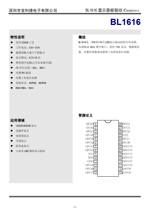
BL1616 显示面板驱动 ICISOS2013V1.0
BL1616
概述
BL1616是一种8 段×16 位 LED显示驱动控制专用电路, 内部集成 MCU 数字接口、采用 I^2C 协议、数据锁存 器、内置时钟振荡电路和上电掉电复位电路。
应用领域
VCD/DVD/DVB 显示 电磁炉显示 电饭煲显示 空调显示 机顶盒显示 小家电 LED 数码显示驱动
逻辑电源
25
GRID0—GRID15
输出(位)
4-8,12-22
GND
逻辑地
11
注:SEG 引脚连接 LED 阳极,GRID 引脚连接 LED 阴极。
说明 I2C 总线串行接口的时钟输入 I2C 总线串行接口的数据输入 段输出 5V±10% 位输出 系统地
-2-
电气参数
极限参数(Ta = 25℃)
显示开关设定: 0:显示关 1:显示开
SCL
SDA
Command1
start
ack
Data1 ack
Command1:设置地址 Data1~n : 传输显示数据(最多 16byets) Command2:控制显示 固定地址模式
模块大全
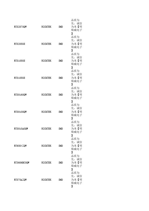
RT8207GQW RICHTEK SMD 先,诚信为本【明烽威电子】RT8205GS RICHTEK SMD 品质为先,诚信为本【明烽威电子】RT8105GS RICHTEK SMD 品质为先,诚信为本【明烽威电子】RT8105GS RICHTEK SMD 品质为先,诚信为本【明烽威电子】RT8016GQW RICHTEK SMD 品质为先,诚信为本【明烽威电子】RT8010GQW RICHTEK SMD 品质为先,诚信为本【明烽威电子】RT8010AGQW RICHTEK SMD 品质为先,诚信为本【明烽威电子】RT6504ZQW RICHTEK SMD 品质为先,诚信为本【明烽威电子】RT3606BCGQW RICHTEK SMD 品质为先,诚信为本【明烽威电子】RT870AZQW RICHTEK SMD 品质为先,诚信为本【明烽威电子】R7711AGE RICHTEK SMD 先,诚信为本【明烽威电子】TSM104WAIDT ST SMD STM8L152R8T6ST SMD STK3321-28A SENSORT SMD SKY77916-31SKYWORK SMD SKY77916-21SKYWORK SMD SKY77643-31SKYWORK SMDNUC029LAN Nuvoton TechnologyCorpSMDNQ2102D2EV NXP SMD NQ2102D2EV/C101Y NXP SMD CX93510-12ZP1CONEXAN SMD BQ24735RGRR TI SMD 明烽威电子明烽威电子VVZ110-12IO7IXYS IGBT VVZ24-16IO1IXYS IGBT VVZ24-12IO1IXYS IGBT SKM400GB07E3SEMIKRON IGBT SKKT323/16E SEMIKRON IGBT SKKT323/12SEMIKRON IGBT SKHI01TR SKHI01TR IGBT PM800HSA060MITSUBISHI IGBT MWI150-12T8T IXYS IGBT FRS300BA50SANREX IGBT FP25R12W2T4_B11Infineon IGBT FP25R12W2T4Infineon IGBT CM600DX-24T MITSUBISHI IGBT CM600DX-24S1MITSUBISHI IGBT 明烽威电子MITSUBISHI IGBT CM600DXL-24S MITSUBISHI IGBT CM600DX-24T MITSUBISHI IGBT CM600DX-13T MITSUBISHI IGBT CM600DXLE-24A MITSUBISHI IGBT CM450DX-24T MITSUBISHI IGBT CM450DX-24T#300G MITSUBISHI IGBT2MBI600VN-120-50FUJIELECTRICIGBT2MBI150U4B-120FUJIELECTRICIGBT2MBI150U4B-120-50-C FUJIELECTRICIGBT2MBI150U4B-120-50FUJIELECTRICIGBT2MBI75L-120FUJIELECTRICIGBT2MBI75L-120X3FUJIELECTRICIGBT2MBI150U4A-120-50FUJIELECTRICIGBT2MBI150U4A-120-50-C FUJIELECTRICIGBTVVZ110-14IO7IXYS IGBT VVZ110-12io7IXYS IGBT VVZ24-16I01IXYS IGBT VVZ24-16i01IXYS IGBT 明烽威电子IXYS IGBT VVZ24-12I01IXYS IGBT VUO121-16NO1IXYS IGBT TDB6HK124N16RR Infineon IGBT SKYPER32R SEMIKRON IGBT SKM300MLI066TAT SEMIKRON IGBT SKM40GAH123D SEMIKRON IGBT SKKH106/16E SEMIKRON IGBT SKKH72/16E SEMIKRON IGBT SKKH57/16E SEMIKRON IGBT SKIIP39AHB16V1SEMIKRON IGBT SKIIP26NAB066V1SEMIKRON IGBT SKIIP23NAB126V10SEMIKRON IGBT SKIIP22NAB12T18SEMIKRON IGBT SKIIP13NAB065V1SEMIKRON IGBT SKHI24SEMIKRON IGBT SKHI24R SEMIKRON IGBT SKHI22BH4R SEMIKRON IGBT SKDH146/16-L105SEMIKRON IGBT SK75GAL12T4SEMIKRON IGBT SEMiX603GB12E4p SEMIKRON IGBT SEMiX603GB12E4p SEMIKRON IGBT PSD82/16POWERSE IGBT PM800HSA060MITSUBISHI IGBT PM300DVA120MITSUBISHI IGBT PM300DSA120MITSUBISHI IGBT PK200FG160SANREX IGBT PD100KN16NIEC IGBT MMG100J120UZ MACMIC IGBT MDD255-20N1IXYS IGBT MCC225-16IO1IXYS IGBT K220A4002TYCO IGBT K220A4003TYCO IGBT K220A4001TYCO IGBT GD50HFL120C1S STARROW IGBTFS150R06KE3Infineon TechnologiesIGBT明烽威电子Infineon TechnologiesIGBTFS100R12KS4TechnologiesIGBTFS15R12YT3Infineon TechnologiesIGBTFF100R12MT4Infineon TechnologiesIGBTFD200R12KE3Infineon TechnologiesIGBTF4-75R12MS4Infineon TechnologiesIGBT明烽威电子Infineon TechnologiesIGBTF3L150R07W2E3Infineon TechnologiesIGBTF3L150R07W2E3_B11Infineon TechnologiesIGBTDDB6U84N16RR Infineon TechnologiesIGBTCM500HA-34A MITSUBISHI IGBT CM500HA-34A MITSUBISHI IGBT CM300DY-12H MITSUBISHI IGBT CM200DY-24A MITSUBISHI IGBT CM200DY-12H MITSUBISHI IGBTBSM150GB120DN2Infineon TechnologiesIGBTBSM100GD120DN2Infineon TechnologiesIGBTAPT60GF120JRD APT IGBTA50L-0001-0326FUJIELECTRICIGBT6MBP30RTB060-50FUJIELECTRICIGBT2SD315AI CONCEPT IGBT2MBI100U4H-170FUJIELECTRICIGBT2MBI75S-120FUJIELECTRICIGBT2MBI75N-120FUJIELECTRICIGBT2A200HB17C2L TechnologiesIGBT1MBI300N-120FUJIELECTRICIGBT2A200HB17C2L Infineon TechnologiesIGBTSKM300GB12T4SEMIKRON IGBT SKM300GA123D SEMIKRON IGBT SKM150GB128D SEMIKRON IGBT SKM150GB12T4G SEMIKRON IGBT SKM100GB176D SEMIKRON IGBT SKM100GB123D SEMIKRON IGBT SKM75GB176D明烽威电子IGBT SKM75GB123D明烽威电子IGBT SKKE600F12SEMIKRON IGBT SKKE330F17SEMIKRON IGBT SKKD162/16明烽威电子IGBT SKKD106SEMIKRON IGBT SKKD106/16E明烽威电子IGBT SKKD81SEMIKRON IGBT SKKD81/14SEMIKRON IGBT 明烽威电子SEMIKRON IGBT SKKD81/04SEMIKRON IGBT SKKD81/18明烽威电子IGBT SKKD81/14SEMIKRON IGBT SKET740明烽威电子IGBT SKET740/22GH4SEMIKRON IGBT SKET740/18E明烽威电子IGBT SKET740/12SEMIKRON IGBT SKET740/18GH4SEMIKRON IGBT SKET740/22GH4SEMIKRON IGBT SKD146/16-L140T4SEMIKRON IGBT SK75GAR12T4明烽威电子IGBT SK60GAL125明烽威电子IGBT SK35GD126ET SEMIKRON IGBT PSD82/16POWERSE IGBT PM200DVA120明烽威电子IGBTPM150CVA120MITSUBISHI 明烽威电子PM50RLB120MITSUBISHI IGBT 明烽威电子MITSUBISHI IGBT PM50B6LA060明烽威电子IGBT PM50B5LA060MITSUBISHI IGBT PM30CTJ060MITSUBISHI IGBT MWI100-12T8T IXYS IGBT MWI100-12E8IXYS IGBT MMF200ZB040DK1C MACMIC IGBT MMF200ZB040DK1C MACMIC IGBT MIG50Q7CSB1X MITSUBISHI IGBTMDST100-16GUERTE IGBT MDC160-16IXYS IGBT GD400HFL120C2S STARPOW IGBT GD300HFL120C2S STARPOW IGBTFZ1200R33HE3Infineon TechnologiesIGBTFT150R12KE3G Infineon TechnologiesIGBTFT150R12KE3G Infineon TechnologiesIGBTFS300R12KE3Infineon TechnologiesIGBTFS200R12PT4Infineon TechnologiesIGBTFP75R12KT4Infineon TechnologiesIGBTFP50R12KT4Infineon TechnologiesIGBTFP50R12KT3Infineon TechnologiesIGBTFF1200R17KE3Infineon TechnologiesIGBTFF450R06ME3Infineon TechnologiesIGBTFF400R33KF2C Infineon TechnologiesIGBTFF150R12RT4明烽威电子IGBTF4-75R12MS4Infineon TechnologiesIGBTDP450B1700T102821DANFOSS IGBT DM2G100SH6A DAWIN IGBT DIM400GDM33-F076DYNEX IGBT DIM400GDM33-F000DYNEX IGBT DH2F100N4S DAWIN IGBTDDB6U104N16RR Infineon TechnologiesIGBTCM600DU-24F MITSUBISHI IGBT CM450DX-24S1MITSUBISHI IGBTCM400HU-24F MITSUBISHI IGBT CM400DU-24F MITSUBISHI IGBT CM400DU-12F MITSUBISHI IGBT CM300DU-24NFH MITSUBISHI IGBT CM200DY-12NF MITSUBISHI IGBT CM150RL-24NF MITSUBISHI IGBT CM150DC1-24NFM MITSUBISHI IGBT CM100TX-24S MITSUBISHI IGBT BSM150GT120DN2明烽威电子IGBTBSM50GD170DL Infineon TechnologiesIGBTBSM10GP120Infineon TechnologiesIGBT7MBR15SA120-50FUJIELECTRICIGBT6MBI50S-120FUJIELECTRICIGBT4MBI400VF-120R-50FUJIELECTRICIGBT2SD106AI-17CONCEPT IGBT2MBI450VN-120-50FUJIELECTRICIGBT2MBI200U2A-060-50FUJIELECTRICIGBT1MBI400NA-120-02FUJIELECTRICIGBT1MBI400NA-120FUJIELECTRICIGBT1MBI300SA-120B-52FUJIELECTRICIGBT1MBI300N-120FUJIELECTRICIGBT明烽威电子明烽威电子明烽威电子明烽威电子明烽威电子明烽威电子SKKH330/16E明烽威电子VUO98-16NO7IXYSVUO98-12N07IXYSVUO98-08NO7IXYSVUO98-18NO7IXYSFF200R17KE3Infineon Technologie s2A75HB12C1U Infineon Technologie sFP40R12KT3G Infineon Technologie sFP40R12KT3TechnologiesSKIIP39AHB16V1SEMIKRON CM300DY-12NF MITSUBISHI CM300DY-24H MITSUBISHI CM300DY-24A明烽威电子FS450R12KE3Infineon Technologie sFS450R17KE3Infineon Technologie sP089A2009明烽威电子P089A2004TYCOP089A2001TYCOP080A2006TYCOFS450R12KE4Infineon Technologie sFS450R12KE3Infineon Technologie sSKM145GB128D明烽威电子明烽威电子SEMIKRON SKM145GB123D SEMIKRON SKKH460/20E H4SEMIKRON SKKH460/22EH4明烽威电子SKKH460/16SEMIKRON SKKH460/12E SEMIKRON 2SC0435T2A0CONCEPT2SC0435T2A0-17CONCEPTFF200R12KT4Infineon Technologie sSKKT162/16E明烽威电子SKKT162/12E SEMIKRONTD142N16KOF Infineon Technologie sSKIIP03NAC126V1SEMIKRON SKIIP03NAC12T4V1明烽威电子SKIIP03NAC066V3SEMIKRON FB15R06KL4EUPECFB15R06KL4-B1EUPECFB15R06KL4_B1EUPECFZ1500R33HE3Infineon Technologie sFZ1500R33HL3Technologies2MBI1400VXB-170-54FUJI ELECTRIC2MBI1400VXB-170P-5明烽威电子2MBi1400VXA-170E-50FUJI ELECTRIC2MBI1400VXB-120P-50FUJI ELECTRIC2MBI1400VXA-170-50FUJI ELECTRIC2MBI1400VXB-120P-54FUJI ELECTRICPM50RLB120明烽威电子PM50RLB060MITSUBISHI MG200J2YS50TOSHIBA CM150G6X-24S1MITSUBISHIBSM150GB170DN2Infineon Technologie sBSM150GB170DLC Infineon Technologie sBSM150GB120DN2Infineon Technologie sBSM150GB60DLC Infineon Technologie sBSM150GB120DN2Infineon Technologie s2A200HB17C2L Infineon Technologie sFD200R12KE3Infineon Technologie sMCC255-16IO1IXYS2MBI650VXA-170E-50FUJI ELECTRICF3L100R07W2E3 B11Infineon Technologie sF3L100R07W2E3Infineon Technologie sDDB6U84N16RR EUPEC DDB6U84N16RR EUPEC2MBI300VN-120-5FUJI ELECTRICVUO121-16NO1IXYSCM450DX-24MITSUBISHI CM450DX-24T MITSUBISHIDD260N16K Infineon Technologie sSKKD162SEMIKRON SKKD162/16SEMIKRON SKKD162/12SEMIKRON GD35PJT120L3S STARPOWFF400R33KF2C Infineon Technologie sRM1500HE-66F MITSUBISHI 1SD536F2Concept1SD536F2-5SNA1500E330300Concept1SD536F2-5SNA2400E17010Concept1SD536F2-FX800R33KF2Concept1SD536F2-MIO2400-17E10Concept HAT1500-S LEMIKCM30F60GA LS2MBI1400VXB-120P-50FUJI ELECTRIC2MBI1400VXB-170P-54FUJI ELECTRIC2MBI1400VXB-170P-54FUJI ELECTRICBG200B12UX2S-I BYD BG200B12UY2-I BYDBSM150GB60DLC Infineon Technologie sBSM150GB60DLC。
EG8026芯片数据手册说明书

版本变更记录版本号日期描述V1.0 2022年01月20日EG8026数据手册初稿。
目录目录 (3)1.特点 (5)2.描述 (6)3.应用领域 (6)4.引脚 (7)4.1QFN70封装引脚定义 (7)4.2LQFP80封装引脚定义 (8)4.3引脚描述 (9)5.结构框图 (12)6.典型应用电路 (13)6.1EG8026 QFN70封装应用原理图 (13)6.2EG8026 LQFP80封装应用原理图 (14)6.348V/2KW双向逆变器主板应用图 (15)6.4EG1615 DC/DC控制板原理图 (16)7.电气特性 (17)7.1极限参数 (17)7.2典型参数 (18)8.应用设计 (20)8.1双向逆变器的主拓扑结构 (20)8.2EG8026实现的传统型Boost无桥PFC结构 (21)8.3EG8026实现的DC/AC Inverter结构 (22)8.4PFC和DC/AC Inverter、UPS功能切换 (23)8.5PWM调制方式 (23)8.6输出电压反馈 (24)8.7输出电流反馈 (26)8.8温度反馈 (27)8.9直流母线电压反馈和硬件过压保护 (27)8.10死区时间 (28)8.11H桥的左、右桥臂互换控制 (29)9.保护功能 (30)9.1输出过载保护 (30)9.2输出过流保护 (30)9.3直流母线电压过压保护 (30)9.4PCB过温保护 (30)9.5功率管过温保护 (30)9.6短路保护 (30)9.7MOS管峰值电流保护 (31)10.测试模式 (32)11.通讯功能(UART) (33)11.1串口描述 (33)11.2APP功能 (33)屹晶微电子有限公司11.2.1APP消息发送 (33)11.2.2APP消息接收 (34)11.3CFG功能 (36)11.3.1CFG请求消息 (36)11.3.2CFG应答消息 (36)11.3.30x10服务-会话切换 (37)11.3.40x22服务-读DID (38)11.3.50x2E服务-写DID (38)11.3.60x21 服务-读CFG (39)11.3.70x2D 服务-写CFG (39)11.3.80x2F服务-IO控制 (40)12.封装尺寸 (41)12.1LQFP80 (41)12.2QFN70 (42)屹晶微电子有限公司EG8026芯片数据手册V1.01. 特点集成了DC/AC逆变器和PFC升压两大功能支持UPS功能作逆变器DC/AC时的功能:⏹采用电流模式、中心对齐PWM调制方式,能带感性和容性负载⏹SPWM载波频率20KHz,适合大功率MOS管和IGBT管的应用⏹集成了两路600V半桥高压MOS管驱动器,驱动能力为±2A⏹集成四路独立的MOS管峰值电流保护电路及内置四路200mV基准源的比较器供用户设定保护值⏹集成了四路高速运放及一路高速比较器,两路运放用于交流电流放大器,一路运放用于交流输出电压反馈,一路运放用于短路保护和一路比较器用于限流保护⏹输出电压和输出电流是每个PWM周期实时处理,能实现精确跟踪⏹引脚可配置功能:●H桥左、右桥臂互换控制●4种死区时间可选配置: 300nS、500nS、1uS、1.5uS●2种固定正弦波频率可选配置:50Hz、60Hz●软启动开启和关闭⏹逆变器保护功能:●直流母线电压过压保护●交流输出欠压保护●输出过载保护●输出过流保护●PCB过温保护和IGBT过温保护●输出短路保护⏹串口通讯可设置参数:●50Hz纯正弦波固定频率●60Hz纯正弦波固定频率●交流输出电压●温度保护值●额定功率保护值●额定电流保护值●故障复位⏹串口通讯可读参数:●交流输出电压●交流输出频率●交流输出功率●交流输出电流●直流母线电压●故障代码作PFC升压时的功能:⏹采用传统型Boost无桥PFC结构,平均电流控制算法⏹SPWM载波频率20KHz,适合大功率MOS管和IGBT管的应用⏹升压输出电压由恒功率大小进行自动调节,正常电压为400V,可调电压范围为330V到450V⏹外部可设的硬件输出过压保护⏹交流输入电压欠压保护⏹输出过载和过流保护⏹支持UART串口通讯,实现跟前级DC/DC EG1615芯片进行通讯,读取充电电压和电流等信息⏹PF值可达0.98以上2. 描述EG8026芯片是一款专用于双向逆变器(同一套电路可作逆变器功能,又可作电池充电器功能)中的DC/AC逆变和PFC升压的控制芯片,集成了两路600V半桥高压MOS驱动器,驱动器的输出电流能力为+/-2A,内置四路独立的逐周PWM关断保护,可有效防止在极端情况下过高的峰值电流而损坏MOS的情况,另外提供了两路SD,分别为SD1,和SD2,SD1是驱动器1 HO1和LO1的逐周关断引脚,SD2是驱动器2 HO2和LO2的逐周关断引脚,结合外部比较器和SD功能可实现过流或短路保护等功能。
S-80856中文资料
Block Diagram
(1) Nch open-drain active low output (2) CMOS active low output
VDD +
−
VDD OUT +
−
*
OUT
* *
VREF VSS VSS
VREF
*Parasitic diode Figure 2
Selection Guide
Features
Applications
1.3 µA typ. (VDD=1.5 V)
Ultra-low current consumption
Products with detection voltage of 1.4 V or less electronic 0.8µA typ. (VDD=3.5 V) Products with detection voltage of 1.5‚uor more
s80856中文资料sg3525中文资料cd4051中文资料s8550pdf中文资料lm324中文资料12864中文资料bpmn20中文资料lm358中文资料l298n中文资料7805中文资料op07中文资料
元器件交易网
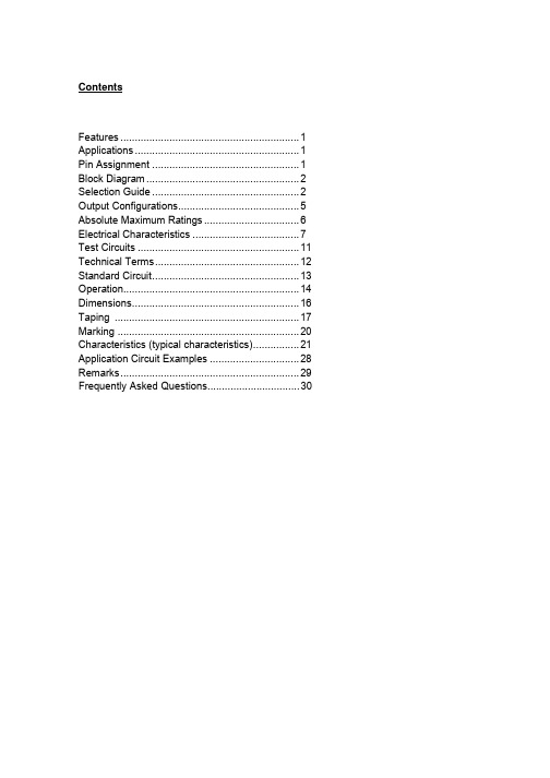
Contents
Features .............................................................. 1 Applications ......................................................... 1 Pin Assignment ................................................... 1 Block Diagram ..................................................... 2 Selection Guide ................................................... 2 Output Configurations.......................................... 5 Absolute Maximum Ratings ................................. 6 Electrical Characteristics ..................................... 7 Test Circuits ........................................................ 11 Technical Terms.................................................. 12 Standard Circuit................................................... 13 Operation............................................................. 14 Dimensions.......................................................... 16 Taping ................................................................ 17 Marking ............................................................... 20 Characteristics (typical characteristics)................ 21 Application Circuit Examples ............................... 28 Remarks.............................................................. 29 Frequently Asked Questions................................ 30
新普特 i16 温度传感器控制器说明书
I16D53IS1633IS1600I16D33-DCU Universal Inputs U H igh Accuracy: 0.5°C (±0.9°F), 0.03% Reading U Totally Programmable Color Displays (Visual Alarms)U User-Friendly,Simple to Configure U Free SoftwareU Full Autotune PID Control U Embedded Ethernet Connectivity Optional U RS232 and RS485 Serial Communications Optional U Built-In Excitation U 2 Control or Alarm Outputs Optional: DC Pulse, Solid State Relays, Mechanical Relays, Analog Voltage and CurrentU Output 3: Isolated Analog Voltage and Current OptionalU NEMA 4 (IP65) Front Bezel U Temperature Stability ±0.04°C/°C RTD and±0.05°C/°C Thermocouple @ 25°C (77°F)U Front Removable and Plug ConnectorsU AC or DC Powered Units U Ratiometric Mode for Strain Gages U Programmable Digital FilterThe NEWPORT ® i16 is the popular 1⁄16 DIN size (48 mm 2) controller. It is available with a single (model i16) or dual display (model i16D) that displays a setpoint along with the process value. The i16 display can be programmed to change color between GREEN, AMBER , and RED at any setpoint or alarm point. The i16 is the first 1⁄16 DIN controller with the option of both RS232 and RS485 in 1 instrument with both MODBUS ® serial protocoland the straightforward Newport ® ASCII protocol. And of course the i16 is the first 1⁄16 DIN controller that can connect directly to an Ethernet network and features an embedded Web server. Newport ® provides free configuration and data acquisition software downloaded off of the Web.The i16 enclosure has aNEMA 4 (IP65) rated front bezel. The electronics are removable from the front panel.i16D33 shown largerthan actual size.i1633 shown larger than actual size.1⁄16 DIN Temperature, Process andStrain PID Controllersi16 SeriesAccess Vital information Anytime,Anywhere, on the Internet!1⁄16 DIN controller withembedded Web server, dual control outputs, dual display.Ordering Examples: i1633, temperature/process controller,output 1 relay, output 2 relay single display, 90 to 240 Vac power.iS1643, strain/process controller, output 1 DC pulse, output 2relay, single display, 90 to 240 Vac power.*1 Ethernet options are available for the i16D and iS16D controllers only.*2 “-DC”, “-C24”, and “-C4EIT ” not available with excitation.*3 Analog output (option 5) is not available with “-AL ” units or i16A models.*4 20 to 36 Vdc for i16D , i16D-C4EIT , i16D-EIT and i16A *5 “-SM ” option not available on iS16 or i16A models.*6 Ethernet options are not available for i16A models.*7 For i16Axx-AL: One alarm and one analog retransmission.Universal Temperature and Process Input ("i" Models)Accuracy: ±0.5°C temp; 0.03% rdg Resolution: 1°/0.1°; 10 μV process Temperature Stability: RTD: 0.04°C/°CTC @ 25°C (77°F): 0.05°C/°C Cold Junction Compensation Process: 50 ppm/°C NMRR: 60 dB CMRR: 120 dBA/D Conversion: Dual slope Reading Rate: 3 samples/s Digital Filter: Programmable Display: 4-digit 9-segment LED 10.2 mm (0.40"); i32, i16, i16D, i8DV 21 mm (0.83"); i8 10.2 mm (0.40") and 21 mm (0.83"); i8DH RED , GREEN , and AMBER programmable colors for process variable, setpoint and temperature unitsInput Types: Thermocouple, RTD, analog voltage, analog currentThermocouple Lead Resistance: 100 Ω maxThermocouple Types (ITS 90): J, K, T, E, R, S, B, C, N, L (J DIN)RTD Input (ITS 68): 100/500/1000 Ω Pt sensor, 2-, 3- or 4-wire; 0.00385 or 0.00392 curveVoltage Input: 0 to 100 mV, 0 to 1V, 0 to 10 VdcInput Impedance: 10 M Ω for 100 mV 1 M Ω for 1 or 10 VdcCurrent Input: 0 to 20 mA (5 Ω load)Configuration: Single-ended Polarity: UnipolarStep Response: 0.7 sec for 99.9%Decimal Selection: Temperature: None, 0.1 Process: None, 0.1, 0.01 or 0.001Setpoint Adjustment: -1999 to 9999 counts Span Adjustment: 0.001 to 9999 countsOffset Adjustment: -1999 to 9999Excitation (Not Included withCommunication): 24 Vdc @ 25 mA (not available for low-power option)Universal Strain and Process Input ("iS" Models)Accuracy: 0.03% reading Resolution: 10/1μVTemperature Stability: 50 ppm/°C NMRR: 60 dB CMRR: 120 dBA/D Conversion: Dual slope Reading Rate: 3 samples/s Digital Filter: ProgrammableInput Types: Analog voltage and current Voltage Input: 0 to 100 mVdc, -100 mVdc to 1 Vdc, 0 to 10 VdcInput Impedance: 10 M Ω for 100 mV; 1 M Ω for 1V or 10 VdcCurrent Input: 0 to 20 mA (5 Ω load)Linearization Points: Up to 10Configuration: Single-ended Polarity: UnipolarStep Response: 0.7 sec for 99.9%Decimal Selection: None, 0.1, 0.01 or 0.001Setpoint Adjustment: -1999 to 9999 countsSpan Adjustment: 0.001 to 9999 counts Offset Adjustment: -1999 to 9999Excitation (Optional In Place Of Communication): 5 Vdc @ 40 mA; 10 Vdc @ 60 mAControlAction: Reverse (heat) or direct (cool)Modes: Time and amplitude proportional control; selectable manual or auto PID, proportional, proportional with integral, proportional with derivative and anti-reset Windup, and on/off Rate: 0 to 399.9 s Reset: 0 to 3999 sCycle Time: 1 to 199 s; set to 0 for on/off Gain: 0.5 to 100% of span; setpoints 1 or 2Damping: 0000 to 0008Soak: 00.00 to 99.59 (HH:MM), or OFF Ramp to Setpoint:00.00 to 99.59 (HH:MM), or OFF Auto Tune: Operator initiated from front panelControl Output 1 and 2Relay: 250 Vac or 30 Vdc @ 3 A (resistive load); configurable for on/off, PID and ramp and soakOutput 1: SPDT, can be configured as alarm 1 outputOutput 2: SPDT, can be configured as alarm 2 outputSSR: ******************.5A (resistive load); continuousDC Pulse: Non-isolated; 10 Vdc @ 20 mA Analog Output (Output 1 Only):Non-isolated, proportional 0 to 10 Vdc or 0 to 20 mA; 500 Ω maxOutput 3 Retransmission:Isolated Analog Voltage and Current Current: 10 V max @ 20 mA output Voltage: 20 mA max for 0 to 10 V output Network and CommunicationsEthernet: Standards compliance IEEE 802.3 10 Base-T Supported Protocols: TCP/IP, ARP, HTTPGETRS232/RS422/RS485: Selectable from menu; both ASCII and Modbus protocol selectable from menu; programmable 300 to 19.2 Kb; complete programmable setup capability; program to transmit current display, alarm status, min/max, actual measured input value and statusCommon Specifications(All i/8, i/16, i/32 DIN)RS485: Addressable from 0 to 199 Connection: Screw terminalsAlarm 1 and 2 (Programmable)Type: Same as output 1 and 2Operation: High/low, above/below, band, latch/unlatch, normally open/ normally closed and process/deviation; front panel configurationsAnalog Output (Programmable):Non-isolated, retransmission 0 to 10 Vdc or 0 to 20 mA, 500 Ω max (output 1 only); accuracy is ±1% of FS when following conditions are satisfied: input is not scaled below 1% of input FS, analog output is not scaled below 3% of output FSGeneralPower: 90 to 240 Vac ±10%, 50 to 400Hz*, 110 to 375 Vdc, equivalent voltageLow Voltage Power Option: 24 Vac**, 12 to 36 Vdc for i/iS; 20 to 36 Vdc for dual display, ethernet, and isolated analog output from qualified safety approved source IsolationPower to Input/Output: 2300 Vac per 1 minute testFor Low Voltage Power Option: 1500 Vac per 1 minute test Power to Relay/SSR Output: 2300 Vac per 1 minute testRelay/SSR to Relay/SSR Output: 2300 Vac per 1 minute test RS232/485 to Input/Output: 500 Vac per 1 minute test Environmental Conditions:All Models: 0 to 55°C (32 to 131°F) 90% RH non-condensing Dual Display Models:0 to 50°C (32 to 122°F), 90% RH non-condensing (for UL only)Protection:i/iS32, 16, 16D, 8C:NEMA 4X/Type 4 (IP65) front bezel i/iS8, 8DH, 8DV:NEMA 1/Type 1 front bezel Approvals: UL, C-UL, CE perEN61010- 1:2001, FM (temperature units only)Dimensionsi/8 Series: 48 H x 96 W x 127 mm D (1.89 x 3.78 x 5")i/16 Series: 48 H x 48 W x 127 mm D (1.89 x 1.89 x 5")i/32 Series: 25.4 H x 48 W x 127 mm D (1.0 x 1.89 x 5")Panel Cutouti/8 Series: 45 H x 92 mm W (1.772 x 3.622"), 1⁄8 DINi/16 Series: 45 mm (1.772") square, 1⁄16 DINi/32 Series: 22.5 H x 45 mm W (0.886 x 1.772"), 1⁄32 DIN Weighti/8 Series: 295 g (0.65 lb) i/16 Series: 159 g (0.35 lb) i/32 Series: 127 g (0.28 lb)* No CE compliance above 60 Hz.** Units can be powered safely with 24 Vacpower, but no certification for CE/UL are claimed.I16D53IS1633IS1600I16D33-DC。
TPCA8016-H中文资料
TOSHIBA Field Effect Transistor Silicon N Channel MOS Type (Ultra-High-Speed U-MOSIII)TPCA8016-HHigh-Speed and High-Efficiency DC-DC Converters Notebook PC Applications Portable Equipment Applications• Small footprint due to small and thin package• High-speed switching• Small gate charge: Qsw = 6.6 nC (typ.)• Low drain-source ON resistance: R DS (ON) = 16 m Ω (typ.) • High forward transfer admittance: |Y fs | = 40 S (typ.) • Low leakage current: I DSS = 10 µA (max) (V DS = 60 V) • Enhancement mode: V th = 1.1 to 2.3 V (V DS = 10 V, I D = 1 mA)Maximum Ratings (Ta = 25°C)Characteristics Symbol Rating UnitDrain-source voltageV DSS 60 VDrain-gate voltage (R GS = 20 k Ω) V DGR 60 V Gate-source voltage V GSS±20 V DC (Note 1) I D 25Drain currentPulsed (Note 1)I DP 75ADrain power dissipation (Tc = 25℃) P D 45 WDrain power dissipation (t = 10 s)(Note 2a)P D 2.8W Drain power dissipation (t = 10 s)(Note 2b) P D 1.6W Single pulse avalanche energy(Note 3) E AS 45mJ Avalanche currentI AR 25 A Repetitive avalanche energy(Tc =25℃) (Note 4) E AR 2.7mJ Channel temperature T ch 150 °C Storage temperature rangeT stg−55 to 150°CNote: For Notes 1to 5, refer to the next page.This transistor is an electrostatic-sensitive device. Handle with caution.Unit: mmWeight: 0.080 g (typ.)Circuit ConfigurationThermal CharacteristicsCharacteristics Symbol Max UnitThermal resistance, channel to case(Tc25℃) R th (ch-c) 2.78°C/WThermal resistance, channel to ambient (t = 10 s)(Note 2a)R th (ch-a) 44.6°C/WThermal resistance, channel to ambient (t = 10 s)(Note 2b)R th (ch-a) 78.1°C/WMarking (Note 5)Note 1: Note 2: (b) Device mounted on a glass-epoxy board (b)Note 3: = 0.1 mH, R G = 25 Ω, I AR = 25 A Note 4: Note 5:FR-425.4 × 25.4 × 0.8 (Unit: mm)(b)FR-425.4 × 25.4 × 0.8 (Unit: mm)digits)(01 for the first week of the year, continuing up to 52 or 53)Year of manufacture( The last digit of the year)Electrical Characteristics (Ta = 25°C)Source-Drain Ratings and Characteristics (Ta = 25°C)Typ.MaxUnitConditionMin Characteristics SymbolTestDrain reverse current Pulse (Note 1) I DRP⎯ ⎯⎯ 75 A Forward voltage (diode) V DSF I DR= 25 A, V GS= 0 V⎯⎯−1.2 V• The information contained herein is subject to change without notice.• The information contained herein is presented only as a guide for the applications of our products. No responsibility is assumed by TOSHIBA for any infringements of patents or other rights of the third parties which may result from its use. No license is granted by implication or otherwise under any patent or patent rights of TOSHIBA or others. • TOSHIBA is continually working to improve the quality and reliability of its products. Nevertheless, semiconductor devices in general can malfunction or fail due to their inherent electrical sensitivity and vulnerability to physical stress. It is the responsibility of the buyer, when utilizing TOSHIBA products, to comply with the standards of safety in making a safe design for the entire system, and to avoid situations in which a malfunction or failure of such TOSHIBA products could cause loss of human life, bodily injury or damage to property.In developing your designs, please ensure that TOSHIBA products are used within specified operating ranges as set forth in the most recent TOSHIBA products specifications. Also, please keep in mind the precautions and conditions set forth in the “Handling Guide for Semiconductor Devices,” or “TOSHIBA Semiconductor Reliability Handbook” etc.. • The TOSHIBA products listed in this document are intended for usage in general electronics applications (computer, personal equipment, office equipment, measuring equipment, industrial robotics, domestic appliances, etc.). These TOSHIBA products are neither intended nor warranted for usage in equipment that requires extraordinarily high quality and/or reliability or a malfunction or failure of which may cause loss of human life or bodily injury (“Unintended Usage”). Unintended Usage include atomic energy control instruments, airplane or spaceship instruments, transportation instruments, traffic signal instruments, combustion control instruments, medical instruments, all types of safety devices, etc.. Unintended Usage of TOSHIBA products listed in this document shall be made at the customer’s own risk. • TOSHIBA products should not be embedded to the downstream products which are prohibited to be produced and sold, under any law and regulations.030619EAARESTRICTIONS ON PRODUCT USE。
柳州电磁开关产品信息数据表说明书
1DATA SHEETAUTOMOTIVE RELAYSEX2/EX1 SERIESDESCRIPTIONThe new NEC EX2/EX1 series is PC-board mount type and the most suitable for various motor and heater controls in the automobiles which require high quality and high performance.The EX2 series is succeeding in about 60% of miniaturization in comparison with the ET2 series. The EX1 series is succeeding in about 50% of miniaturization in comparison with the ET1 series. The EX2/EX1 series is under development now.FEATURES• PC-board mounting• Lead free solder is used• Approx. 75% relay volume of ET2 • Approx. 65% relay volume of ET1 • Approx. 60% relay space of ET2 • Approx. 50% relay space of ET1 • Approx. 88% relay weight of ET2 • Approx. 78% relay weight of ET1APPLICATIONS • Motor control • Solenoid controlEX2 SERIES EX1 SERIESThis information in this document is subject to change without notice.Document No. ERCP02-012-04 NEC/TOKIN Iwate, Ltd. Date Published March 2004 Printed inPhone 707-996-5201Fax 707-996-33802SCHEMATIC (BOTTOM VIEW)EX2 EX1DIMENSIONS [mm]PCB PAD LAYOUT [mm] (BOTTOM VIEW)EX1 (Unit A) (Unit B) PHILIPPINES*2-0.6 x 1.1*PHILIPPINS +0.1/-0Phone 707-996-5201Fax 707-996-3380email:***********************SUNSTAR自动化/TEL:0755-********FAX:0755-********E-MAIL:**************SPECIFICATION( at 20°C )SpecificationsItemsEX2 EX1 Contact Form 1c x 2 (Separate) 1cMax. Switching Voltage 16VdcMax. Switching Current 30A (at16Vdc)Min. Switching Current 1A (5Vdc)Max. Carrying Current 35A (2minutes max. 12Vdc at 25°C) 30A (2minutes max. 12Vdc at 85°C) 20A (2minutes max. 12Vdc at 125°C)ContactRatingContact Resistance 4mΩ typical (measured at 7A) initial Contact Material Silver oxide complex alloy Operate Time (Excluding Bounce) 2.5ms typical (at nominal voltage) Release Time (Excluding Bounce) 3ms typical (at nominal voltage with diode) Nominal Operate Power 900mWInsulation Resistance 100MΩ at 500VdcBetween Open Contact 500Vac min. (for 1minute) WithstandVoltage Between Contact and Coil 500Vac min. (for 1minute)Misoperation 98m/s2ShockResistance Destructive Failure 980m/s2Misoperation 10 to 300Hz, 43m/s2VibrationResistance Destructive Failure 10 to 500Hz 43m/s2, 200hour Ambient Temperature -40 to +125 °CCoil Temperature Rise 70°C /W (without contact carrying current) Mechanical 1 x 10⁶ operationsP/W motor lock (14Vdc, 25A) 100x103 operationsLifeExpectancyElectricalP/W motor free(14Vdc, 25A/7A)100x103 operationsWeight Approx. 6.4g Approx. 3.5g COIL RATING ( at 20°C )Part Numbers Nominal Voltage(Vdc)Coil Resistance(Ω)+/-10%MustOperate Voltage(Vdc)MustRelease Voltage(Vdc)EX2/1-2U1S(Sealed type)12 160 6.5 0.9EX2/1-2U1(Unsealed type)12 160 6.5 0.9NUMBERING SYSTEMFax 707-996-3380email:***********************4TECHNICAL DATACoil Temperature RisePhone 707-996-5201Fax 707-996-3380email:***********************SUNSTAR自动化/TEL:0755-********FAX:0755-********E-MAIL:**************RELAY CHARACTERISTICS DISTRIBUTION (INITIAL, n = 25 pcs., at 20°C)Operate/Release VoltageContact Resistance Coil ResistanceTime Phone 707-996-5201Fax 707-996-3380email:***********************6ELECTRICAL LIFE TEST (14Vdc-25A, P/W motor, Lock)Phone 707-996-5201Fax 707-996-3380email:***********************SUNSTAR自动化/TEL:0755-********FAX:0755-********E-MAIL:**************7Phone 707-996-5201 Fax 707-996-3380email:***********************SUNSTAR自动化/TEL:0755-********FAX:0755-********E-MAIL:**************。
NetSure801系列高可靠高效率分立式电源系统-Vertiv
高效节能
� 模块效率高:普通模块效率>93%;高效模块效率>96%。 � 多种节能方案:支持休眠节能技术、高效-普效模块混插节能技 术。 � 满足欧盟RoHS标准和中国环保指令。
分期投入
� 整流柜、配电柜柜内柜外均可并机,扩容方便。
节省空间
� 单个整流架最大容量2000A,整个系统节地20%。
应用场景
交流配电柜
5
直流电柜
型号
电池熔芯
PD48/1600DF-7-Y3
2 组 2×800A(NT4) 6×500A(NT3) 2×200A(NT2)
PD48/1600DF-7-Y4
2 组 2×800A(NT4) 12×400A(NT3) 4×200A(NT2) 2×100A(NT00) 6×63A(NT00)
3
单位
Vac Hz
说明
线电压,260 ~ 304Vac 降额输出
50 ~ 110% 负载 连续可调
100A@58Vdc
R48-5800A(普效) R48-5800e(高效)
R48-5800A
R48-5800e
While every precaution has been taken to ensure accuracy and completeness herein, (business unit) assumes no responsibility, and disclaims all liability, for damages resulting from use of this information or for any errors or omissions. Specifications are subject to change without notice.
- 1、下载文档前请自行甄别文档内容的完整性,平台不提供额外的编辑、内容补充、找答案等附加服务。
- 2、"仅部分预览"的文档,不可在线预览部分如存在完整性等问题,可反馈申请退款(可完整预览的文档不适用该条件!)。
- 3、如文档侵犯您的权益,请联系客服反馈,我们会尽快为您处理(人工客服工作时间:9:00-18:30)。
Function Block Diagram
EN
VIN
FB/VOUT
Slope Compensation
Error Amplifier
RC COMP
OSC & Shutdown
Control
Current Sense
PWM Comparator
UVLO & Power Good
Detector
VREF
CIN must be placed to Inductor by wide and
between VDD and short trace, keep GND as close as sensitive compontents
possible
away from this trace
GND 1 EN 2 VIN 3
®
RT8016
1.5MHz, 1A, High Efficiency PWM Step-Down DC/DC Converter
General Description
Features
The RT8016 is a high-efficiency Pulse-Width-Modulated (PWM) step-down DC-DC converter. Capable of delivering 1A output current over a wide input voltage range from 2.5V to 5.5V, the RT8016 is ideally suited for portable electronic devices that are powered from 1-cell Li-ion battery or from other power sources such as cellular phones, PDAs and hand-held devices.
is a registered trademark of Richtek Technology Corporation.
3
RT8016
Absolute Maximum Ratings (Note 1)
Supply Input Voltage ------------------------------------------------------------------------------------------------------ 6.5V EN, FB Pin Voltage ------------------------------------------------------------------------------------------------------- −0.3V to VIN Power Dissipation, PD @ TA = 25°C WDFN-6L 2x2 -------------------------------------------------------------------------------------------------------------- 0.606W Package Thermal Resistance (Note 2) WDFN-6L 2x2, θJA --------------------------------------------------------------------------------------------------------- 165°C/W WDFN-6L 2x2, θJC -------------------------------------------------------------------------------------------------------- 20°C/W Lead Temperature (Soldering, 10 sec.) ------------------------------------------------------------------------------- 260°C Storage Temperature Range -------------------------------------------------------------------------------------------- −65°C to 150°C Junction Temperature ----------------------------------------------------------------------------------------------------- 150°C ESD Susceptibility (Note 3) HBM (Human Body Mode) ---------------------------------------------------------------------------------------------- 2kV MM (Machine Mode) ------------------------------------------------------------------------------------------------------ 200V
Applications
Mobile Phones Personal Information Appliances Wireless and DSL Modems MP3 Players Portable Instruments
Ordering Information
RT8016-
Package Type QW : WDFN-6L 2x2 (W-Type)
Lead Plating System P : Pb Free G : Green (Halogen Free and Pb Free)
Output Voltage Default : Adjustable 10 : 1.0V 11 : 1.1V
: 32 : 3.2V 33 : 3.3V
Note : Richtek products are :
Pin Function
3
VIN
Power Input.
4
LX
Pin for Switching.
1, 5
GND
Ground Pin.
6
FB/VOUT Feedback/Output Voltage Pin.
7 (Exposed Pad) NC
No Internal Connection. The exposed pad must be soldered to a large PCB and connected to GND for maximum power dissipation.
and short trace, keep sensitive compontents away from this trace
Layout note:
1. The distance that CIN connects to VIN is as close as possible (Under 2mm).
Figure 2. Adjustable Voltage Regulator
Layout Guide
RT8016_FIX
RT8016_ADJ
GND 1 EN 2 VIN 3
6 VOUT
Output capacitor
5 GND
must be near
RT8016 L1
4 LX
COUT
CIN
LX should be connected
Two operating modes are available including : PWM/LowDropout autoswitch and shut-down modes, the Internal synchronous rectifier with low RDS(ON) dramatically reduces conduction loss at PWM mode. No external Schottky diode is required in practical application.
2. COUT should be placed near RT8016.
Figure 3. Layout Guide for RT8016
Copyright ©2012 Richtek Technology Corporation. All rights reserved. 2
RT8016
2 EN VOUT 6
GND 1, 5
VOUT
COUT 10µF
Figure 1. Fixed Voltage Regulator
VIN 2.5V to 5.5V
L
3 VIN
2.2µH LX 4
CIN 4.7µF
RT8016