空间光调制器的应用
3.7-空间光调制器资料

c ,c m,c 2m
时间调制器
电光调制器:电场控制 (克尔效应或泡克耳斯效应)
磁光调制器(磁光效应)
声光调制器:用超声信号驱动
幅度大而速度快的光强时间调制器可 作光开关
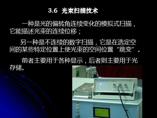
幅度大而有规律的光方向时间调制器可作光扫描器
空间调制器:光强、偏振态或相位等随空间各点而变化, 进行调制,可产生光强的某种空间分布。
A(x,y)=A0T(x,y)
或者是形成随坐标变化的相位分布 A(x,y)=A0Texp[iθ(x,y)]
y x
或者是形成随坐标变化的不同的散射状态。顾名思义, 这是一种对光波的空间分布进行调制的器件。它的英文名 称是Spatial Light Modulator(SLM)。
空间光调制器含有许多独立单元,它们在空间排列成 一维或二维阵列,每个单元都可以独立地接受光信号或电 信号的控制,并按此信号改变自身的光学性质(透过率、反 射率、折射率等),从而对通过它的光波进行调制;控制这 些单元光学性质的信号称为“写入信号”,写入信号可以 是光信号也可以是电信号,射入器件并被调制的光波称为 “读出光”;经过空间光调制器后的输出光波称为“输出 光”。实时的二维并行处理。
3.电光数字式扫描
由电光晶体和双折射晶体组合而成,其结构原理如图5所示。
图中S为KDP晶体,B为方解石双折射晶体(分离棱镜),它能使线偏振
光分成互相平行、振动方垂直的两束光,其间隔 b为分裂度,为分裂角(也
称离散角)。
纵向电光调制器及其工作原理
T
Io Ii
sin 2
2
sin
2
2
V V
上述电光晶体和双折射晶体就构成了一个一级数字扫描器, 入射的线偏振光随电光晶体上加和不加半波电压而分别占据两 个“地址”之一,分别代表“0”和“l”状态 。
空间光调制器应用软件说明(第二版)

空间光调制器应用软件说明(第二版) 一.产生输入空间光调制器的图案 (2)1.1启动产生SLM(空间光调制器)图案界面 .............................................................. 2 1.2 读入目标图 ..................................................................... . (2)1.3计算相角图 ..................................................................... .. (3)1.4添加傅里叶模板 ..................................................................... (4)1.5添加菲涅尔模板 ..................................................................... (5)1.6直接读入相角图 ..................................................................... (6)二.产生基本光学元件图案 ..................................................................... .. (7)2.1启动产生基本光学元件图案界面 ..................................................................... .... 7 2.2基本光学元件 ..................................................................... . (8)2.2.1圆孔 ..................................................................... .. (8)2.2.2二元菲涅尔透镜 ..................................................................... .. (9)2.2.3菲涅尔透镜 ..................................................................... . (9)2.2.4轴锥透镜 ..................................................................... (10)2.2.5单缝 ..................................................................... (10)2.2.6双缝 ..................................................................... (11)2.2.7二元光栅 ..................................................................... (11)2.2.8正弦光栅 ..................................................................... (12)2.2.9闪耀光栅 ..................................................................... (13)11.1SLM()如图1所示,点击左上菜单栏中“SLM图案产生”的“产生相位图”。
光调制器的用途

光调制器的用途
光调制器是一种用于调制或控制光信号的器件,其主要用途如下:
1. 光通信:光调制器可以用于调制光信号的幅度、频率和相位,以传输信息。
在光通信系统中,光调制器常用于光电转换、光信号调制和解调等关键步骤中。
2. 光传感:光调制器可以通过调制光信号的特性,实现对环境的测量和监测。
例如,通过调制光的相位或幅度来实现光纤陀螺仪、光纤压力传感器等。
3. 光储存和处理:光调制器可以用于光存储和光处理应用。
例如,在光存储器中,光调制器可用于将信息写入和读取出光介质中。
在光处理中,光调制器可以用于光信号的成型、滤波、调制和解调等。
4. 光学成像:光调制器可以用于调制光束的相位和幅度,从而在光学成像中改变图像的特性。
例如,光场调制器可以实现二维相位调制来改变光束的焦距和聚焦深度。
5. 光噪声控制:光调制器可以控制光的强度和频率,从而在光学系统中减少或抑制光噪声。
光调制器可用于光学放大器、激光器和光纤传输系统中,以提高系统的信噪比和性能。
总之,光调制器在光通信、光传感、光储存和处理、光学成像
和光噪声控制等领域中具有广泛的应用。
它们为光学技术的发展和应用提供了重要的手段和工具。
空间光调制器原理

空间光调制器原理
空间光调制器是一种利用光的相位、强度或偏振进行光信号调制的设备。
它可以将电信号转换为光信号,并对光信号进行调制,实现光通信、光传感、光计算和光存储等应用。
空间光调制器的原理可以分为两类:光学调制器和光电调制器。
光学调制器是利用物质的光学非线性效应来实现光信号调制的。
通过在光学材料中加入控制电场,可以改变材料的折射率、吸收系数或光学路径长度,从而实现对光信号的调制。
常用的光学调制器包括Mach-Zehnder插入波导调制器和热光调制器等。
光电调制器则是利用光电效应来实现光信号调制的。
光电调制器通常由光探测器和电调制器两部分组成。
光探测器将光信号转化为电信号,而电调制器则利用电信号对光信号进行调制。
常用的光电调制器包括光电晶体管、光电导和光电效应晶体等。
空间光调制器在光通信系统中起着重要的作用。
它可以将电信号转换为光信号,并调制光信号的相位、强度或偏振,实现光信号的编码、解码和传输。
同时,空间光调制器还可以用于光存储和光计算等领域,广泛应用于光学信息处理、光学传感和光纤通信等领域。
总之,空间光调制器是一种重要的光学器件,它通过光学调制或光电调制的方式对光信号进行调制,用于实现光通信、光传感、光计算和光存储等应用。
空间光调制器的工作原理及其在信息光学中的应用

空间光调制器的工作原理及其在信息光学中的应用空间光调制器(Spatial Light Modulator,简称SLM)是信息光学领域中重要的一种设备,具有广泛的应用。
本文将介绍空间光调制器的工作原理,并阐述其在信息光学中的应用。
一、空间光调制器的工作原理空间光调制器是一种能够调整光波相位、振幅或偏振等参数的光电器件。
其基本构成包括光电转换器件和控制电路。
常见的空间光调制器有液晶空间光调制器(LC-SLM)和远红外空间光调制器(IR-SLM)等。
液晶空间光调制器利用液晶分子的旋转改变光波的偏振态,从而实现对光波的调制。
其结构包括透明电极、透明基底、液晶层等。
透明电极通过外加电压改变电场,从而改变液晶分子的旋转程度,进而改变波片的相位差。
远红外空间光调制器则是利用半导体材料的特性,通过改变电压来控制光波的相位、振幅等参数。
它在远红外波段(10μm-100μm)具有较好的响应特性,并被广泛应用于红外成像、光谱分析等领域。
二、空间光调制器在信息光学中的应用1. 相位调制空间光调制器可以通过改变光波的相位差来实现相位调制。
相位调制可用于全息成像、光学信息处理等领域。
例如,在数字全息术中,利用空间光调制器可以将三维物体信息编码到二维的全息图中,实现对物体的三维重建。
2. 模拟光学系统空间光调制器可用于模拟光学系统的构建。
通过控制空间光调制器的参数,如相位、振幅等,可以模拟各种光学元件的功能。
这对于系统性能分析、光学设计和优化等方面有着重要作用。
3. 光波前校正在自适应光学系统中,空间光调制器可以用于补偿光束的像差,提高图像的清晰度和分辨率。
通过改变光波的相位和振幅分布,空间光调制器可以实现对光场的调整,从而实现补偿效果。
4. 光通信与信息传输空间光调制器在光通信与信息传输中有广泛应用。
利用空间光调制器可以实现光信号的调制、解调和编码等功能。
同时,空间光调制器也可用于光纤通信中的信号调整、波前整形等。
5. 光学陷阱与操控空间光调制器还可用于构建光学陷阱。
液晶空间光调制器及其应用ppt课件

晶相或介晶相。
液晶的三种结构
(a)向列相 (b〕近晶相 (c)胆甾相 图1 液晶的常见三种结构
.
液晶的电光效应
由于液晶分子在形状、介电常数、折射率且电导
率等方面具有各向异性的特点,当对这样的物质施
加电场后,随着液晶分子轴的排列变化和液晶分子
的流动就会发生不稳定现象,其光学特性也会发生
变化。液晶的电光效应主要包括:扭曲效应、动态
几种Holoeye空间光调制器
LC2019
LC-R720
.
LC-R1080
PLUTO
.
PLUTO型LC-SLM性能参数
.
Holoeye SLM不同型号性能参数对比
.
Holoeye空间光调制器的几个应用 (1〕螺旋位相相衬成像 在光学显微镜中,暗场或相衬方法常被用来提高物体成像的对
.
表1 常见的几种空间光调制器材料的响应时间
材料
电光晶体
GaAS (MQW或
Etalon)
时间 1ps
1ps
材料 声光(布喇
格盒)
PLZT(多 晶)
时间 1us
10us
PLZT(单晶) 1ns 粒状悬浮液 1ms
变形薄膜 磁光开关
0.5us
变形弹性材 料
1ms
1us 向列相液晶 10ms
铁电液晶 1us
散射效应、电控双折射效应、相变效应、宾主效应
等。
.
空间光调制器
空间光调制器的定义 空间光调制器〔Spatial Light Modulator,
SLMs〕是指能将信息加载于一维或者二维的光学数 据场上,以便有效地利用光的固有速度、并行性和互 联能力,并在构成实时光学信息处理、光计算和光学 神经网络等 系统中作为基本的构造单元或关键的主动器件。
空间光调制器高阈值-概述说明以及解释
空间光调制器高阈值-概述说明以及解释1.引言1.1 概述空间光调制器是一种广泛应用于光学领域的装置,它能够通过控制光的幅度、相位和偏振状态来实现光的调制和控制。
高阈值是指空间光调制器在工作过程中所能达到的最大光强,也是衡量其性能的重要指标之一。
本文将探讨空间光调制器高阈值的意义、优势以及对其的展望和总结。
通过对高阈值技术的研究和应用,可以进一步提高空间光调制器的性能和稳定性,推动其在光通信、成像等领域的应用。
文章结构部分的内容如下:"1.2 文章结构":在本文中,我们将首先介绍空间光调制器的作用,探讨其在光学领域中的重要性。
然后,我们将重点讨论高阈值在空间光调制器中的意义,分析为何高阈值是如此关键。
接着,我们将探讨高阈值的优势,以及其在实际应用中的影响。
通过深入研究与分析,我们希望能够对空间光调制器的高阈值有更深入的认识,并为相关领域的研究和发展提供新的思路和启示。
1.3 目的:本文的目的是探讨空间光调制器在高阈值下的性能表现及其潜在应用。
通过深入分析空间光调制器的作用、高阈值的意义以及高阈值带来的优势,我们将揭示其在光学通信、激光加工等领域的重要作用。
同时,本文旨在为相关研究和应用提供理论支持和实用参考,推动空间光调制器在高阈值下的进一步应用和发展。
通过本文的研究,我们可以更好地了解空间光调制器的潜力及其在光学领域的广泛应用前景。
2.正文2.1 空间光调制器的作用空间光调制器是一种重要的光学器件,其作用是通过控制光波的相位、振幅或偏振状态来实现光信号的调制。
在光通信、光信息处理、光传感等领域中,空间光调制器扮演着至关重要的角色。
首先,空间光调制器可以用于光信号的调制和调控。
通过调整其内部光栅或电场分布,可以实现对入射光波的相位、振幅或偏振的调节,从而实现信号的调制。
这种调制范围广,速度快,响应时间短,适用于高速光通信系统。
其次,空间光调制器还可用于光信息处理。
它可以对光信号进行编码解码、滤波以及空间光学变换等操作,实现光学信号的复杂处理和处理。
空间光调制器 入射光 非平行光
空间光调制器入射光非平行光空间光调制器是一种能够控制光的相位、振幅或极化状态的器件。
它通常由一个光学晶体或半导体材料制成,利用外加电压来改变光传播中的折射率,从而实现光的调制。
空间光调制器常用于光通信、光信息处理和光计算等领域。
它具有调制速度快、带宽高、噪声低等优点,因此在光纤通信系统中被广泛应用。
当入射光为非平行光时,即光束的入射角度不等于0度时,空间光调制器仍然可以正常工作。
然而,非平行光的入射会引入一些额外的问题和挑战。
首先,非平行光的入射会导致光束在空间光调制器中出现偏移。
这是由于光在空间光调制器内部传播时,会受到晶体的非线性折射率变化的影响,导致光线发生弯曲。
这种偏移现象对于一些需要高精度定位的应用来说是一个重要的问题,需要通过调整器件结构或采用补偿措施来解决。
其次,非平行光的入射会引入光束的散斑效应。
散斑是光束经过不规则结构或介质时产生的干涉现象,会导致光的相位和振幅分布不均匀。
在光调制过程中,散斑效应会降低调制的效果,并增加系统的噪声。
因此,需要对非平行光的散斑效应进行精确的建模和校正。
除了上述问题之外,非平行光的入射还会导致光在空间光调制器中的传播路径变长,从而增加光的传播损耗。
这是由于非平行光的入射角度增加,光束在晶体中的传播距离也相应增加。
为了降低传播损耗,可以选择合适的晶体材料,优化器件结构,或者采用增益介质来增强光传播的强度。
总之,非平行光的入射对空间光调制器的性能和表现会产生一定的影响。
为了解决这些问题,需要采取适当的措施和方法,包括优化设备结构、改善材料性能、设计合理的校正算法等。
通过克服这些挑战,空间光调制器可以更好地应用于实际的光学系统中,为光通信和光信息处理领域的发展提供支持。
液晶空间光调制器
2 SLM的分类
电写入的 SLM ESLM 光写入的 SLM OSLM
写入方式
调制方式
相位调制 强度调制
3 SLM的结构特点: 它是由许多基本的独立单元组成的一维线阵或二维阵列。 ①有物理边界 ②无物理边界 ③小单元可以独立改变自身光学特性
4 SLM的“三光”
写入光/信号:控制像素的光信号或者电信号。
cos2 sin2 2 2 n2 ne nm 1
则各向异性表示为:
n ne - no
施加电压后,相位差 是外加电压的函数,可以表示为
2 d 2d V, n V , a z n dz nV o 0
液晶光阀具有多层膜 结构,它由光导层和 光阻层组成的光敏层 和扭曲向列型液晶和 介质反射镜的反射式 光调制层组成,所有 膜层都加在两透明电 极之间。反射镜在这 里的作用是:将写入 光和读出光分开,这 样就可以同时进行写 入和读出。两定向层 之间的向列型液晶分 子呈45度扭曲。
液晶光阀是利用无电压时候向列型液 晶扭曲效应和外加电压大于阈值时候 的双折射效应来工作的。当无写入光 照射时光导层呈高阻状态电压主要降 落在光导层上。液晶上电压很小,不 足以引起双折射效应,液晶显示扭曲 效应。线偏振读出光两次经过液晶两 次,偏振态没有改变。通过正交检偏 器,呈现暗场。线偏振光经当有写入 光照射时候光导层呈低阻状态。液晶 上压降曾大,出现双折射效应。此时 偏振读出光被液晶调制为椭圆偏振光。 通过正交检偏器时候呈现亮场。
液晶光阀
液晶光阀是一种比较成熟的SLM,在实时光学信息处理系统中可作为实时 图像输入,转换,显示和记录的器件。是一种比较成熟的空间光调制器。具 有广泛的应用前景。
优点:结构简单,工作电压小,造价低,性能好等。 1 液晶光阀的结构和工作原理:
dmd空间光调制器激光损伤阈值
一、概述当今社会,激光技术已经广泛应用于军事、医疗、通信、工业等领域,而激光损伤阈值是评定激光设备性能的重要指标之一。
而在激光损伤阈值的研究中,dmd空间光调制器也被广泛应用。
本文将探讨dmd空间光调制器在激光损伤阈值研究中的应用。
二、dmd空间光调制器简介1. dmd空间光调制器是一种基于数字微镜片技术的高精度光电器件,它可以通过调制光的相位和振幅来实现对光的空间分布控制。
2. dmd空间光调制器具有高反射率、高光学质量、快速响应等特点,被广泛用于激光领域的研究和应用。
三、dmd空间光调制器在激光损伤阈值研究中的应用1. 激光损伤阈值是评估材料对激光辐射的耐受能力的重要参数。
传统的激光损伤阈值测试需要大量的人力物力,并且测试效率低下。
2. dmd空间光调制器可以根据需要实现对激光的空间分布进行调节,可以很好地模拟不同材料在不同激光条件下的受损情况,从而大大提高了激光损伤阈值的测试效率和准确性。
3. 通过对不同材料在不同激光条件下的损伤情况进行模拟实验,研究人员可以更加全面地了解材料的激光损伤特性,为材料的选用和激光设备的设计提供科学依据。
四、dmd空间光调制器在激光损伤阈值研究中的优势1. 高精度:dmd空间光调制器可以精确控制光的相位和振幅,可以满足不同激光损伤阈值测试的需求。
2. 高效性:相比传统的激光损伤阈值测试方法,dmd空间光调制器可以大大提高测试效率,节约时间和成本。
3. 灵活性:dmd空间光调制器可以根据实际需求灵活调整激光的空间分布,适用于不同材料在不同激光条件下的损伤研究。
五、结论dmd空间光调制器在激光损伤阈值研究中具有重要的应用前景和广阔的市场需求。
随着激光技术的不断发展,dmd空间光调制器将会在激光领域中发挥越来越重要的作用,为激光设备的性能评定和材料的选择提供更加科学的依据。
六、 dmd空间光调制器在激光损伤阈值研究中的实际应用案例在激光技术领域,dmd空间光调制器在激光损伤阈值研究中得到了广泛的实际应用。
- 1、下载文档前请自行甄别文档内容的完整性,平台不提供额外的编辑、内容补充、找答案等附加服务。
- 2、"仅部分预览"的文档,不可在线预览部分如存在完整性等问题,可反馈申请退款(可完整预览的文档不适用该条件!)。
- 3、如文档侵犯您的权益,请联系客服反馈,我们会尽快为您处理(人工客服工作时间:9:00-18:30)。
DOI 10.1007/s11141-015-9547-8Radiophysics and Quantum Electronics,Vol.57,Nos.8–9,January,2015(Russian Original Vol.57,Nos.8–9,August–September,2014)APPLICATION OF THE PHASE LIGHT MODULATOR IN THE IMAGE OPTICAL ENCRYPTION SCHEME WITH SPATIALLY INCOHERENT ILLUMINATIONA.P.Bondareva,N.N.Evtikhiev,V.V.Krasnov,∗and S.N.Starikov UDC004.932.4+004.942+535.42+535.8We describe application of the phase liquid-crystal spatial light modulator HoloEyePLUTOVISas an encoding element in the image optical encryption scheme with spatially incoherent illumi-nation.Optical encryption and numerical decryption of test images were conducted.The resultsof experiments demonstrate the efficiency of the constructed optical encryption scheme.1.INTRODUCTIONCurrently,we are witnessing the existence and intense development of the optical encryption meth-ods characterized by a high speed,simultaneous multichannel processing,and the absence of concomitant radiation in the radio-frequency band.Encryption systems in spatially coherent monochromatic light are widespread.One of the best-known systems uses the double random-phase encryption[1–5].In this case, encryption is performed in monochromatic spatially coherent light using two random phase masks.Appli-cation of random phase masks as two-dimensional encoding keys leads to the fact that such systems have a high cryptographic strength.However,because of the need to record phase,such systems require holo-graphic methods of recording and,correspondingly,complex optical schemes.Moreover,the use of random phase masks leads to a poor-quality encryption of images.To simplify the encryption schemes and improve the decryption quality,one can pass from spatially coherent to spatially incoherent radiation.In this case,recording of the encrypted image is no longer required and the holographic recording scheme becomes unnecessary.The encryption is performed by transmission of monochromatic spatially incoherent radiation from the encrypted object through a diffractive optical element,resulting in the formation of an intensity distribution described by the object image convolution with a point spread function,namely,an impulse response of the diffractive optical element in intensity[6, 7].This intensity distribution is the encrypted image recorded by a matrix photosensor.The fundamental possibility of optical encryption in incoherent light was demonstrated in[8],but using a random phase mask as the encoding diffractive optical element precluded the achievement of an acceptable decryption quality.This is because the point spread function of a random phase mask is virtually unlimited in space and significantly exceeds the size of the encrypted image.As a result,the photosensor records only the central part of the encrypted image,which leads to distortions of the decrypted image.To solve this problem,we suggest that the encoding element is not used as a random phase mask,but as a diffractive optical element having a given spatially limited point spread function,with length smaller than the size of the encrypted image.∗vitally.krasnov@mail.ruNational Nuclear Research University(NNRU),Moscow,Russia.Translated from Izvestiya Vysshikh Ucheb-nykh Zavedenii,Radiofizika,Vol.57,No.8–9,pp.693–701,August–September2014.Original article submitted November11,2013;accepted March31,2014.0033-8443/15/5708-0619c 2015Springer Science+Business Media New York619Fig.1.Block diagram of optical encryption using a diffractive optical element.The scheme of the encryption process is given in Fig.1.The object is illuminated by spatially inco-herent monochromatic light.When the radiation passes through a diffractive optical element,an intensity distribution g,which corresponds to the colvolution of the image of object f and the point spread function h of the diffractive optical element,is formed in the photosensor plane.The recorded image g is the encrypted image of object f and the point spread function h is the encoding key.As a diffractive optical element,the Fourier holograms are often used.However,the fact that the holograms have several diffraction orders impedes using them in optical numerical systems since the required encoding point spread function can be formed only in one diffraction order.An alternative application of holograms is the use of such synthesized phase diffractive elements as phase-only synthetic holograms[9], which form a single diffraction order that contains the required point spread function[10].Since the encryption is performed through a convolution,a bound is imposed on the distribution h of the Fourier spectrum amplitude of the encoding key.The spectrum of the key should overlap the spectrum of the encrypted image f;otherwise,losses of information of the encrypted image at the spatial frequencies not covered by the spectrum of the key are unavoidable in the encryption.The Fourier spectrum of a perfect key should not contain small amplitudes compared with the average level to avoid losses of information in the encryption.The main requirement for the encoding systems is that the encoding key can be changed for each portion of encrypted information.This limits the possibility of using statistical encoding elements.To implement the encryption system with a dynamically varied encoding key,for mapping of the diffractive optical element it is expedient to use spatio-temporal light modulators[11]by which the element can be changed at a rate of tens of hertz or more.This encryption scheme was proposed and tested by us in[12].The experimental results obtained in that paper demonstrated the insufficient degree of hiding of information in the encrypted images.In this regard,the present work aims at determining the reasons,their elimination,and performing experiments on optical encryption in spatially incoherent light by using a liquid-crystal spatial light modulator to form the encoding point spread function.The paper is organized as follows.In Sec.2,we describe the experimental setup.In Sec.3,we give the results of seeking and eliminating the reasons for the insufficient degree of hiding of information.In Sec.4,we give a description and the results of the experiments.The mainfindings are formulated in the Conclusions.620Fig.2.Scheme of the experimental setup for optical encryption of images in spatially incoherent light based in a phase liquid-crystal spatial light modulator.2.EXPERIMENTAL SETUP FOR OPTICAL ENCRYPTION WITH SPATIALLY INCOHERENTILLUMINATION AND THE ABILITY TO DYNAMICALLY CHANGE THE ENCODING KEYThe optical encryption scheme capable of dynamically changing the key was experimentally imple-mented by the temporal integration method[12,13],which was employed in,e.g.,incoherent acousto-optical correlators[14–16].The idea of the method is as follows.We record an image of the object moving along some encoding trajectory,which gives rise to an image described by the convolution of the image of the object and the encoding trajectory.Mathematically,this process of encoding of the image f by the discrete trajectory h can be described as follows:g(i,j)=ik=1jl=1f(k,l)h(i−k,j−l).(1)Here,g(i,j)is the brightness of an image pixel at the point with the coordinates i and j,h(i−k,j−l)is the value of the element(i−k,j−l)of the matrix of a trajectory with the coordinates i−k and j−l; the quantity h characterizes the time offinding the image at this point on the trajectory.The trajectory h forms the encoding point spread function of the optical system by analogy with the point spread function of the diffractive optical element and the encoding key.The scheme of the experimental setup for optical image encryption in spatially incoherent light based on a phase liquid-crystal spatial light modulator(SLM),which we proposed in[12],is shown in Fig.2.The radiation of a He–Ne laser(wavelength0.63μm)is collimated by lenses L1and L2.Rotating opal diffuser (ROD)breaks the spatial coherence of the radiation.The encoded scene is located in the front focal plane of lens L3.The liquid-crystal spatial light modulator HoloEyePLUTOVIS,which consists of1920×1080pixels with sizes8×8μm,is able to output256levels of the phase and is located in the rear focal plane of lens L3. Polarizers P and A are oriented so as to ensure the correct operation of the phase modulator.Lens L4forms an image of the encoded scene on the photosencor of the monochrome camera MegaPlus II ES11000with a 4008×2672pixel resolution,a10-bit analogue-to-digital converter,and the maximum signal-to-noise ratio equal to140.The modulator generates a sequence of alternating phase gratings with a sawtooth profile. Changing the modulator-mapped grating(changing their period and orientation)during the frame record621Fig.3.Image encryption:before(a)and after(b)the decrease in temporalfluctuations of the modulator phase shift.leads to the movement of the scene image on the camera photosensor.As a result,the image recorded by the camera corresponds to the convolution of the scene image and the encoding trajectory.3.ANALYSIS AND ELIMINATION OF THE REASONS FOR THE INSUFFICIENTDEGREE OF HIDING OF INFORMATION ON ENCRYPTED IMAGESThe analysis has shown that the insufficient degree of hiding of information in the encrypted images was due to significant temporalfluctuations of the phase shift during the frame mapping in the light mod-ulator[17,18].As a result of thesefluctuations,besides the desiredfirst diffraction order,the undesirable zero order was observed during the formation of each point of the point spread function.According to the measurement results,the intensity of the latter made up one-fourth of the intensity of thefirst order. Correspondingly,in the encoding point spread function used in the experiments and composed of30points, the total intensity of the zero order was about a factor of eight greater than the intensity of the other points. As a result,the recorded image can be represented as the sum of the encrypted image proper,formed by the design point spread function without the zero order,and the original non-encrypted image with brightness a factor of eight greater than the brightness of thefirst term.This is exactly the reason for the insufficient degree of hiding of information in the resulting encrypted image.The result of encryption in described conditions is given in Fig.3a.The original image stands up against the background of the encrypted one.To decrease the temporalfluctuations of the phase shift,we replaced the standard address configu-ration of the control voltage in the light modulator by the configuration we received from the producer by request.According to the measurements,changing the configuration reduced the maximum amplitude of fluctuations almost fourfold,from0.48πto0.13π.As a result,we managed to increase two times the intensity ratio of thefirst and the zero diffraction orders,from4.0to8.0.This made it possible to improve fundamentally the quality of hiding of information in the encrypted images.This was demonstrated in Fig.3:while previously the original text stood up against the background of the encrypted one(see Fig.3a),only a small number of individual characters are identified after the decrease in temporalfluctuations of the phase shift of the liquid-crystal spatial light modulator in the encrypted image(see Fig.3b).The further decrease influctuations can be achieved by using synchronization tools[18].622Fig.4.Optical encryption of the grayscale sceneimage:image of the scene to be encrypted (a ),encoding point spread function (b )and encryptedscene image (c ).4.EXPERIMENTS ON OPTICAL ENCRYPTION AND NUMERICAL DECRYPTION OF IMAGESTo demonstrate encryption by the implemented setup,we used two types of images,namely,grayscale and binary line images.In the experiments we used images with linear sizes in a range of 700to 1500pixels of the photosensor.The linear size of the encoding point spread function made up one-third of the size of the encrypted images and was chosen to hide information and provide the subsequent decryption.An example of optical encryption of the grayscale scene image by the implemented setup is shown in Fig.4.The encrypted grayscale image occupied a region of 800×780pixels on the camera photosensor.The encoding point spread function comprised 30points located on a field of 251×296samples and occupied a region of 342×403pixels.Correspondingly,the encrypted image occupied a region of 1141×1382pixels.The information content in the encrypted image was visually lost,as was expected.Image decryption was performed numerically by the inverse filtering method with Tikhonov’s reg-ularization [19].The result of numerical decryption of the grayscale scene image presented in Fig.4c is given in Fig.5a .This image,decrypted with regularization parameter equal to 10−2,is visually the best in the group of images decrypted with different parameters of the image regularization.Normalized standard deviation of decrypted image from the original can serve as the measure of quality of decrypted image [20].623Fig.5.Numerical decryption of the grayscale scene image (Fig.3c ):(a )is the image decrypted with regulariza-tion parameter equal to 10−2and (b )is the dependence of the normalized standard deviation δon Tikhonov’s regularization parameter α.Fig.6.Optical encryption of a fragment of text:(a )is the image of the text,(b )is the encodingpoint spread function,and (c )is the encrypted im-age of the text.The dependence of the normalized standard deviation of decrypted images on Tikhonov’s regularization parameter is given in Fig.5b .Despite the noisiness,the decrypted image is confidently identified.An example of optical encryption of the image of a fragment of text is given in Fig.6.The encrypted 624Fig.7.Numerical encryption of the image of a fragment of text:(a)is the decrypted image with the minimum normalized standard deviation from the original and(b)is the dependence of the normalized standard deviation δon Tikhonov’s regularization parameterα.image of a fragment of text occupied a region of1104×864pixels on the camera photosensor.We used the same encoding point spread function as in the previous case.Correspondingly,the encrypted image occupied a region of1445×1266pixels.Although a small number of individual characters are identified in the encrypted image,the encrypted text can definitely not be read.The result of numerical decryption of the image of a fragment of text(Fig.6c)is given in Fig.7a. This image,decrypted with regularization parameter equal to10−4,has the minimum normalized standard deviation on the original and is visually the best in the group of images decrypted with different regularization parameters.The dependence of the normalized standard deviation on Tikhonov’s regularization parameter is presented in Fig.7b.The decrypted image of a fragment of text is confidently read.The quality of encryption was determined by the number of nonzero points of the encoding point spread function.Due to the limited exposure of the camera,the number of points of the encoding trajectory was limited to30,which not always was sufficient for a complete hiding of encrypted information.The noise observed in the decrypted images was stipulated,first of all,by notable temporalfluctuations of the phase shift and residual nonlinear dependence of the phase shift on the level of the signal supplied.This has led to the appearance of higher diffraction orders going beyond the region of record of encrypted image.5.CONCLUSIONSThe scheme of optical decryption of images in spatially incoherent light based on a phase liquid-crystal spatial light modulator capable of dynamically changing the encoding key has been experimentally implemented.The temporal integration technique was employed to generate the encoding point spread function.Due to a fourfold decrease in the temporalfluctuations of the phase shift in the modulator(from 0.48πto0.13π),we reduced by two times the intensity of the zero diffraction order in the encoding point spread function.This ensured a sufficient degree of hiding of information in the optically encrypted images. In the optical encryption experiments,the linear size of the encoding point transfer function made up about one-third of the size of the encrypted images and was chosen to provide hiding of information and enable the subsequent numerical decryption.The decrypted text images are identified with the corresponding originals. The results of the experiments confirm the efficiency of the implemented encryption scheme with spatially incoherent illumination and the ability to dynamically change the encrypting key.The noise observed in the decrypted images are stipulated,first of all,by notable temporalfluctuations of the phase shift in the light modulator.For the further decrease influctuations and,therefore,improvement625of the encryption quality one should use synchronization of the modulator and radiation source or the recording camera.This work was supported by the Russian Foundation for Basic Research(project No.13–07–00395). REFERENCES1.P.R´e fr´e gier and B.Javidi,Opt.Lett.,20,767(1995).2. B.Javidi,A.Sergent,G.S.Zhang,and L.Guibert,Opt.Eng.,36,No.4,992(1997).3.G.T.Unnikrishnan,J.Joseph,and K.Singh,Opt.Lett.,25,No.12,887(2000).4. B.Javidi,N.Towghi,N.Naghzi,and S.C.Verall,Appl.Opt.,39,No.14,2313(2000).5. B.M.Hennelly and J.T.Sheridan,Opt.Eng.,43,No.10,2239(2004).6.R.Henao,E.Rueda,J.F.Barrera,and R.Torroba,Opt.Lett.,35,No.3,333(2010).7.M.V.Konnik and S.N.Starikov,mun.,282,No.21,4210(2009).8. B.Javidi,E.Tajahuerce,ncis,and P.Andr´e s,Opt.Lett.,26,No.10,678(2001).9.L.B.Lesem,P.M.Hirsch,and J.A.Jordan,Jr.,IBM J.Res.Dev.,No.13,150(1969).10.S.N.Starikov,V.G.Rodin,E.A.Shapkarina,et al.,Proc.SPIE,5437,301(2004).11.P.C.Mogensen and J.Gluckstad,Opt.Lett.,25,No.8,566(2000).12.N.N.Evtikhiev,V.V.Krasnov,S.N.Starikov,et al.,Proc.SPIE,8429,84291P(2012).13.V.V.Krasnov,S.N.Starikov,and P.A.Cheremkhin,Vestnik RUDN,Ser.Matem.,Inform.,Fiz.,No4,124(2011).14.H.J.Caulfield,Handbook of Optical Holography[Russian translation],Mir,Moscow,Vol.2(1984),p.584.15.N.V.Masalsky,Proc.SPIE,5066,292(2003).16.S.Kim and K.Wagner,Opt.Engineering,44,No.10,108202(2005).17. A.Hermerschmidt,S.Osten,S.Kr¨u ger,et al.,Proc.SPIE,6584,65840E(2007).18. A.P.Bondareva,V.V.Krasnov,and P.A.Cheremkhin,in:Proc.VIII Int.Conf.of Scientists andSpecialists“Optics2013,”St.Petersburg(2013),p.207.19.V.Ya.Arsenin and A.N.Tikhonov,Solutions of Ill-Posed Problems[in Russian],Nauka,Moscow(1979).20.J.R.Fienup,Appl.Opt.,36,No.32,8352(1997).626。
