FAN5068ACPI中文资料
浪潮电子信息产业股份有限公司 BIOS 设置用户手册说明书

浪潮英信服务器BIOS用户手册文档版本V2.2 发布日期2022-10-12版权所有© 2021-2022浪潮电子信息产业股份有限公司。
保留一切权利。
未经本公司事先书面许可,任何单位和个人不得以任何形式复制、传播本手册的部分或全部内容。
环境保护请将我方产品的包装物交废品收购站回收利用,以利于污染预防,共同营造绿色家园。
商标说明Inspur浪潮、Inspur、浪潮、英信是浪潮集团有限公司的注册商标。
本手册中提及的其他所有商标或注册商标,由各自的所有人拥有。
内容声明您购买的产品、服务或特性等应受浪潮集团商业合同和条款的约束。
本文档中描述的全部或部分产品、服务或特性可能不在您的购买或使用范围之内。
除非合同另有约定,浪潮集团对本文档的所有内容不做任何明示或默示的声明或保证。
文档中的示意图与产品实物可能有差别,请以实物为准。
本文档仅作为使用指导,不对使用我们产品之前、期间或之后发生的任何损害负责,包括但不限于利益损失、信息丢失、业务中断、人身伤害,或其他任何间接损失。
本文档默认读者对服务器产品有足够的认识,获得了足够的培训,在操作、维护过程中不会造成个人伤害或产品损坏。
文档所含内容如有升级或更新,恕不另行通知。
技术支持客户服务电话:4008600011地址:中国济南市浪潮路1036号浪潮电子信息产业股份有限公司邮箱:***************邮编:250101前言摘要本手册介绍服务器BIOS设置的相关内容。
目标受众本手册主要适用于以下人员:●技术支持工程师●产品维护工程师建议由具备服务器知识的专业工程师参考本手册进行服务器运维操作。
符号约定在本文中可能出现下列标志,它们所代表的含义如下。
图标说明如不当操作,可能会导致死亡或严重的人身伤害。
如不当操作,可能会导致中度或轻微的人身伤害。
如不当操作,可能会导致设备损坏或数据丢失。
为确保设备成功安装或配置,而需要特别关注的操作或信息。
对手册内容的描述进行必要的补充和说明。
华硕A68HMK用户手册

C9808_A68HM_Series_Manual.indb 3
請用剪刀沿虛線剪下
A. 超過華碩提供的質保有效期的主板、顯卡產品。 B. 因遇不可抗拒外力(如:水災、火災、地震、雷擊、颱風等)或人為之操作使用不慎造 成之損害。 C. 未按產品說明書條例的要求使用、維護、保管而造成的損壞。 D. 用戶擅自或請第三方人員自行檢修、改裝、變更組件、修改線路等。 E. 因用戶自行安裝軟件及設置不當所造成之使用問題及故障。 F. 本公司產品序列號標貼撕毀或無法辨認,塗改保修服務卡或與實際產品不符。 G. 其他不正常使用所造成之問題及故障。 五、 技術支持及維修服務: 1. 我們建議您先登錄華碩官方會員網站(/signup.aspx?lang=zhcn&site=global),對您購買的華碩產品進行在線註冊,註冊後您將會定期得到我們發送 的產品信息以及技術資料; 如果您在使用華碩產品的過程中遇到問題,您可以首先查閱用戶手冊,尋找答案; 您亦可訪問華碩中文網站技術支持頁面(/support/)查詢到相 應的技術支持信息與常見問題排除; 登錄我們的在線技術支持服務區進行咨詢(/eservice/techserv. aspx); 也歡迎您撥打華碩客戶關懷中心 7x24 小時免費技術支持專線 400-620-6655,由我們 的在線工程師為您提供服務; 如果您使用的華碩產品由於硬件故障,需要維修服務,您可以直接聯繫您的經銷商,通 過經銷商及遍佈全國的華碩展示服務中心進行後續相應的檢修服務。 無論通過何種方式來尋求技術服務,請您務必要明確告知您使用的產品型號、BIOS 版 本、搭配之硬件、詳細的故障現象等,以利於華碩工程師能幫助您更加準確快速地判斷 出故障的原因。
內華碩就本用戶手冊不提供任何明示或默示的擔保及保證包括但不限于商業暢銷性特定目的適用性未侵害任何他人權利及任何使用本用戶手冊或無法使用本用戶手冊的保證且或因不可歸責于華碩的原因而無法使用本用戶手冊或其任何部分而可能產生的衍生附帶直接間接特別懲罰或任何其它損失包括但不限于利益損失業務中斷資料遺失或其它金錢損失負責不論華碩是否被告知發生上述損失之可能性
APC MGE Galaxy 5000中文手册介绍

容许的存放温度范围为-20° C到+45° C。 如果UPS长期失电,我们建议您每月至少一次为UPS加电24小时。这就为电池充电,从而避免了可能的无可挽救的损失。 UPS设计用于一般气候及环境运行条件,包括海拔高度、环境运行温度、相对湿度、环境运输条件及环境存放条件。 在给定的限制范围内使用UPS确保了其正常运行,但可能会影响某些组件的使用寿命,特别会影响电池及其自控能力。根据将集 成电池放电的需要限定UPS的最大存放时间。 异常的运行条件可验证UPS高效的特殊设计或保护措施: -有害烟尘、磨屑, -湿气、蒸汽、盐雾、坏天气或油滴, -爆炸性粉尘及气体混合物, -气温大幅度变化, -通风不好, -来自其他源的传导热或辐射热, -冷却水含酸性物质或杂质,会使接触水的变流器部件出现氧化层、沉渣、电蚀或腐蚀, -强电磁场, -辐射水平高于常规环境, -菌类、昆虫、寄生虫等, -电池运行条件。
所有Galaxy 5000系列产品均受专利保护。这些产品均采用了其它制造商所没有的MGE UPS SYSTEMS原装技术。 考虑到要有关标准和技术方面的改进,设备修改时将不作另行通知。除非经MGE UPS SYSTEMS确认,否则对技术特性和尺寸的有关说明概不 负责。 未经MGE UPS SYSTEMS书面许可,不得复制本文件。授权的复印件必须标上“Galaxy 5000 n° 3400181300”。
XG8资料

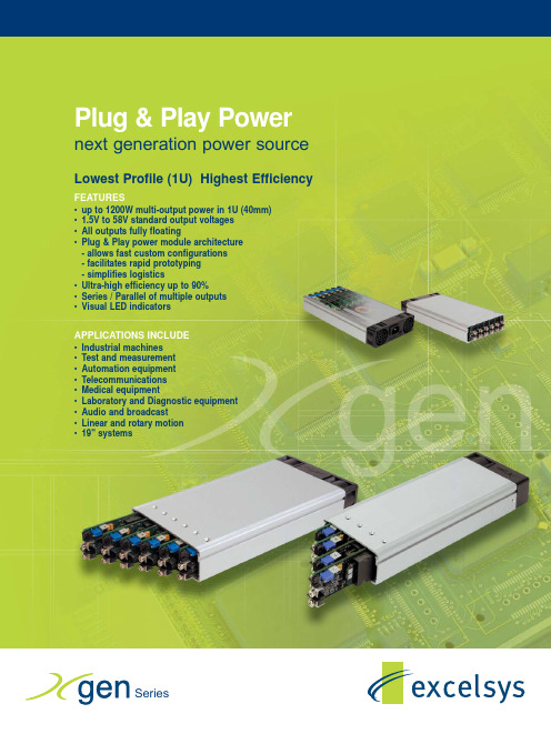
Plug & Play Power next generation power source Lowest Profile (1U) Highest EfficiencyFEATURES•up to 1200W multi-output power in 1U (40mm)•1.5V to 58V standard output voltages•All outputs fully floating•Plug & Play power module architecture- allows fast custom configurations- facilitates rapid prototyping- simplifies logistics•Ultra-high efficiency up to 90%•Series / Parallel of multiple outputs•Visual LED indicatorsAPPLICATIONS INCLUDE•Industrial machines•Test and measurement•Automation equipment•Telecommunications•Medical equipment•Laboratory and Diagnostic equipment•Audio and broadcast•Linear and rotary motion•19" systemsExcelsys brings over 20 years experience of modular power supply development and applications together with the most modern product development and design techniques in the revolutionary Xgen series.The Xgen series brings OEM power supplies to a new paradigm, combining technical excellence with logistics simplicity to fully resolve all the concerns regularly expressed by users of multiple-output power supplies. Xgen continues the Excelsys tradition of providing an instant, no compromise power solution for any application where a unique set of voltage and current requirements is needed.Excelsys Development and Design MethodologyExcelsys has applied the most modern and rigorous processes and design techniques to development of the Xgen product range.Too much heat generated in your OEM equipment?Difficult to maintain your equipment at the right temperature?Xgen has industry-unrivalled efficiency, exceeding 90% !! This means that less than half of the amount of waste heat is created in comparison to conventional multiple output power sources with efficiencies of 80%and lower. It also guarantees increased reliability.Now, that’s a cool power supply!Not enough space available in your OEM equipment?Is space at a premium, making design and manufacture difficult and compromised?X gen has industry-unrivalled power density for a full functionality ac/dc power supply, at 15W/in 3. Check itout! You can get 1200W of multiple-output power source in 1U rack space - Xgen dimension: 40.4mm! It’s so compact, you’ll hardly notice it, once installed, and it leaves plenty more space for your other components and general accessibility.Now, that’s a discreet power supply!Need a custom power supply in a hurry?Xgen is a true Plug & Play multiple-output power supply. Any one of more than 30 million configurations can be assembled anywhere, in under 5 minutes, from standard, volume-produced modules. This is the new-paradigm: a custom power supply available in 5 minutes from standard parts.Now, that’s a new paradigm power supply!Worried about meeting all relevant standards - EMC, Safety, etc?Xgen series models are fully compliant with all relevant standards. X cite , X lite , X hite and X qite models meet the requirements of EN60950, UL60950, CSA22.2, EN61000-3-x and EN61000-4-x. Additionally X vite and X mite models meet the requirements of EN60601-1 and UL2601 for medical applications.Now, that’s a re-assuring power supply!Looking for a cost-effective long term solution for all your power supply requirements?Xgen is configured from standard component parts that are manufactured in volume in a world class manufacturing facility. This allows Excelsys to provide you with all the benefits of Xgen at a world class competitive price. Call Excelsys or one of our distributors and find out for yourself.Now, that’s an excellent value power supply!EFFICIENCYSPACE CUSTOM POWERSTANDARD APPROVALSCOST-EFFECTIVEA world-class Stage-Gate TM development process ensures that a holistic approach to development and design is guaranteed, with optimised outcomes built in from the start in respect of customer needs, manufacturing, support and logistics. The Stage-Gate TM process provides the framework for efficient and effective teamwork within Excelsys as well as between Excelsys and its design partners.The development-specific processes are supplemented by the company-wide processrequirements of ISO9001:2000, in particular in the ISO9001:2000 designated area of ‘Product Realisation’.Excelsys was an early adopter of and is fully approved to this latest, upgraded ISO9001:2000 standard.As well as design laboratory testing,Excelsys has applied exhaustive HALT testing and field prototype testing to development of Xgen. Highly Accelerated Life T esting ensures that design margins are more than sufficient to provide insensitivity to manufacturing variability and to maximise field reliability.AC FailOpen collector signal indicating that the input voltage has failed or is less than 80Vac. This signal changes state giving 5mS of warning before loss of output regulation. See Xgen series Designers’Manual for full specifications.Temperature Alarm (Option 01)Open collector signal indicating excessive powerPac temperatures due to fan failure or operation beyond ratings. This signal is activated at least 10ms prior to system shutdown.Fan Fail (Option 01)Open collector signal indicating that at least one of the system fans have failed. This does not cause system shutdown.Power GoodOpto-isolated output signal indicates that the powerMod is operating correctly and output voltage is within normal band.Indication LEDsEach powerMod has a visual indicator to identify that it is operating within normal ratings. Very useful for system diagnosis.Signal Connector PinoutPin J2 (powerPac )J3 (powerMod TYPE A)**J3 (powerMod Type B)**1common +sense +pg (V2)2+5V bias -sense -pg (V2)3V trim inhibit (V2)4ac fail I trimcommon (V2)5fan fail*+inhibit/enable +pg (V1)6global enable -inhibit/enable -pg (V1)7temp alarm*+power good inhibit (V1)8global inhibit-power goodcommon (V1)*Option 01 only**See individualpowerMod datasheetsVoltage Adjustment - LocalThe multi-turn potentiometer that adjusts each output within the specified range may be accessed via the output panel of the power supply. Clockwise rotation increases output voltage. Resolution is approximately 5% of nominal voltage (Vnom) per turn.Voltage Adjustment - Remote (resistive / electronic)The output voltage may be adjusted or trimmed by means of an externalresistor or potentiometer network connected to the Vtrim pin. Linear Electronic programming is also possible and may be implemented according to theformula Vout = K Vcontrol. See Xgen series Designers’Manual for full details.ParallelingT o achieve increased current capacity, simply parallel outputs using the standard parallel links. Excelsys ‘wireless’sharing ensures that current SeriesingT o achieve increased output voltages, simply series outputs using standard series links, paying attention to the requirements to maintain SELV levels if required in your system.Remote SensingWhen the load is remote from the power supply, the remote sense pinsmay be used to compensate for drops in the power leads. Where the power cabling contributes significant dynamic impedance, see Xgen series Designers’Manual.Bias VoltageA SELV isolated 5V (always on) bias voltage rated at 250mA is provided on J2 to facilitate miscellaneous control functions.Current Limit AdjustmentThe output current limit setting may be adjusted (downwards only) by means of an external resistor connection to the I trim pin.Inhibit/EnableInhibiting may be implemented either globally or on a per module basis (powerPac or powerMod inhibiting). Reverse logic (Enabling) may also be implemented, see Xgen series Designers’Manual.Model Slot A Slot B Slot C= standard; ‘P’= preset Use ‘0’for unused slots.Factory use only }Configured Units may be specified and ordered using the partnumbering system shown opposite. For example, part numberXVC123400-01 specifies the following 1000W medical power supply.• 2.5V @ 50A 5V @ 40A 12V @ 20A 24V @ 10A•Thermal signals suite fitted to powerPacAccessories may be ordered directly using the part numbers shown.PartPart No.Left Slot Cover XB1Note that unused slots Inner Slot Cover XB2should be fitted with Right Slot Cover XB3appropriate slot covers.Series LinkXS1Parallel LinkXP1powerPacs may be ordered directly using the model number shown in thetables followed by the appropriate option code suffix. E.g. XVB-01 is thepart number for 700W powerPac with medical approval and thermal signals. powerMods may be ordered directly using the model numbers shown inthe powerMod table. E.g. Xg2 is the part number for a 5V 40A module.powerKits consist of application specific powerPacs and a selection ofpowerMods packaged in a convenient carry case. Particularly useful forsytems designers. See powerKit datasheet.Xgen Option Codes01Thermal Signals02Reverse Fan (not available on 1200W models)Preset Units Units are shipped with nominal output voltages unless presetting is specified.Excelsys can preset units to your exact requirements, through use of appropriate parallel and series links and through voltage adjustment to specific preset levels. See for more details.On-line Configuration and OrderingNow build your Xgen product on-line using our configuration wizard. Simply enter your Volts and Amps requirements and the wizard will do the rest.Family MODEL WattsX citeXCA 400W XCB 700WXCC 1000W XCD1200WpowerPacs (6slot package, 127mm wide)Family MODEL Watts X liteXLA 200W XLB 400W XLC600WpowerPacs(4slot package, 89mm wide)The X hite family is designed specifically for extended temperature applications fully specified from -20o C to +70o C with no deratingThe X qite family is designed specifically for acoustic sensitive applications.Doc. 40031 rev. 01 04/05Europe/AsiaExcelsys Technologies Ltd t: +353 1 8900933Swords Business Park f: +353 1 8901358Swords, Co. Dublin e: sales@IRELANDNorth AmericaExcelsys Technologies t: (972) 771 4544519 Interstate 30, #309f: (972) 421 1805Rockwall, TX 75087e: salesusa@USAp o wer P a c p o w e r Mo d s。
D-MA78GK 说明书

UG1
北桥控制芯片
IC 芯片
IDE1
1 个 IDE 通道
40PIN 接口
BT1
锂电池插座
电池插座
FDD
软盘驱动器接口
34PIN FDD 接口
FUSB1/FUSB2
可扩展 USB 接口
9PIN 扩展接头
IR1
红外线接口
3PIN 插头
FPANEL
前面板开关和指示灯
9PIN 插
9PIN 插头
JSPDIF
SPDIF 设备接口
5PIN 插头
SPEAKER1
喇叭控制接口
4PIN 插头
SATA1-SATA6
六个 Serial ATA 通道
7PIN 插头
JUSB1/JUSB2
USB 设备开机跳线
3PIN 跳线
JBAT
清除 CMOS 跳线
3PIN 跳线
JBIOSSLC
双 BIOS 开关(可选)
a.液体已经渗入您的设备中。 b.设备长时间暴露于湿气之中。 c.设备不能正常工作或您不能依照用户手册的描述让本设备工作。 d.设备跌落并已损坏。 e.设备具有明显的损坏迹象。 10.不允许将设备放置在潮湿或无限制的环境中,存储温度超过 60℃,将会引起设备的损坏。 * 注意: 如果设备上的某些标签脱落,将可能失去质保的凭据。
*上述附带配件规格仅供参考,实际规格以实物为准,丹丁科技保留修改之权利。 -6-
D-MA78GK 主板配置图
-7-
主板部件一览表
元器件
用途
描述
PCIE
加速图形卡接口
PCI EXPRESS16X 插槽
PCI1-PCI2
2 个 32 位 PCI 插槽
ACPI 状态 S0-S5

ACPI 就是Advanced Configuration and Power Interface 的缩写的缩写,,意思是意思是““高级配置与电源接口级配置与电源接口””。
这是英特尔这是英特尔、、微软和东芝共同开发的一种电源管理标准微软和东芝共同开发的一种电源管理标准。
ACPI 可实现以下功能:1、用户可以使外设在指定时间开关;2、使用笔记本电脑的用户可以指定计算机在低电压的情况下进入低功耗状态,以保证重要的应用程序运行;3、操作系统可以在应用程序对时间要求不高的情况下降低时钟频率;4、操作系统可以根据外设和主板的具体需求为它分配能源;5、在无人使用计算机时可以使计算机进入休眠状态,但保证一些通信设备打开;6、即插即用设备在插入时能够由ACPI 来控制。
不过,ACPI 和其他的电源管理方式一样,要想享受到上面这些功能,必须要有软件和硬件的支持。
在软件方面,Windows 98及其后续产品和Windows 2000都对ACPI 给予了全面的支持;硬件方面比较麻烦,除了要求主板、显卡和网卡等外设要支持ACPI 外,还需要机箱电源的配合。
电源在提供5伏电压给主板的同时,还必须使电流稳定在720毫安以上才可以,这样它才能够实现电脑的“睡眠”和“唤醒”。
ACPI 共有六种状态,分别是S0到S5,它们代表的含义分别是:S0--实际上这就是我们平常的工作状态,所有设备全开,功耗一般会超过80W;S1--也称为POS(Power on Suspend),这时除了通过CPU 时钟控制器将CPU 关闭之外,其他的部件仍然正常工作,这时的功耗一般在30W 以下;(其实有些CPU 降温软件就是利用这种工作原理)S2--这时CPU 处于停止运作状态,总线时钟也被关闭,但其余的设备仍然运转;S3--这就是我们熟悉的STR(Suspend to RAM),这时的功耗不超过10W;S4--也称为STD(Suspend to Disk),这时系统主电源关闭,但是硬盘仍然带电并可以被唤醒;S5--这种状态是最干脆的,就是连电源在内的所有设备全部关闭,功耗为0。
58系列中文使用手册

58系列热敏打印机目录目录 (1)一、说明 (2)1.1安全警告 (2)1.2注意事项 (2)二、概述 (3)主要特点 (3)三、技术规格说明 (3)四、打印机的安装与操作 (6)4.1打印机拆封 (6)4.2打印机连接方法 (6)4.3纸卷的安装 (7)4.4蓝牙的配对及打印(仅对58BU打印机有效) (8)4.5使用蓝牙接口打印(仅对58BU打印机有效) (8)五、打印机的开关、按键及指示灯 (8)5.1电源开关 (8)5.2按键及指示灯 (9)六、打印机自检测 (9)七、打印机的串行接口 (10)八、打印机的并行接口 (11)九、打印机的以太网接口 (12)十、打印机的钱箱接口 (12)十一、清洁打印机 (13)11.1清洁打印头 (13)11.2清洁传感器 (13)11.3清洁打印胶辊 (13)十二、清除卡纸的方法 (14)十三、故障排除 (14)13.1控制面板上的指示灯不亮 (14)13.2指示灯指示正常,但打印机不打印 (14)十四、打印机的驱动 (15)一、说明58系列打印机是POS直接热敏式票据打印机,操作简单,其性价比高,广泛应用于商场超市、医院、餐厅、银行、加油站、路桥收费等领域。
安全须知在操作使用打印机之前,请仔细阅读下面的各项内容并严格遵守使用。
1.1安全警告警告: 不要触摸打印机的切纸刀或撕纸刀。
警告:打印头为发热部件,打印过程中或打印刚结束时,不要触摸打印头以及周边部件。
警告:不要触摸热敏打印头表面和连接件。
以免静电损坏打印头。
1.2注意事项(1)打印机应安装在稳固的地方,避免将打印机放在有振动和冲击的地方。
(2)不要在高温、湿度大以及污染严重的地方使用和储存打印机。
(3)将打印机的电源适配器连接到一个适当的接地插座上。
避免与大型电机或其它能够导致电源电压波动的设备使用同一插座。
(4)避免水或导电的物质(例如:金属)进入打印机内部,一旦发生,应立即关闭电源。
(5)打印机不得在无纸的状态下打印,否则将严重损害打印胶辊和热敏打印头。
E5810A中文资料(agilent)中文数据手册「EasyDatasheet - 矽搜」

防护
1年
网络协议 尺寸
见E5810A用户手册支持网络
协议和功能
长度,宽度,和高度
211毫米宽x230毫米深部X41毫米高 (1U高度,1/2机架)
重量 环境规格
1.6千克
运行环境
0°C至55°C
工作湿度
高达90%,在40℃非冷凝
存储环境
-40°C至+ 70°C
存储湿度
高达90%在65℃下非冷凝
* Additional detail and information in the Declaration of Conformity
最大数据速率
超过900 KB / S-GPIB端口 115 KB / S-RS-232端口
RS-232波特率
300, 1200, 2400, 4800, 9600, 19200, 38400, 57600, 115200 b/s
RS-232数据流控制
无,RTS / CTS,XON / XOFF,DTR / DSR
系统使用 对于系统环境中,可以安装在机架上 E5810A网关.机架安装套件(选项 100)允许两个设备被放置侧由 端在一个机架宽度.凭借其内置电源 ,没有额外电源模块安装.
有关其他信息和图形见第7页.
4
充分利用局域网
技术为您GPIB
仪器和测试 系统
E5810A技术规范
一般要求
最低系统要求 (客户端计算机)
特征
•使用标准USB和IEEE 488接口
•最大GPIB传输速率 850多KB /秒
最适合 •最简单GPIB连接 •笔记本电脑GPIB
连接
快 速 连 接 GPIB仪 器 和 轻 松 地 下 载 到 电 脑 USB端 口
- 1、下载文档前请自行甄别文档内容的完整性,平台不提供额外的编辑、内容补充、找答案等附加服务。
- 2、"仅部分预览"的文档,不可在线预览部分如存在完整性等问题,可反馈申请退款(可完整预览的文档不适用该条件!)。
- 3、如文档侵犯您的权益,请联系客服反馈,我们会尽快为您处理(人工客服工作时间:9:00-18:30)。
REV. 1.0.0 05/26/04AN-6006FAN5068 Component calculation andsimulation toolsBackground / OverviewTo simplify designs using the FAN5068 DDR/ACPI control IC, Fairchild provides:•An Excel workbook to calculate recommended external component values and •A continuous time behavioral model of the modulator that runs in PSPICE A/D v 9.1 or above. The model is small enough to run under Cadence's Orcad Lite Edition (includes Orcad Capture and PSPICE A/D), which can be ordered on CD or may be downloaded at: /downloads/demo/default.aspInformation on the FAN5068, including the datasheet can be found on: /pf/FA/FAN5068.htmlThis package of design aids (including this document) is can be downloaded from:/collateral/AN-6006.zip .To install, copy AN-6006.ZIP to an empty folder (e.g. “FAN5068Design”). Then unzip AN-6006.ZIP into that folder.Recommended design procedure:1. Use the spreadsheet (FAN5068 Design calculation aid.xls ) to calculate the output filter using the “OutputFilter” tab.2. Use the “Main Sheet” tab of the spreadsheet to calculate the other component values once you have selected theoutput L and C.3. Use the “Compensation” tab to design the compensation network.4. Input the values you have selected into the PSPICE model. Generate a Bode plot by simulating with the“application circuit-ac sweep” simulation profile. Make sure to simulate over the corners of VIN and IOUT for your application.5. Once you are satisfied with the small signal stability, you can view the transient response by simulating usingthe “application circuit-transient response” simulation profile. Be sure the follow the instructions at the bottom of the Application Circuit, Page 1 sheet for resetting RLOAD before simulating transient response.Design Calculation Spreadsheet: FAN5068 Design calculation aid.xls For instructions on the use of this spreadsheet, see the “Instructions” tab of the spreadsheet.PSPICE Simulation ModelThe simulation model is a sampled data continuous time model, which is adapted from Ray Ridley and Dennis Feucht's modeling work for current mode controllers 1,2,3. It is set up to provide a bode plot where the red trace is Phase Margin (in degrees) and the green trace is gain (in dB). For stable response, we recommend at least 45° of phase margin when the gain crosses 0dB. The model also provides transient response using a pulsed current source (I1) as the load. The IC’s error-amp behavioral model is based on Ray Kendall’s Macromodelling article in EDN. 4 To run the model start Capture (9.1 or higher), open FAN5068.opj (this is the "project" file for Capture). Double click on Page 1 Under .\fan5068.dsn\Application Circuit.Figure 1. FAN5068.OPJ projectThe parameters for this model are entered in the "Parameters" block on the lower left-hand corner of the schematic. As such, there should be no need to edit the schematic itself.Double click on any parameter in that block to set the values in the schematic. Once the schematic is set up, F11 (function key) will display the Bode plot.To choose between Bode plot (AC small signal) and Transient response, go to the project window and right click the appropriate model. If you are simulating for transient response, be sure to set up RLOAD. You will know if you forgot this step, as the inductor current [I(L1)] trace will be much higher (probably beyond the Y axis limit) than the pulse load current [I(I1)].Alternately, from the schematic view, select the type of simulation profile from the drop-down box as shown below.Figure 2. Simulation profile select drop-downTroubleshooting the plot windowSome older versions of PSPICE may not automatically load the probe settings (which are contained in the *.prb files). These settings define the XY axis settings, trace colors, and which signals are displayed. If you run a simulation and the probe window has no trace, then add a trace, and input the expressions for the signals to plot: Gain: DB(V(Out)/V(Sig)) Phase: P(V(Out)/V(Sig))Copy and paste these expressions into the add trace window as shown below. The also schematic contains the expressions for the BODE plot in the lower right hand cornerREV. 1.0.0 05/26/0423 REV. 1.0.0 05/26/04Figure 3. Tips for adjusting probe window settings and adding tracesFigure 4. Adding the trace (Gain example)References:1Ray Ridley, An Accurate and Practical Small-Signal Model for Current-Mode Control, 1999, /downloads/curr.pdf2Dennis Feucht, The Tymerski Switch Model,/eexpert/dfeucht/dfeucht036.html3Dennis Feucht, Basic Power Converter Configurations,/eexpert/dfeucht/dfeucht037.html4Ray Kendall, Modular macromodeling techniques for Spice simulators, EDN, March 7, 2002 /ednmag/contents/images/198891.pdfREV. 1.0.0 05/26/044。
