GRM188C70G225K中文资料
海德汉光栅尺技术参数(用于NC数控机床)(HEIDENHAIN)
用于NC数控机床
2007年6月
更多信息,请访问 或来函索取。
产品样本: • 敞开式直线光栅尺 • 内置轴承角度编码器 • 无内置轴承角度编码器 • 旋转编码器 • HEIDENHAIN后续电子设备 • HEIDENHAIN数控系统 • 机床检测和验收测试测量系统
扫描单元
密封条
安装板
LC 183封闭式直线光栅尺结构示意图
DIADUR 光栅尺
光源
光电池
5
选型指南
纤细外壳的直线光栅尺
纤细外壳的直线光栅尺主要用于安装空间 有限的地方。如果使用安装板或固定元件, 可实现较大测量范围和支持更高加速度 载荷。
绝对式直线光栅尺 • 玻璃光栅尺
高重复性增量式 直线光栅尺 • 钢光栅尺 • 信号周期小
光栅尺栅距越小,光电扫描的衍射现象越严 重。HEIDENHAIN公司的直线光栅尺采用两 种扫描原理:
• 成像扫描原理,用于20 µm和40 µm栅距 光栅尺。
• 干涉扫描原理,用于栅距8 µm甚至更小 光栅。
成像扫描原理 简单的说,成像扫描原理是采用透射光生成 信号:栅距相同或相近的光栅尺和扫描光栅 彼此相对运动。扫描光栅的基体是透明的, 而作为测量基准的光栅尺可以是透明的也 可以是反射的。
带距离编码参考点光栅尺或编码器,其绝对 参考点位置通过累计两个参考点间信号周 期数并用以下公式计算:
P1 = (abs B-sgn B-1) x
N 2
+ (sgn B-sgn
D) x
abs MRR 2
其中: B = 2 x MRR-N
和:
N
P1 = 信号周期中代表移过第一个参考点
的位置
D
abs = 绝对值
海南曼姆全系产品介绍说明书
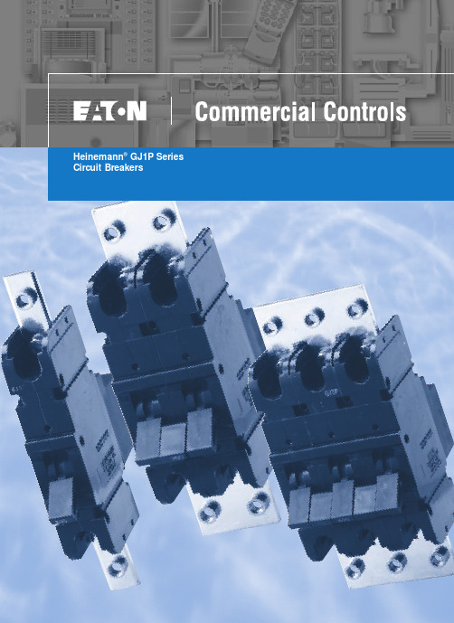
Heinemann®GJ1P Series Circuit BreakersDESCRIPTIONOptional Low-Voltage Shunt for Current MeteringEaton Corporation’s Cutler-Hammer series of Heinemann GJ1P breakers offer high quality circuit protection for DC applications from 100 to 1200 Amperes.Their precisely tailored time delays and ability to interrupt high currents makes them ideally suited for critical applications. On overloads exceeding 1000 – 1400% of rating, there is no intentional time delay and the breaker interrupts currents of as much as 25,000 A at 65V DC.An optional shunt (25 or 50millivolt full scale) permits metering of current. Since the shunt output is low voltage,light-gauge wiring can be used from shunt to meter.Indication may be displayed inpercent, watts, safe/danger or other dial calibrations. In addition, the busbar is available in two versions:Standard Size and Reduced Size. Contact your Eaton Sales Representative for more information.Precision Current Equalization (PCE) Circuit BreakersGJ1P breakers rated 250 to1200 A are built in parallel construction. Conventional parallel pole breakers can experience uneven current distribution because of variations in internalresistances. This condition can result in nuisance tripping since the higher current in one parallel branch has the same effect as an overload on the sensing element in that branch. Proprietary Precision Current Equalization (PCE)circuit breakers, on the other hand, allow for differences in internal resistances byautomatically distributing the current equally through the parallel current sensing elements, minimizing the danger of nuisance tripping.The UL listed series GJ1P (UL489) models are available in a choice of fast, medium or slow response times to accurately match load conditions. They can be ordered in “series trip ”, “mid-trip ” and “switch only ”constructions and are available front- or back-mounted, front- or back-connected, with optional auxiliary switches for signaling.HYDRAULIC-MAGNETIC BENEFITSThe magnetic/hydraulic load-sensing and time delaymechanisms used in GJ1P breakers are insensitive to changes in ambient or enclosure temperature.Therefore, GJ1P circuitbreakers are suited for service conditions encountered in telecommunications,transportation, air conditioning and other outdoor or “heat-loaded ” equipment.SPECIFICATIONSStandard Current Ratings:100, 125, 150, 175, 200, 225,250, 300, 350, 400, 450, 500,600, 700, 800, 900, 1000,1100, 1200 A.Standard Maximum Voltages:160V DC up to 700A65V DC from 701 to 1200A Breakers will be labeled with standard maximum (UL) voltage unless otherwise specified.Special Current Ratings:Any integral rating between 100and 1200 A DC. Consult factory for ordering information and metering shunt restrictions.Interrupting Capacities:UL Listed:10,000 A @ 160V DC 25,000 A @ 65V DC Non-UL:14,000 A @ 160V DC.Operating Temperature Range:-40°C to +85°C.Approximate Weight:1-pole (100-225A) 1.13kg (2.5lbs)2-pole (250-400A) 2.27kg (5lbs)3-pole (450-700A) 3.40kg (7.5lbs)4-pole (701-800A) 4.54kg (10lbs)5-pole (801-1000A) 5.67kg (12.5lbs)6-pole (1001-1200A) 6.80kg (15lbs)Weight may vary based on shunt and busbar.APPROVALSUL Listing:GJ1P breakers are UL listed per UL489. For CSA certification,consult application engineering.Description . . . . . . . . . . . . . .2Specifications . . . . . . . . . . . .2Approvals . . . . . . . . . . . . . . .2Time Delay Characteristics . . .3Dimensions . . . . . . . . . . . .4-5How to Order . . . . . . . . . . .6-7Additional Products. . . . . . . . .8TABLE OF CONTENTS PageHEINEMANN ®CIRCUIT BREAKERSGJ1P Series Circuit Breakers(100-1200 Amperes DC)2Heinemann is a registered trademark of the Eaton Corporation, Commercial Controls Business Unit.100150.01.001.1110100100010,000200300400500600700800900100011001200125C u rv e 1C u rv e 2C u rv e 3Current – Percent of Ampere RatingT r i p T i m e – S e c o n d sDC CURVES100150.01.001.1110100100010,000200300400500600700800900100011001200125Current – Percent of Ampere RatingT r i p T i m e – S e c o n d sINSTANT DELAY DC CURVE PPERCENT OF RATED CURRENT VS. TRIP DELAY AT 25ºCTIME DELAYCHARACTERISTICSTime delay, in all models,is inversely proportional to the magnitude of the overload, adjusting automatically to limit transient power to the load. On overloads exceeding 1,000 –1,400%, the circuit breaker trips without any deliberately imposed delay.Curve 1.Standard time delayis furnished unlessanother optional delay is specified. It is thepreferred characteristic for use where the load is composed of both resistive and inductive components.Curve 2.Medium time delayis for general usein mixed (inductive and resistive) circuits where the breaker rating is matched to the current carrying capacity of the mains.Curve 3.Short time delaypermits a very brief delay period before tripping.Curve P .Non-time delay breakersare available forapplications which cannot tolerate even brief transient overloads.These breakers have no time delay mechanism other than that imposed by the coil self-inductance and the inertia of the mechanism.Tripping specificationsThe time delay curves depict breaker response time vs. percent of rated load with no preloading.The function is plotted at an ambient temperature of 77°F (25°C) with the breaker in a vertical or wall-mounted position.Series GJ1P circuitbreakers will carry 100%of rated load continuously.Both time delay and non-time delay breakers may trip between 101%and 125% of rated load,and must trip at 125%and above.3% (sec)Delay 100%125%200%400%600%800%1000%Delay Max.1no trip 1100150206 1.7.065Delay Min.1no trip 110224 1.1.01.008Delay Max.2no trip 110153.8.28.055Delay Min.2no trip 12 2.5.5.18.01.008Delay Max.3no trip 10.8.19.08.047.038Delay Min.3no trip.44.13.03.015.01.008STANDARD FRONT-CONNECTED CONSTRUCTIONWire Range #6 to 250 MCM74.59(2.938)76.20(3.000)Aux. Terminals, Male Type Molex 02-09-2101, Model 1190-T(See Illustrations for Combinations)Shunt Terminals, Female TypeMolex 02-09-1101, Model 1189-T37.69(1.484)42.84(1.687)0.99 (0.390)71.42(2.812)#10-32 Inserts (4 Places)38.10(1.500)19.05(0.750)19.05(0.750)6.35 ± 0.38(0.250 ± 0.156)6.35 ± 0.38(0.250 ± 0.156)Panel Mounting Hole Distance for #10-32LINELOAD 75.38(2.968)5.53(0.218)59.91(2.359)32.13(1.266)5.53(0.219)“D ” Type Terminals as Shown180.97(7.125)41.27(1.625)4.74(0.188)58.67(2.313)41.27(1.625)41.27(1.625)263.52(10.375)29.36(1.156)7.14(0.281)78.56(3.094)59.13(2.328)28°±5°32°±5°ONOFFSee Optional Terminal ConfigurationWire Range #6to 250 MCM41.27(1.625)36.49(1.437)38.10(1.500)100 – 22 A250 – 400Width dimensions are as follows:100 – 225 38.1 (1.5)250 – 400 A 76.2 (3.0)450 – 700 A 114.3 (4.5)701 – 800A 142.4 (6.0)801 – 1000A 190.5 (7.5)1001 – 1200A228.6 (9.0)28.95(1.141)46.40(1.828)22.22(0.875)Fastener Mounted ThisSide of Bus Plate,Terminals are Front-Connected and Unit is Rear-Mounted.Fastener Mounted This Side of Bus Plate, Terminalsare Back-Connected and Unit is Panel-Mounted.60.32(2.375)7.92(0.312)3/8-16UNC -2B (4 per Unit)38.10(1.500)225.43 (8.875)Center to CenterOptional Terminal ConfigurationsHEINEMANN ®CIRCUIT BREAKERSGJ1P Series Circuit BreakersDIMENSIONSDimensions are given here only as a preliminary guide to specifying. Final engineeringdrawings should be made from the latest Heinemann drawings. Contact Customer Service Center.Tolerance:±0.79 (0.031) except where noted. For metric threads, contact Customer Service Center.DIMENSIONS APPROXIMATE IN MM (INCHES)431.75(1.250) Min.41.65(1.641) Max.19.05(0.750)7.51(0.297)7.51(0.297)7.51(0.297)16.66(0.656)Typ.29.36(1.156)29.36(1.156)48.41(1.906)48.41(1.906)67.46(2.656)67.46(2.656)38.10(1.500)38.10(1.500)38.10(1.500)38.10(1.500)19.05(0.750)19.05(0.750)19.05(0.750)22.23(0.875) Min.321.31(12.65) Max.78.96(3.109)Min. Typ.5.15(0.203)Dia. Typ.C100 – 225 A Ratings 226 – 400 A Ratings401 – 700 150A RatingsBA106.75(4.203)Typ.C LC L C L FRONT MOUNTING PANEL AND SUPPORT BRACKET115.08(4.531)76.98(3.031)38.1(1.500)38.1(1.500)71.42(2.912)5.94(0.234)Ref.5.15(0.203)Typ. Dia.65.02(2.562)59.13(2.328)(3-Pole)3PoleC L C L C L Holes Required When Breaker Is Front-Mounted2Pole1PoleAB C (2-Pole)(1-Pole)38.88(1.531)19.43(0.765)Mounting kits containing clips, brackets and necessary hardware and instructions are available (consult factory).009-18234 100 – 225 A 1.5 (1-pole wide)009-18235 250 – 400 A 3 (2-pole wide)009-18232 450 – 700 A 4.5 (3-pole wide)For 701-1200A devices, contact your Eaton Sales Representative for mounting kit part numbers.See Step (2)See Step (5)BACK MOUNTING CIRCUIT BREAKERBack mounting circuit breaker mounting instructions 1. Position circuit breaker to support brackets.2. Place mounting bracket in recess on front top portion of circuit breaker.3. Install four (4) #10-32 by 3-1/4" long screws through holes in mounting bracket and support structure.4. Install lock washer and nut on each of the screws and tighten.5. Place mounting bracket on front lower portion of circuit breaker.6. Install two (2) #10-32 by 5/8" screws through holes in mounting bracket and support structure.7. Repeat step 4.5DIMENSIONS APPROXIMATE IN MM (INCHES)NOTE: Standard size busbar is shown above. For the reduced size busbar, contact your Eaton Sales Representative for mounting dimensions.Series PrefixGJ1PSwitch (No Coil)Series Trip w/SPDT Aux. SwitchSeries Trip Series Trip and Mid-Trip Series Trip, Mid-Trip and SPST Alarm SwitchTerminal Location Back FrontInternal Circuit Metering ShuntNo Shunts Metering Shunt Metering ShuntB HCodeLocationInternal CircuitCodeDescriptionShuntCode—25mV 50mVP M N0-2-3-98-99-Series Prefix GJ1PTerminal LocationBInternal Circuit3-Metering ShuntPAdd each appropriate Number or Letter …HEINEMANN ®CIRCUIT BREAKERSGJ1P Series Circuit BreakersHOW TO ORDER — Series GJ1PTo determine your Complete Catalog Number , you must start with appropriate Series Prefix and add the appropriate Code Letters and/or Numbers as in the example below:SELECTION TABLE61Multi-pole construction – Consult factory.An auxiliary switch, if supplied, will be located in the right pole space. If the auxiliary switch is supplied in a breaker which has a metering shunt, it will be single-pole single throw (SPST). The single-pole double throw (SPDT) auxiliary switch can be supplied only in a breaker without a metering shunt.2Cannot be used on breaker containing metering shunt.3Only for breakers rated in excess of 250 A. Breakers up to 250 A without meteringshunt are available as standard GJ1 type breakers. Please consult Series GJ catalog.MarketUL-489TerminalsSolderless Connector Bus Bar ConnectionStandard Current Ratings 1AmpereTrip Curve 1123P0 – 1200(Add 0 before amp rating if less than 1000A.Example: 0700)-01-02-03-0PDescriptionCodeDEDUStandardCodeCurveCodeComplete Catalog Number: GJ1PB3-PEDU0700-02Terminal ConfigurationEUS/European ApprovalDUStandard Current Ratings 10700Trip Curves 1-024Add 0 before amp rating if less than 1000. For example: a 700A rating would bedesignated as 0700.The width of the breaker is determined by the current rating:100 – 225 A 1.5” (1-pole wide)250 – 400 A 3” (2-pole wide)450 – 700 A 4.5” (3-pole wide)701 – 800A 6” (4-pole wide)801 – 1000A 7.5” (5-pole wide)1001 – 1200A 9” (6-pole wide)5See page 3 for time delay characteristics and trip curve information.7© 2001 Eaton Corporation All Rights Reserved Printed in USAForm No. BR5401SE0002A / CSS 65322June 2001Commercial ControlsFor the Widest Selection of Circuit Protection, from 0.01 to 1200 Amperes, Look to Eaton.。
加工中心刀具切削参数

加工中心刀具切削参数
CNC加工应分为低速加工和高速加工两大类,普通机是指机床转数8000转以内的机床,高速机是指转数能超过12000转的机床,介于8000—12000之间的机床叫准高速机,此参数只针对普通机。
CNC加工工艺习惯上分三类,开粗,中光(半精),光刀(精铣),一般以为开粗宜用较大刀具(飞刀和端铣刀)并用较大的切削深度和步距(重切削),以求快速大量的去除材料。
光刀则以轻切削(小切深,,小步距)配合较高转数和进给运行,以求得完美的表面精度。
光平面用端铣刀(或圆角刀)和飞刀,光垂直壁用端铣刀,光曲面用球刀(或圆角刀)。
在加工过程中,应根据被加工零件的材料硬度,选用适当的刀具,如塑胶,木料等可选用国产的白钢刀。
铜,铝材以及硬度在洛氏38度以内的钢材(如45号钢,王牌料)应选用进口的钢刀及国产优质的钢刀。
硬度较大的材料(如淬硬模具钢)应优先选用合金刀,镀钛刀或钨钢刀。
本参数针对普通CNC机床,针对开粗和光刀分别对各种刀具加以说明(飞刀,白钢,端铣刀,钨钢平铣刀,白钢球刀,钨钢球刀)。
因加工素材繁多,本表仅以富有代表性的铝合金,45号钢,不锈钢加以说明。
表一(飞刀开粗以45号钢为例)
表二(进口白钢平刀开粗铝合金 45号钢)
表三(白钢球刀光刀铝合金 45号钢)
表四(钨钢球刀光面 45号钢不锈钢)
表五(钨钢平刀光刀 45号钢不锈钢)
表六(白钢平刀光刀
铝合金 45号钢)。
高科特实际产品说明书
4
Specifications are subject to change without notice (21.06.2021)
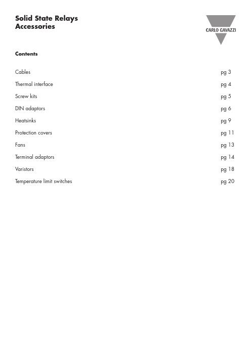
Solid State Relays Accessories, Screw Kits Types SRWKIT…
Ordering Key
Screw Kit Screw size Screw length
0.5 Nm -20° to + 70°C [-4 to +158°F] -40° to + 100°C [-40° to +212°F] DIN EN 50022, 50035
DIN Adaptor for 1-phase SSRs
DIN rail adaptor module for mounting the 1-phase SSR series RA, RD, RM, RS and RAM directly on DIN rail.
Type
UL style 2547 UL style 2464 UL style 2464 UL style 2464 UL style 2464 UL style 2464
Cable size
0.14mm2 0.14mm2 0.14mm2 0.25mm2 0.14mm2 0.14mm2
Termination
- Width x Height x Thickness = 35 x 43 x 0.25 mm
- Packing qty. 50 pcs.
RZHT
- Graphite thermal pad for RZ3 series with adhesive on one side
- Width x Height x Thickness = 70 x 77 x 0.25 mm
哈氏合金188热处理工艺哈氏合金188材料规格

合金188是一种钴基特殊合金,具有独特的高温强度和抗氧化性。
长期暴露在1400-1600 °f的温度范围内后,它仍然具有足够的延展性。
与镍基合金相比,钴基合金具有固有的高温蠕变性能。
在固溶强化过程中,向合金188中加入14% 钨,然后加入M6C和M23C6碳化物。
合金188易于加工,并且适用于手动和自动焊接。
焊接方法包括电子束、钨极氩弧焊和电阻焊。
a1a3a1a6a6a3a6a8a1a9a9188合金海恩斯1881.优异的高温强度和环保性188合金含有钴、镍、铬和钨,高温强度非常好。
如果长时间放置在1095 ℃的高温下,仍具有良好的抗氧化性,可有效抵抗含硫沉淀物的热腐蚀。
它可以用传统技术或铸造零件加工。
2.易于加工188合金具有良好的成形和加工特性。
它可以锻造或热处理。
热加工需要将工件在1175 ℃下保持足够长的时间温暖,以确保整个工件达到该温度。
由于该材料的延展性非常好,因此可以对188合金进行冷加工。
由于该合金具有快速冷硬化的特性,因此在加工复杂零件时,需要在两个过程之间进行多次退火。
冷热零件都需要退火处理和快速冷却,以恢复材料的性能。
该材料具有良好的有限焊接特性,可手动焊接或自动焊接,包括TIG、MIG、电子束焊接和电阻焊。
3.热处理锻造的188合金通常以固溶状态供应。
常规热处理方法为1175 ℃ +/-14 ℃固溶处理,然后快速冷却或水淬火以达到最佳性能。
在低于溶液温度的温度下,工艺退火会产生一些碳化物沉淀,这将影响188合金的性能。
4.各种供应形状188合金供应形状包括厚板、薄板、带材、块状、棒状、金属丝、管材5.应用广泛应用于航空工业、制造军用和商用气体发动机燃烧室、管道、后燃气部件等。
6.材料规格188合金满足以下材料规格:AMS5608 (片材、带材、厚板) AMS5772 (圆棒、锻造材料)188合金是一种固溶体强化材料,具有优异的高温强度和良好的室温加工性能。
它可以在650 ℃和更高的温度下长时间工作。
特种材料之哈氏合金介绍

哈氏合金(Hastelloyalloy)一、引言哈氏合金是镍基合金的一种,目前主要分为B、C、G三个系列,它主要用于铁基Cr-Ni或Cr-Ni-Mo不锈钢、非金属材料等无法使用的强腐蚀性介质场合,在国外已广泛应用于石油、化工、环保等诸多领域。
其牌号和典型使用场合如下表所示。
为改善哈氏合金的耐蚀性能和冷、热加工性能,哈氏合金先后进行了三次重大改进,其发展过程如下:B系列:B →B-2(00Ni70Mo28) →B-3C系列:C →C-276(00Cr16Mo16W4) →C-4(00Cr16Mo16) →C-22(00Cr22Mo13W3) →C-2000(00Cr20Mo16)G系列:G →G-3(00Cr22Ni48Mo7Cu)→G-30(00Cr30Ni48Mo7Cu)目前使用最广泛的是第二代材料N10665(B-2)、N10276(C-276)、N06022(C-22)、N06455(C-4)和N06985(G-3)。
第三代材料N10675(B-3)、N10629(B-4)、N06059(C-59)处于推广阶段。
由于冶金技术的进步,近年来出现了多个牌号的含~6%Mo的所谓“超级不锈钢”,替代了G系列合金,使得G系列合金的生产和使用迅速下降。
二、典型哈氏合金化学成分三、力学性能哈氏合金的力学性能非常突出,它具有高强度、高韧性的特点,所以在机加工方面有一定的难度,而且其应变硬化倾向极强,当变形率达到15%时,约为18-8不锈钢的两倍。
哈氏合金还存在中温敏化区,其敏化倾向随变形率的增加而增大。
当温度较高时,哈氏合金易吸收有害元素使它的力学性能和耐腐蚀性能下降。
材料的力学性能四、常用哈氏合金1:Hastelloy B-2alloy(哈氏B-2合金)一、耐蚀性能哈氏B-2合金是一种有极低含碳量和含硅量的Ni-Mo合金,它减少了在焊缝及热影响区碳化物和其他相的析出,从而确保即使在焊接状态下也有良好的耐蚀性能。
碳钢车削加工指南

过 0.05%。中碳钢有 16 个标准牌号,其切削参数 见表 3。
表 4 高碳钢的切削参数
工件 硬度 HB
切削1.0深0度 进0给.1率8 f 切削21速5 度
(0a.0p4)
(0.007) mm/r
(7V0c0)
刀C具P1材0 (C料P-7)
7m.5m0 ((英0.3寸0))
(0i.p5r0) m1/m05in CISPO3*0 (0.02) (s3f5m0) (A(CNCS-I6)*)*
切削参数
削参数
工件 硬度 HB
切削深度 ap mm
(英寸)
进给率 f mm/r (ipr)
切削速度 Vc
m/min (sfm)
刀具材料 ISO*
(ANSI)**
工件 硬度 HB
切削深度
切削速度 刀具材
进给率 f
ap
mm/r
Vc
料
mm
m/min ISO*
(ipr)
(英寸)
(sfm) (ANSI)**
7.50
在本例中,切削速度随着切深的减小而按相同比例增大[7.5÷5=1.5,170×1.5=255(原文为 0.300÷0.200=1.5,550×1.5=8
25sfm)。
2.
中碳钢
中碳钢(AISI 1029~1053)的含碳量为 0.25%~0.55%,含锰量为 0.30%~1.00%,含磷量不超过 0.04%,含硫量不超
0.50
170
CP30
7.50 0.50 160 CP30
(0.30) (0.02) (550) (CC-6)
(0.30) (0.02) (525) (CC-6)
85~125 3.80
马口铁介绍-GGC
• 外观:ETP有明亮的银白色金属光泽,TFS光 泽较暗;
• 耐蚀性:ETP的镀锡层能提供一定的耐腐蚀 性,但TFS的铬镀层极薄,基本不提供耐腐 蚀性,因此TFS不适合长期存放;
• 涂饰性:TFS表面与涂料的附着力优于ETP
• 焊接性:TFS没有自焊能力,因此不能用于 生产三片罐,只能生产顶底盖或两片罐。
• 连续退火:Continuous Anneal,简称CA; • 罩式退火:Batch Anneal,简称BA
CA
BA
材质稳定性好,能用于高速制罐 稳定性一般,只能用于中低速
线
制罐线
加工性能一般,有各向异性,不 延展性好,能用于比较复杂的 能用于变形、延展明显的罐形 罐形
机组投资较大,合同组织要求高,机组投资小,合同组织灵活,
H
7
六、ETP/TFS生产流程
炼钢 电镀
连铸 平整
热轧 退火
酸洗 冷轧
钝化
清洗
涂油
包装
H
8
七、ETP/TFS用途
• 制罐制盖等包装用途是最主要的用途,同时少量用于电子ห้องสมุดไป่ตู้类用途。
H
9
八、ETP/TFS分类
• 1,按标准分类 • 2,按轧制工艺分类 • 3,按牌号分类 • 4,按基板类型分类 • 5,按退火方式分类 • 6,按表面形态分类 • 7,按镀锡/铬量分类 • 8,按钝化方式分类 • 9,按切板方式分类 • 10,按卷形态分类
• L:用于生产盛装酸性内容物(桔子、黄桃、菠萝 等),且内面为素铁的食品罐的高耐蚀性镀锡板 基板钢种,此种镀锡板常称为K板;
• D:用于生产两片拉拔罐的高加工性镀锡板基板钢 种,此种镀锡板常称为DI材;