PC4VREFVCAPSCOM
网赢视讯VOPEX-USBH-2 4 DVI HDMI USB KVM 分频器使用说明书

Front and Rear View of VOPEX-USBH-2TRADEMARKVOPEX and the NTI logo are registered trademarks of Network Technologies Inc in the U.S. and other countries. All other brand names and trademarks or registered trademarks are the property of their respective owners.COPYRIGHTCopyright © 2004-2023 by Network Technologies Inc. All rights reserved. No part of this publication may be reproduced, stored in a retrieval system, or transmitted, in any form or by any means, electronic, mechanical, photocopying, recording, or otherwise, without the prior written consent of Network Technologies Inc, 1275 Danner Drive, Aurora, Ohio 44202.CHANGESThe material in this guide is for information only and is subject to change without notice. Network Technologies Inc reserves the right to make changes in the product design without reservation and without notification to its users.TABLE OF CONTENTS INTRODUCTION (1)LIMITATIONS (2)MATERIALS (2)CONNECTORS AND LEDS (2)INSTALLATION (3)Monitor Connection (3)Mouse Connection (3)Keyboard Connection (3)CPU Connection (4)Hub Ports (5)Power-Up (6)OPERATION (7)Keyboard Command Mode (7)Mice and Trackballs with MACs (8)International SUN Keyboards (8)Hub Ports (9)SPECIFICATIONS (9)TROUBLESHOOTING (9)WARRANTY INFORMATION (9)TABLE OF FIGURESFigure 1- Connect User 1 Keyboard, Mouse, and Monitor (3)Figure 2- Connect the VOPEX to the CPU (4)Figure 3- Example of configuration with HDMI extenders on input and output (5)Figure 4- Connect other devices to Hub Ports (5)Figure 5- Connect the AC adapter to the VOPEX (6)INTRODUCTIONThe VOPEX-USBH-2 (VOPEX) is a DVI/HDMI and USB KVM Splitter and 3-Port Hub. It enables the control of one USB enabled CPU through two separate USB keyboards, USB mice, and DVI or HDMI monitors and it enables the connection of 3 additional USB devices (other than keyboards or mice). Each user is able to have complete control of a CPU (although it is not recommended to access the CPU more than one at a time as unpredictable results may occur). While the user access is controlled by three (3) separate modes of operation, both user monitors will show the same image at all times. The 3 hub ports (for printer, scanner, camera, etc.) will be connected to the CPU at all times.Options:∙ A 4-port model (VOPEX-USBH-4) is available supporting up to 4 users.Types of User Input Devices Supported:∙USB keyboard with Windows layout∙USB keyboard with SUN layout∙USB keyboard with MAC layout∙USB Mouse - (up to 3 buttons)∙USB IntelliMouse (scroll wheel)∙Mouse-Trak trackball∙Logitech, Kensington and Microsoft Wheelmouse or Trackball on Mac CPUs with special drivers∙Logitech Cordless Elite Duo keyboard and mouse∙Crystal Vision keyboard with touchpad∙Gyration keyboard/mouse∙NTI USB-PS/2 Adapter∙NTI USB-SUN Adapter∙Logitech Comport MK345Types of Shared Devices Supported:∙Both low-speed and full speed USB devices are supported.∙USB 1.1 (low/full speed) standards.Video Support:∙Compliant with HDMI 1.2, HDCP 1.1 and DVI 1.0 standards. Plug-n-Play specification supported∙Supports HDMI CEC∙Supports HDTV resolutions up to 1080i and computer resolutions up to 1920x1200.Types of CPUs Supported:Any USB CPU supporting USB version 1.0 or above including:∙USB WINxx∙USB MAC∙USB SUNNTI Extenders Supported:∙ST-C6USBH-300 300 Foot HDMI USB KVM Extender∙ST-C6USBH-HDBT 328 Foot HDMI USB KVM Extender over HDBase-TLIMITATIONS∙The USB ports on the VOPEX are USB 1.1 compatible. Any USB 2.0 device connected to the VOPEX will be regulated to USB 1.1 speeds.MATERIALSMaterials included with this kit:∙VOPEX-USBH-2/4 2/4-Port DVI/HDMI USB KVM Splitter∙USB2-AB-1M-5T 1 Meter Transparent USB A-B Device Cable∙DVI-HD-3-MM 3' M-M DVI-to-HDMI Video Cable∙120 or 240VAC @ 50 or 60Hz-5VDC/3.0A AC Adapter (2-Port Model)or∙120 or 240VAC @ 50 or 60Hz-5VDC/6.0A AC Adapter (4-Port Model)∙URL Slip with path to this manualCONNECTORS AND LEDSLABEL CONNECTOR/LED DESCRIPTIONO Power Switch To power up or power down the VOPEX1 I/2 Power Green LED Illuminates to indicate proper power to the unitx Green LED For visual indication of the splitter’s operating mode3 UserSelect Push Button Press to manually switch between operating modes4 ModeIN HDMI Type A female for connecting the video cable from the CPU5 VIDEOx HDMI Type A female for connection of the user video monitors6 MONITOR3.0A 2.1x5.5mm Power Jack for connection of power supply7 5VDCPORTS USB type A female for connection of the cables from USB devices8 HUB9 USER x DEVICES USB type A female for connection of user USB device(s) (keyboard and mouse)10 CPU USB type B female for connection of the devices cable from the CPUINSTALLATIONFYI: It is not necessary to disconnect power to the CPU and monitor(s) before installation.Monitor Connection1.Disconnect the monitor cable at the CPU and reconnect it to the "MONITOR 1" port on the VOPEX. (See Fig. 1)(A second DVI-HDMI-x-MM cable may be required (sold separately)- one has been supplied for connection to the CPU.)2.Plug a second monitor into the "MONITOR 2" port on the VOPEX.Mouse Connection1. Disconnect the mouse at the CPU and reconnect it to one of the female USB type A 'USER 1 DEVICES" ports on theVOPEX.2. Connect a second mouse (or optional USB extension cable NTI USB-A+A-5M) to the female USB type A "USER 2 DEVICES"ports on the VOPEX.Keyboard Connection1. Disconnect the keyboard at the CPU and reconnect the keyboard to the remaining female USB type A "USER 1 DEVICES"port on the VOPEX.2.Connect a second keyboard (or optional USB extension cable NTI USB-A+A-5M) to the remaining female USB type A "USER2 DEVICES" ports on the VOPEX.Figure 1- Connect User 1 Keyboard, Mouse, and MonitorCPU Connection1. Connect the male USB type A connector end of the USB2-AB-1M-5T cable into the device port on the CPU.2. Connect the male USB type B connector of the same cable to the "CPU" port on the VOPEX.3.Connect the male DVI-D connector end of the DVI-HD-3-MM into the CPU’s video port. (See Fig. 2)4.Connect the male HDMI connector end of the DVI-HD-3-MM into the "VIDEO" port on the VOPEX.Figure 2- Connect the VOPEX to the CPUNote: If your CPU has an HDMI video port instead of DVI, an HD-xx-MM cable can be purchased separately from NTI. Contact your NTI salesperson or visit our web site at for details.Figure 3- Example of configuration with HDMI extenders on input and outputHub PortsIf desired, connect additional USB devices toeach of the three "Hub Ports". These portswill be powered and operational anytime the VOPEXand CPU are powered ON. See Fig. 3.Figure 4- Connect other devices to Hub PortsPower-UpConnect the AC adapter to the VOPEX and power ON the VOPEX. If not already ON, power ON the CPU and monitors.Figure 5- Connect the AC adapter to the VOPEXOPERATIONMode SelectionThe VOPEX comes equipped with three (3) modes of operation- INSTANT AUTO, DELAYED AUTO, and USERx. To manually toggle between modes, depress the MODE button once each time a mode change is desired. Select the mode according to the chart below.INSTANTANEOUSAll users have control of the CPU simultaneously.DELAYThe first user with an activedevice gets control of CPU. The second user is locked out until after 5 seconds of inactivity from the first user.USER 1"USER 1" has sole access. Other users are locked out.USER 2 "USER 2" has sole access. Other users are locked out.USER 3 "USER 3" has sole access. Other users are locked out. ------USER 4"USER 4" has sole access. Other users are locked out.------Note: In Instantaneous Mode all users have control of the CPU simultaneously, but it is recommended that only one user take control at a time. Movements from multiple mice at the same time will cause unpredictable movements on the monitor.Keyboard Command ModeIn order to control the other features of the VOPEX with the keyboard, Command Mode must be enabled. To enter Command Mode from the keyboard:PressWhen the Command Mode is enabled, all 3 status lights on the keyboard will illuminate and both LED’s on the VOPEX will blink continuously to indicate Command Mode is enabled. See the table below for functions that are available while in Command Mode.NOTE: The user must exit Command Mode in order for the CPU to switch to the selected mode. To exit Command Mode, press ESC on the keyboard. The mouse will not operate while in Command Mode.NOTE: While in Command Mode, when a proper programming command is entered and is recognized by the switch, the hiLED’s on the keyboard will flash once to indicate acceptance. The user must exit Command Mode (by pressing ESC) to see a change take effect in the switch operation .NOTE: The VOPEX will automatically exit Command Mode after 5 seconds of inactivity by the user if the user does not manually exit Command Mode.+Ctrl ~(ACCENT KEY)`U1U2U3U4U1U2U1U2U3U4U1U2U1U2U1U2U3U4U1U2U3U4U1U2U1U2U3U4U1U2U3U4The following functions exist while in Command Mode:<X>-<key>-<Y> Select a new key sequence to use to enter Command Mode – Replace <key> with the desired keyto follow <Ctrl> with. Note: <Ctrl> + <'> will still function as a method to enter Command Mode<L> - <x> - <x> Select the country code of the keyboard being used with a USB SUN CPU (see Country Codeschart below)<V> - <Enter> This will print the version of the code in the VOPEX to a text editor window (i.e. Windows Notepad)for use when troubleshooting the VOPEX. Note: The text editor should be open and active prior toentering Command Mode.<M> Configure the CPU port to connect to a MAC CPU (see "Mice and Trackballs with MACs" below.)<W> Configure the CPU port to connect to a Windows or SUN CPU<D> - <x> Select the operating mode, x=1 for Instantaneous Mode, x=2 for Delay Mode, x=3 User 1Mode, x=4for User 2 mode. x= 5 for User 3 Mode, x=6 for User 4 Mode. (Modes are described in the table onpage 6.)<P> - <x> Select the default mode to have the VOPEX enter upon power-up.<Esc> Exit Command ModeMice and Trackballs with MACsThe VOPEX can be configured to enable full functionality between mice and trackballs having two or more buttons and a USB MAC CPU. By default, the CPU port on the VOPEX is configured for use with a WINDOWS or SUN CPU and has no special translation for using multi-function mice and trackballs when a MAC CPU is connected. Using the commands in Command Mode above, either enable or disable this feature as needed.NOTE: Be sure to re-configure the port for connection to a WINDOWS or SUN CPU if a MAC CPU is removed and a WINDOWS or SUN CPU is then connected.International SUN KeyboardsThe VOPEX can recognize international layouts for Sun keyboards. To use an international Sun keyboard, follow this procedure:1. Disconnect the CPU from the VOPEX2. Connect the international keyboard to be used to the VOPEX3. Power down the VOPEX for at least 3 seconds4. Power up the VOPEX5. Reconnect the CPU to the VOPEXIt is also possible to configure the VOPEX to emulate a specific international Sun keyboard regardless of what actual keyboard is connected. This is recommended when the CPU needs the layout code (i.e. a SUN CPU) and the keyboard doesn't have an explicit layout code (i.e. some Windows keyboards). To do this, manually set the VOPEX to indicate the international keyboard identification number to the CPU using the following procedure:1. Connect the keyboard to be used to the VOPEX2. Power down the VOPEX for at least 3 seconds3. Power up the VOPEX4. Enter Command Mode (<Ctrl> + <`>)5. Type Lxx, where xx is the number from the list below that corresponds to the desired country code6. Exit Command Mode7. Power down the VOPEX for at least 3 seconds8. Power up the VOPEX9. Reboot the CPU connected to the VOPEXCountry CodesNetherlands/Dutch 27 Swiss/French Supported 09 German 1800 NotNorwegian 28 Swiss/German 01 Arabic 10 Greek 19(Farsi) 29 Switzerland02 Belgian 11 Hebrew 20PersianPoland 30 Taiwan03 Canadian-Bilingual 12 Hungary 2104 Canadian-French 13 International (ISO) 22 Portuguese 31 TurkishRussia 32 UK Republic 14 Italian 2305 CzechSlovakia 33 US06 Danish 15 Japan(Katakana) 24Spanish 34 Yugoslavia07 Finnish 16 Korean 25Swedish 35-99 Reserved08 French 17 LatinAmerican 26Hub PortsThe three connections labeled "Hub Ports" can be used to connect any USB device, such as a printer, scanner, camera, etc. for continuous operation at USB 1.1 compliant speeds. These ports are not controlled by the VOPEX.SPECIFICATIONSSize: Each unit is 8.5”W x 6”D x 2.6”HPower: VOPEX-USBH-2- Powered by 120 or 240VAC @ 50 or 60Hz-5VDC/3.0A AC AdapterVOPEX-USBH-4- Powered by 120 or 240VAC @ 50 or 60Hz-5VDC/6.0A AC AdapterConnections: HDMI Type A- supports HDTV resolutions to 1080i and computer resolutions to 1920x1200. VGA & SGAcompatibleUSB Type A female device connectorsUSB Type B female CPU connectorTROUBLESHOOTINGPROBLEM SOLUTION∙Keyboard error ∙Check cable connections on CPU and VOPEX∙Mouse not working ∙Check cable connections on CPU and VOPEXWARRANTY INFORMATIONThe warranty period on this product (parts and labor) is two (2) years from the date of purchase. Please contact Network Technologies Inc at (800) 742-8324 (800-RGB-TECH) or (330) 562-7070 or visit our website at for information regarding repairs and/or returns. A return authorization number is required for all repairs/returns.Man123 Rev 1/17/23。
芝麻坊 4 系列电脑电源说明书
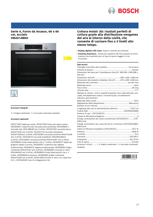
Serie 4, Forno da incasso, 60 x 60cm, AcciaioHBA514BR0Accessori integrati1 x Griglia combinata, 1 x Leccarda universale smaltataAccessori opzionaliHEZ317000 Teglia per pizza, HEZ327000 Pietra per pane e pizza, HEZ333001 Coperchio per leccarda extra profonda, HEZ530000 2 leccarde slim 455x188x39 mm (LxPxA), HEZ531000 Leccarda bassa 455x375x30 mm (LxPxA), HEZ531010 Leccarda antiaderen455x375x30mm (LxPxA), HEZ532000 Leccarda profonda 455x375x38 mm (LxPxA), HEZ532010 Leccarda antiaderen 455x400x38mm (LxPxA), HEZ533000 Leccarda profonda 455x375x81 mm (LxPxA), HEZ538000 Guide telescopiche clip a 1 livello, HEZ629070 Teglia per grigliare adatta a pirolisi, HEZ633001 Coperchio per tegame professionale, HEZ633070 Tegame professionale, HEZ634000 Griglia combinata 455x375x31 mm (LxPxA), HEZ636000 Leccarda in vetro 455x364x30 mm (LxPxA), HEZ638000 Guide telescopiche clip a 1 livello, HEZ660050 Accessory, HEZ664000 Griglia combinata455x375x59 mm (LxPxA), HEZ915003 Pirofila in vetro con coperchio 5,4 l., HEZG0AS00 Cavo di collegamento 3m Cottura HotAir 3D: risultati perfetti di cottura grazie alla distribuzione omogenea del aria al interno della cavità, che consente di cucinare fino a 3 livelli allo stesso tempo.• Display digitale LED rosso: facile e comodo da utilizzare.• Cleaning Assistance: pulizia più semplice del forno grazie al nuovo sistema che è perfetto per un tipo di sporco leggero e non incrostato.Dati tecniciTipologia costruttiva del prodotto: .....................................Da incasso Sistema di pulizia: ....................................................................Idrolisi Dimensioni del vano per l'installazione (AxLxP): 585-595 x 560-568 x 550 mmDimensioni (AxLxP): ............................................595 x 594 x 548 mm Dimensioni del prodotto imballato (AxLxP): .......675 x 690 x 660 mm Materiale del cruscotto: ...................................................acciaio inox Materiale porta: ..........................................................................vetro Peso netto: ..............................................................................29.3 kg Volume utile: .................................................................................71 l Metodo di cottura: .Grill a superficie grande, Aria calda delicata, aria calda, Riscaldamento statico, Funzione pizza, riscaldamento inferiore, grill ventilatoMateriale della cavità: .................................................................Altro Regolazione della temperatura: ..........................................Meccanico Numero di luci interne: (1)Lunghezza del cavo di alimentazione elettrica: .....................120.0 cm Codice EAN: (4242005033683)Numero di vani - (2010/30/CE): (1)Classe di efficienza energetica: .........................................................A Energy consumption per cycle conventional (2010/30/EC): ........0.97 kWh/cycleEnergy consumption per cycle forced air convection (2010/30/EC):0.81 kWh/cycleIndice di efficienza energetica (2010/30/CE): ..........................95.3 % Potenza: ..................................................................................3400 W Corrente: .....................................................................................16 A Tensione: .............................................................................220-240 V Frequenza: ...........................................................................60; 50 Hz Tipo di spina: ..........................................................................Schuko Accessori inclusi: .......1 x Griglia combinata, 1 x Leccarda universale smaltataSerie 4, Forno da incasso, 60 x 60cm, AcciaioHBA514BR0Cottura HotAir 3D: risultati perfetti di cottura grazie alla distribuzione omogenea del aria al interno della cavità, che consente di cucinare fino a 3 livelli allo stesso tempo.Caratteristiche principali- 7 programmi di cottura: MultiCottura HotAir 3D, Riscaldamento superiore e inferiore, Grill ventilato, Grill a superficie grande, Funzione pizza, Riscaldamento inferiore- Display digitale LED rosso- Volume cavità: 71 l- Regolazione della temperatura da 50 °C a 275 °C- Cleaning AssistanceAltre caratteristiche- Riscaldamento rapido- Orologio elettronico con impostazione inizio e fine cottura- Illuminazione interna alogenaAccessori- Accessori: 1 griglia combinata, 1 leccarda universale profonda smaltataEtichetta energetica- Assorbimento massimo elettrico: 3.4 kW- Classe di efficienza energetica (acc. EU Nr. 65/2014): A(in una scala di classi di efficienza energetica da A+++ a D)- Consumo energetico per ciclo durante funzionamento convenzionale:0.97 kWh- Consumo energetico per ciclo durante funzionamento ventilato:0.81 kWh- Numero di cavità: 1 Tipo di alimentazione: elettrica Volume della cavità:71 lSerie 4, Forno da incasso, 60 x 60cm, Acciaio HBA514BR0。
霍尔比格阀门维护指南说明书

COMPRESSIONTECHNOLOGYGROUPService GuideSERVICE GUIDE FOR MAINTENANCE OF HOERBIGER VAL VESGeneralSERVICE GUIDEFOR MAINTENANCE OF HOERBIGER-VAL VESASSEMBLY DEVICEThe HOERBIGER Assembly Device allows the valve to be held correctly without danger of damage. Adjustable location pins secure the valve against rotation.These pins locate in the slots of the seat or guard respectively without causing damage. The best way to tighten the nut is with a torque wrench.HOERBIGER AssemblyDevices can be used for all valve types. The standard clamps will hold heights "H" (fig. 12) up to 78 mm. The base plate can be screwed on to any work bench or held in a suitable holding device.Modern compressors equipped with HOERBIGER-Valves require a minimum of maintenance. The performance and the reliability of such compressors depend,however, to a large degree on the care applied to these few maintenance operations.AT WHAT INTERVALS HAS MAINTENANCE OF VALVES TO BE CARRIED OUT?We cannot give any general guide lines as valve life is influenced by manyparameters. Maintenance frequency will depend for example on the type of compressor (e.g. Process machine or garagecompressor), whether the compressor is running on continuous duty orintermittent duty, on the compressor speed andpressures, the compression ratio, also the type of gas (corrosive or non-corrosive gas, clean gas with or without carry-over of foreign material,moisture content). Thecompressor manufacturer will have established guide lines both for the running in period and subsequent operation,which will have to befollowed. Experience proves that after the initial running -in period the maintenance intervals can be extended considerably.THEY COVER THE FOLLOWING PROCEDURES1Remove valve from compressor 2Dismantle the valve 3Clean all parts4Check the condition of all componentsespecially for wear, damage to the seat face, the plates, and for setting of the springs.5Repair or replace worn partsRepair all parts which can be remachined without impairing the strength. Replace all parts which are worn or show any cracks.6Reassemble the valve following the instructions on our drawing or assembly sheet.RECOMMENDATIONS AND WARNINGS1Recommendations and warnings are to be followed according to the compressor manufacturer.In case our recommendations and warnings deviate from those of the compressormanufacturer, the ones of the compressor manufacturer take precedence.3 sizes are available:Sizemax. O. D.L B of valve mm mm mm 120-100260120220-250420200320-430590350fig. 1fig. 3fig. 4fig. 2fig. 5dismantlefig. 6fig. 7fig. 8fig. 91Remove valve from compressor2Before valves are removed from thecompressor, all pressure has to be released from the cylinders and piping. If combustible or poisonous gases are present, cylinder and piping have to be vented.Take necessary measures to prevent start up of thecompressor. If the compressor valve is stuck in the cylinder,try to use valve puller device.If valve is to be jarred free by striking, use a wood block or soft metal bar to avoid damage. Never use a steel hammer to strike the valve directly.2Dismantle the valveAfter sufficient cleaning of the center bolt and loosening of the locking device of the unit (either by removing of the cotter pin in case of a castle nut, or by pressing down the ends of the locking washer, if equipped with same), thevalve should be held by means of a simple holding device shown in fig. 3 and 4. The holding pins keep the valve from rotating. It is better to use our Standard Assembly fixture shown in fig. 1 and 2where the valve parts are clamped down effectively.3In order to prevent the locating pins in the valve from shearing off, it is advisable to hold the suction seat and delivery guard respectively,while loosening or tightening the nut especially in the case of valves with open guard (fig. 5).4How it should not be done!Never should a valve be directly tightened in a vice,neither as shown in fig. 6 on the shoulder, nor as shown in fig. 7. Do not hammer on the wrench when loosening ortightening the nut (fig. 8 and 9).check repairfig. 10fig. 11.2fig. 11.13Clean all partswith a cleansing fluid using a soft brush, taking particular care to free the ports of the seat and the guard from all foreign matter to ensure full seat area in operation. Never use wire brushes or tools with sharp edges to clean the seats and plates.5All precautionary measures stipulated by the Occupational Safety and Health Act of 1970 (OSHA)or local safety instructions must be adhered to when handling solvents.Caution: all excess solvent solutions used in the cleaning of compressor valves and/or pockets should be removed prior to start-up since their presence may cause an explosion hazard.4Check the condition of all components6Use only genuineHOERBIGER replacement parts.5Repair or replace worn partsValve platesWhen a valve plate, or damper plate shows signs of wear, it is imperative to replace these parts, even if no breakage has occurred.7Valve plates and rings when worn should be replaced, not reground or inverted.8When a spring in a valve shows signs of deterioration,not only that particular spring but all springs must bereplaced in this valve. In the case of conical springs care should be taken that they are inserted into the spring well with the large diameter resting at the bottom of the spring well (fig. 10).SeatsFor highest efficiency of the valve it is important that the seat face is flat and free of any traces of wear, thuspreventing valve leakage. If any damage of the seat face appears, it is necessary to remachine and lap the seating areas. Locating pins, if fitted,have to be removed first of all.Generally remachining is done by concentric grinding and lapping. If the seat face shows only slight defects,lapping alone may provesatisfactory. Also remachining on a center lathe with very low feed may be considered,particular attention being paid to the seat face being machined. Burrs are best removed with emery paper (fig. 11.1 and 11.2)9When a valve seat surface is remachined, new valve plates or rings must be used to assure proper seal.How often may a valve seat be remachined?Under no circumstances must the bottom of the turned slots be machined to increase the depth, as this would impair the strength of the seat. The following may serve as a rough guide for remachining of seats. The materialthickness …e“ (fig. 11.1) under the seating ledge should not be reduced to less than 60%of the slot width …b“ anexeption to the above are the steel seats of valve Types 52 R and 42 R, for whichdimension …e“ should be limited to 1.2 mm minimum.Every grinding or lapping of the seat face increases the width of the ring surface marked …I“ in fig. 11.2. In order to keep the dimension constant the grooves have to be remachined. The maximum increase on width which canbe tolerated is 20%.hole for drivingremachining of seat-faceremachining of groovefig. 13fig. 12fig. 14fig. 15X… free length before and after remachiningY… height reduction by remachiningfig. 1610 Do not remachine valve seats below the specified minimum dimension,otherwise there is danger of breakage.11Remachining has to be extended over the entire seat-face, including the center where lift washers or guide rings are located, in order to avoid any change of the valve lift.Center bolts are secured into seats (or guards) with a dowel pin (Version A) or a bolt lock using a small ball (Version B). To remove the centre bolt, drill out the (soft)dowel pin or ball andunscrew the bolt. Upon re-assembly drill a new hole in the thread area of theThe dowel pin or ball, after it is inserted, has to be peened (slightly hammered in) to prevent it from falling out (fig. 13).If so-called safety guards (Standard design fig.16) are centered on the seat, care must be taken to maintain dimension …H“ (fig. 16). This means any centering step on the seat, must be remachined to the same extent as the seat face.After remachining of the seat the locating pins have to be refitted (fig. 15).12If the valve plate and guide plate are riveted together, the groove in the valve seat under the rivets has to be remachined after every grinding to prevent the rivet heads from hitting the seat.Remachine until the rivet hasample clearance (fig. 14).Certain valves have no hole in their seat to accept the free end of the locating pin. Such valves are provided with marking holes on theperiphery of seat and guard or visually by aligning the webs of the seat and guard, which must be lined up before the valve nut is tightened down (see fig. 16).bolt and the seat or guard,respectively, and insert a new pin or ball to secure the bolt from coming loose.The diameter of the new hole has to provide a press fit (dia.of drill. 0.1 mm less than dia.of locating pin). Make sure that the locating pins are at right angles to the seat face.When re-assembling the valve align the seat with the guard. In this position the nut can be tightened. Never tighten the nut without positioning the seat andguard properly. Any damage of the locating pins canimpair the proper functioning of the valve.Valves using spirol pins instead of solid dowel pins must never have through holes in the seats to accommodate the pin.Drilling a through hole would result in leakage through thevalve seat.Version BVersion A Where possible we provide a small recess around the center bolt to facilitate regrinding of the seat face without removing the Centerboltwhen remachining seat-face provide clearancefor the rivetsthese holes must be alignedLocating PinsLocating pins, which have been removed from the seat before the remachining, have to be refitted, taking care that the free length is the same as before (fig. 15). If necessary,the pin holes have to be drilled deeper in order to ensure that the maximum free length is not exceeded. If the pin in the seat or the hole is damaged redrill thelocating pin holes displaced by 180°.fig. 17fig. 186Reassemble the valveTake special care inassembling the valve and follow procedures shown on our drawings. We are glad to give any further advice should problems arise. If valves are equipped with lock washers or locking plates, they have to be replaced after every dismantling. For more convenient assembly of the valve it is a good practice to grease the spring pockets, in order to hold the springs in place. This does not apply for valves of oxygen compressors.You will do a better job if you use a torque wrench fortightening the selflocking nut.(Follow the torque table given in this leaflet). Whentightening the nut hold the suction seat, or the discharge guard, especially in case of valves with open guards (fig.5) both parts should not move relative to each other. This could damage the locating pins in the valve and result in valve failure. Certain valves are provided with marking holes on the periphery of seat and guard which must be lined up before the valve nut is tightened down (fig. 16).13 Never use oil orgrease for valves used on oxygen-compressors!14Tightening torque ofcenter bolt nut has to be maintained as specified. Bolt and nut threads must be clean,free of burrs and welllubricated. CAUTION: With Oxygen Compressors. Valves have to be completely free of oil and grease. Inspect valve again before installation.Failure to do so many result in an EXPLOSION!Never use self locking nuts on austenitic stainless steel material.The torques listed in the table are for greased nuts and bolts.The data is only valid with a Genuine Centre Bolt. Self locking nuts should always be lubricated before tightening.15 If suction valves are equipped with unloaders, the clearance between the valve plate and unloader finger as well as the clearance between unloader and actuator push rod has to be checked.16 Valve plates have to be checked for free movement.17 Before assembling the valve into the cylinder also clean the valve pocket and the cages.18 When re-installing valves, do not interchange suction and discharge valves -DANGER OF EXPLOSION!19 Do not installdischarge valves upside down - DANGER OF EXPLOSION!20Valves must always be placed in the cylinder with the center bolt and nut AWAY from the cylinder bore.21Set screws or cover stud nuts holding the valve in place have to be tightened to the specified torque values,otherwise there is danger of valve seat breakage.22After all of the valves are installed, bar over the compressor at least one complete revolution to be certain there is no interference with moving parts.Table of torque.(valid for castle nuts, slotted nutsand self locking nuts).PRACTICAL LEAKAGE TESTINGOF COMPRESSOR VAL VEStesting*) Martensitic stainless steel (magnetic) is used with slightly corrosive gases**) Austenitic stainless steel (non magnetic) is used with highly corrosive gasesfig. 20Compressor valves should be flowefficient and durable in service. Leakage is one criteria that impacts on both of the above. Excessive leakage causes back-flow of gas when the valve is closed, raises the temperature of the gas and reduces efficiency. Elevated temperatures also adversely affect valve life.For this reason, HOERBIGER`s quality assurance program dictates that all valves are subjected to a leakage test. This policy covers newly made valves in our production plants and repaired valves in all our service centers. Different geometry valves and sealing elements made from steel or non-metallic material all undergo such rigorous testing.Test methods may vary butpreference is given to thoseprocedures that simulate theconditions as they exist in acylinder.VALVE TESTINGMETHODSThere are 3 customary leakagetest procedures, andHOERBIGER recommends 2of the testing methods.Flow Meter TestingThe leakage is determined bysubjecting the closed valve toa "set" air pressure of e.g. 5bar (70 PSI) and measuringthe leakage through the valveby means of a flow meter (fig.19).Since small contaminants attimes can be caught betweenthe valve plate and seat lands,it is common practice to"tap" the valve plate in severalareas repeatedly. This willbriefly lift the plate off theseat lands and the escaping airwill blow out any smallparticles that might betrapped between the sealingsurfaces and cause excessiveleakage.This should be done with anappropriate tool (flat or soft-tipped) so no damage is doneto the valve plate or sealingelement. Particular care iscalled for when non-metallicplates are used so no damageis done to these components.Measuring Pressure DropIn this test method, leakage ismeasured in pressure dropover time, using a fixedvolume "V" (air supply is shutoff) and measuring the time ittakes for the pressure to dropfrom p1 to p2 (fig. 20).The time for the pressuredrop to occur and parameterfor acceptable leakage aredependent on the valve size,volume of the vessel and theselected pressures of p1 andp2.The prior "tapping" of thevalve to blow out anyimpurities should be standardpractice in this test procedureas well.Liquid TestingTest procedures as discussedunder 2.1 and 2.2 arecompatible and representconditions as they prevail inthe compressor cylinder. Thesealing element is "pressureloaded" much like it is in itsoperating environment wheninstalled in a cylinder (thesuction valve is kept closed bythe cylinder pressure whilethe discharge valve is underthe influence of the linepressure).TestOur experts are available at any time -worldwidetestingHOERBIGER CORPORATION OF AMERICA INC.• 3350 Gateway Drive • USA-FL 33069 Pompano Beach, Florida Phone+1+954947-5700•Fax+1+954974-0964•****************************•WebsiteFrequently, field people do not have access to leakage testers and resort to a simple "liquid testing" of the valve.Filling the seat ports of a valve with a fluid and observing the leakage rate of the fluid through the valve is acommon practice. Kerosene,Varsol and other lightviscosity fluids (even water)are employed in such crude leakage tests.Although the procedure is widely used, it is not without controversy as to the viability of its results. Contrary to the previously described methods of air pressure testing, the liquid test does not simulate conditions as found in the cylinder. The fluid pre-loads the sealing element towards its opening lift, and test results can be distorted,especially if valves use non-metallic sealing elements andCertain valves, due to thier design, cannot be tested at all with the fluid method, and others will create theappearance of "leakers" when their sealing characteristic under air pressure is perfectly acceptable. This test method,therefore, is controversial and should be avoided whenever possible. The cleaning process described in air testing cannot be applied in liquid tests, and any impurities in the sealing area will show as excessive leakage.Frequently, such liquid tests lead to unnecessary labor and repair of the valve whichwould possibly be termed fine under air tests.It is recognized that proper testing of valves with air pressure is not alwayspossible, but it remains the superior prodedure and should be adopted wherever possible.A6V651A01BAA05XU.S. Service Centers Gulf Coast Region 5405 Consulate Plaza Dr.Houston, Texas 77032Telephone 281-442-2497Toll-Free 800-888-8803Fax 281-442-5926FM624, County Road 73Robstown, Texas 78380Telephone 361-387-0545Toll-Free 800-873-2165Fax 361-387-804912020 Lakeland Park Blvd., #133Baton Rouge, Louisiana 70809Telephone 225-751-3909Toll-Free 800-888-5458Fax 225-751-6417Mid-continent Region 2029 South HarvardOklahoma City, Oklahoma 73128Telephone 405-681-3100Toll-Free 800-678-6118Fax 405-681-65193900 S. County Road 1290Odessa, Texas 79765Telephone 915-563-0150Toll-Free 800-999-6957Fax 915-563-01801227 Market Road Longview, Texas 75604Telephone 903-297-9207Telephone 903-297-9208Fax 903-297-92162805 Inland StreetFarmington, New Mexico 87401Telephone 505-324-9410Fax 505-324-9412Northeast Region 77 McCullough Drive, Bay #2New Castle, Delaware 19720Telephone 302-332-5090Fax 302-332-5680163 East Street Charles Road Carol Stream, Illinois 60188Telephone 630-653-7018Fax 630-653-7299Western Region25057 Anza DriveSanta Clarita, California 91355Telephone 661-257-2888Toll Free (in California) 800-321-3163Fax 661-257-1823Hoerbiger (Canada) LTD.330 Brunel RoadMississauga, Ontario L4Z 2C2Telephone 905-568-3013Fax 905-568-2407Bay 7 - 2616 - 16 Street N.E.Calgary, Alberta T2E 7J8Telephone 403-291-3822Fax 403-250-3426#108 10919 96th Avenue Grande Prairie, Alberta T8V 3J4Telephone 403-5332-1365Fax 403-539-493110907 91st AvenueFort St. John, British Columbia V1J 6G7Telephone 250-785-4602Fax 250-785-4604Hoerbiger de Mexico S.A. de C.V.Av. Calzada de la Naranja 166Fracc. Ind. Alce Blanco Naucalpan, Edo. Mex. C.P. 53370MexicoTelephone 52 5 576 6725Fax 52 5 359 2599Hoerbiger - Tecnival S.A.Centro Industrial Laper Primera Calle La Industria Palo Verde, Caracas, 1070-AVenezuelaTelephone 58 2 251 395158 2 251 376758 2 251 0806Fax 58 2 251 1777Hoerbiger de Argentina S.A.Peru 1011 (1602)Buenos Aires ArgentinaTelephone 54-11-47600014Fax 54-11-47301425J.J. Lastra 1550/56Q8302AAT NeuquenArgentinaTelephone +54-299-448-1945Fax +54-299-448-1945Hoerbiger do Brazil Rua Osasco, 102007750-000 Cajamar -SP Parque Empresarial Anhanguera Rod. Anhanguera, Km 33Sao Paulo, Brazil。
摩诺 V2406C 系列铁路计算机说明书

V2406C SeriesIntel®7th Gen Core™CPU railway computer with power isolation,2mini PCIe expansion slots for wireless,and2hot-swappable HDD/SSD slotsFeatures and Benefits•Intel®Celeron®/Intel®Core™i3/i5/i7high performance network videorecorder for rolling stock applications•Two hot-swappable2.5-inch HDD or SSD storage expansion trays•API library for easy deployment and storage volume notification•4K resolution HDMI display•2Gigabit Ethernet ports with M12X-coded connectors•M12A-coded power connector•Complies with all EN50155mandatory test items1•Compliant with EN50121-4•IEC61373certified for shock and vibration resistance•-40to70°C wide-temperature models availableCertificationsIntroductionThe V2406C Series embedded computers are based on the Intel®7th generation processor and feature4RS-232/422/485serial ports,dual LAN ports,and4USB3.0hosts.In addition,the V2406C computers provide1VGA output and1HDMI display with4K resolution support.The computers comply with the EN50155:2017specifications,covering operating temperature,power input voltage,surge,ESD,and vibration,making them suitable for a variety of industrial applications.The mSATA socket,SATA connectors,and USB sockets provide the V2406C computers with the reliability needed for industrial applications,which require data buffering and storage expansion.Most importantly,the V2406C computers come with2hot-swappable storage trays for inserting additional storage media,such as hard disk or solid-state drives,and support hot swapping for convenient,fast,and easy storage replacement. Each storage tray has its own LED to indicate whether or not a storage module is plugged in.1.This product is suitable for rolling stock railway applications,as defined by the EN50155standard.For a more detailed statement,click here:/doc/specs/EN_50155_Compliance.pdfAppearanceFront ViewRear ViewSpecificationsComputerCPU V2406C-KL1-T:Intel®Celeron®3965U processor(2M Cache,2.2GHz)V2406C-KL3-T:Intel®Core™i3-7100U processor(3M Cache,2.4GHz)V2406C-KL5-T:Intel®Core™i5-7300U processor(3M Cache,2.6GHz)V2406C-KL7-T:Intel®Core™i7-7600U processor(4M Cache,2.8GHz) Storage Slot 2.5-inch HDD/SSD slots x2mSATA slots x1,internal mini-PCIe socketSupported OS Linux Debian9Windows10Embedded IoT Ent2019LTSC64-bit System Memory Slot SODIMM DDR4slot x2DRAM32GB maxGraphics Controller Intel®HD Graphics620Computer InterfaceEthernet Ports Auto-sensing10/100/1000Mbps ports(M12X-coded)x2 Digital Output DOs x2Serial Ports RS-232/422/485ports x4,software selectable(DB9male) Digital Input DIs x6USB3.0USB3.0hosts x4,type-A connectorsAudio Input/Output Line in x1,Line out x1,3.5mm phone jackVideo Output VGA x1,15-pin D-sub connector(female)HDMI x1,HDMI connector(type A)Digital InputsConnector Screw-fastened Euroblock terminalI/O Mode DIIsolation3k VDCSensor Type Wet contact(NPN or PNP)Dry contactDry Contact Logic0:Short to GNDLogic"1":OpenWet Contact(DI to COM)Logic"1":10to30VDCLogic"0":00to3VDCDigital OutputsConnector Screw-fastened Euroblock terminal10-pin terminal blockCurrent Rating200mA per channelI/O Type SinkVoltage24to30VDCIsolation3kVDCLED IndicatorsSystem Power x1Storage x1LAN2per port(10/100/1000Mbps)Serial2per port(Tx,Rx)Serial InterfaceBaudrate50bps to921.6kbpsData Bits5,6,7,8Flow Control RTS/CTS,XON/XOFF,ADDC®(automatic data direction control)for RS-485,RTSToggle(RS-232only)Parity None,Even,Odd,Space,MarkStop Bits1,1.5,2Serial SignalsRS-232TxD,RxD,RTS,CTS,DTR,DSR,DCD,GNDRS-422Tx+,Tx-,Rx+,Rx-,GNDRS-485-2w Data+,Data-,GNDRS-485-4w Tx+,Tx-,Rx+,Rx-,GNDPower ParametersInput Voltage24to110VDCPower Connector M12A-coded male connectorPhysical CharacteristicsHousing AluminumDimensions(without ears)250x75x150mm(9.84x2.95x5.91in)Weight2,700g(5.95lb)Installation Wall mounting(standard)Protection PCB conformal coatingV2406C PCB conformal coating:Available on requestEnvironmental LimitsOperating Temperature-40to70°C(-40to158°F)Wide Temp.Models:-40to70°C(-40to158°F)Storage Temperature(package included)-40to85°C(-40to185°F)Ambient Relative Humidity5to95%(non-condensing)Standards and CertificationsEMC EN55032/24EMI CISPR32,FCC Part15B Class AEMS IEC61000-4-2ESD:Contact:6kV;Air:8kVIEC61000-4-3RS:80MHz to1GHz:20V/mIEC61000-4-4EFT:Power:2kV;Signal:2kVIEC61000-4-6CS:10VIEC61000-4-8PFMFIEC61000-4-5Surge:Power:2kVRailway EN50121-4,IEC60571Railway Fire Protection EN45545-2Safety EN60950-1Shock IEC60068-2-27,IEC61373,EN50155 Vibration IEC60068-2-64,IEC61373,EN50155 DeclarationGreen Product RoHS,CRoHS,WEEEMTBFTime394,260hrsStandards Telcordia(Bellcore),GBWarrantyWarranty Period3yearsDetails See /warranty Package ContentsDevice1x V2406C Series computer Documentation1x document and software CD1x quick installation guide1x warranty cardInstallation Kit1x wall-mounting kit DimensionsOrdering InformationV2406C-KL1-T Celeron3965U2,DDR4,2133MHz(optional);32GB max.1(optional);512GB max.2(optional);1TB max.4x USB3.0(-type A)24to110VDC(M12A-coded)-40to70°C–V2406C-KL3-T i3-7100U 2,DDR4,2133MHz(optional);32GB max.1(optional);512GB max.2(optional);1TB max.4x USB3.0(-type A)24to110VDC(M12A-coded)-40to70°C–V2406C-KL5-T i5-7300U 2,DDR4,2133MHz(optional);32GB max.1(optional);512GB max.2(optional);1TB max.4x USB3.0(-type A)24to110VDC(M12A-coded)-40to70°C–V2406C-KL7-T i7-7600U 2,DDR4,2133MHz(optional);32GB max.1(optional);512GB max.2(optional);1TB max.4x USB3.0(-type A)24to110VDC(M12A-coded)-40to70°C–V2406C-KL1-T-CT Celeron3965U2,DDR4,2133MHz(optional);32GB max.1(optional);512GB max.2(optional);1TB max.4x USB3.0(-type A)24to110VDC(M12A-coded)-40to70°C✓V2406C-KL7-T-CT i7-7600U 2,DDR4,2133MHz(optional);32GB max.1(optional);512GB max.2(optional);1TB max.4x USB3.0(-type A)24to110VDC(M12A-coded)-40to70°C✓Accessories(sold separately)Power CordsPWC-C7US-2B-183Power cord with United States(US)plug,10A/125V,1.83mPWC-C7EU-2B-183Power cord with Continental Europe(EU)plug,2.5A/250V,1.83mPWC-C7CN-2B-183Power cord with two-prong China(CN)plug,1.83mPWC-C7UK-2B-183Power cord with United Kingdom(UK)plug,2.5A/250V,1.83mPWC-C7AU-2B-183Power cord with Australian(AU)plug,2.5A/250V,1.83mBattery KitsRTC Battery Kit Lithium battery with built-in connectorCablesCBL-M12(FF5P)/Open-100IP67A-coded M12-to-5-pin power cable,IP67-rated5-pin female M12connector,1mCBL-M12XMM8PRJ45-BK-100-IP67M12-to-RJ45Cat-5E UTP gigabit Ethernet cable,8-pin X-coded male connector,IP67,1m Power AdaptersPWR-24270-DT-S1Power adapter,input voltage90to264VAC,output voltage24V with2.5A DC load ConnectorsM12X-8PMM-IP678-pin male X-coded circular threaded gigabit Ethernet connector,IP67©Moxa Inc.All rights reserved.Updated Mar20,2020.This document and any portion thereof may not be reproduced or used in any manner whatsoever without the express written permission of Moxa Inc.Product specifications subject to change without notice.Visit our website for the most up-to-date product information.。
人人网 校内 - 浏览日志 - 各大论文网站账号和密码!不用各位同学注册
人人网校内 - 浏览日志 - 各大论文网站账号和密码!不用各位同学注册了!做论文的的快分享!相册分享日志状态应用列表公共主页人人桌面人人论坛同名同姓人人中学人人影评手机人人网最近使用日志相册分享公共主页礼物状态留言论坛管理我的应用浏览更多应用资料编辑隐私设置应用设置帐户设置默认表情阿狸囧囧熊对不起,该表情为VIP专属留言表情,开通VIP 即可尽情享用。
立即开通首页个人主页装扮好友应用游戏站内信(55)升级VIP充值邀请设置搜索搜索退出日志陈琛陈琛的日志当前日志返回日志首页»较新一篇 / 较旧一篇分享核实过了,大部分是收费网站,共享造福你我他,请不要改密码哈~~~另外个别收费网站的账号密码有过期的了,大家自己试一下吧~关键词:学术资料学术资料账号密码全集汇总有句老话说当你失去的时候才知道去珍惜,当年学校局域网的电子图书馆-中国知识资源总库(CNKI)、维普、万方等免费数...各大论文网站账号和密码!不用各位同学注册了!做论文的的快分享! 2010-01-22 15:13 | (分类:居家生活)核实过了,大部分是收费网站,共享造福你我他,请不要改密码哈~~~另外个别收费网站的账号密码有过期的了,大家自己试一下吧~关键词:学术资料学术资料账号密码全集汇总有句老话说当你失去的时候才知道去珍惜,当年学校局域网的电子图书馆-中国知识资源总库(CNKI)、维普、万方等免费数据库就摆在面前,但是论文却没下两篇;现在上班了,无论在单位还是在家,想再进这些数据库查论文就太不容易了。
难道真的要缴纳昂贵的费用去下载论文??抱着对免费资源的无比渴望,我熬了一个通宵整理了下面这些免费下载论文全文或者免费论文数据库帐号密码的途径和方法,大家用了好,记得给点掌声!1、免费知网、万方、维普论文数据库帐号密码:入口地址:帐号密码 whgl whgl ccbupt ccbupt 注册即可获取全文文献!!免费!/kns50/Navigator.aspx?ID=CJFD 知网镜像,有人数限制!花十块钱可以买到顶级论文的地方我的论文发任务尤其适合艺术类计算机类/zhubajie917 注册zhubajie网上去发论文任务:8080/kns50/single_index.aspx 有人数限制!大家用完自觉退出!/kns50/index.aspx cnki直接入口,直接登录,不用帐号!/kns50/ cnki直接入口,2002年后文献/kns50/classical/singledbindex.aspx?ID=9 教育期刊全文文献备注:由于免费资源公布后容易失效,我将在下面网址不定期更新帐号信息:免费论文下载/mianfei.html2、免费国外论文资源入口地址:帐号密码 /pqdweb?RQT=341 proquestpe education https:///login jmittica Greenland/ 注:学术会议,国内外都有,要发论文的可以关注!/ SCI论文检索!/zwqk/ Internet免费全文科技期刊!/lists/freeart.dtlHighWire Press由斯坦福大学HighWire出版社提供,是世界最大的科学免费期刊库,目前可以提供免费全文期刊1000余种,100万多篇免费全文。
Lifecycle Controller操作系统驱动程序包版本14.08.01参考指南说明书

Lifecycle Controller Operating System Driver Pack Version 14.08.01Reference GuideNotes, Cautions, and WarningsNOTE: A NOTE indicates important information that helps you make better use of your computer.CAUTION: A CAUTION indicates either potential damage to hardware or loss of data and tells you how to avoid the problem.WARNING: A WARNING indicates a potential for property damage, personal injury, or death.Copyright © 2014 Dell Inc. All rights reserved. This product is protected by U.S. and international copyright and intellectual property laws. Dell™ and the Dell logo are trademarks of Dell Inc. in the United States and/or other jurisdictions. All other marks and names mentioned herein may be trademarks of their respective companies.2014 - 09Rev. A00Contents1 Overview (4)Accessing documents from Dell support site (4)Contacting Dell (4)PowerEdge R630 (5)PowerEdge R730 (8)PowerEdge R730XD (11)PowerEdge T630 (14)OverviewThe Lifecycle Controller OS Driver Pack Reference Guide provides information about the operating systems (Windows and Linux) that are compatible with the driver pack for a specific 13th generation Dell PowerEdge server. The driver pack contains the drivers needed for OS deployment using Lifecycle Controller. For information on OS deployment, see the Lifecycle Controller Graphical User Interface Version 2.00.00.00 For 13th Generation Dell PowerEdge Servers User’s Guide available at / esmmanuals.Accessing documents from Dell support siteYou can access the required documents in one of the following ways:•Using the following links:–For all Systems Management documents — /softwaresecuritymanuals–For Remote Enterprise Systems Management documents — /esmmanuals–For Enterprise Systems Management documents — /openmanagemanuals–For Client Systems Management documents — /clientsystemsmanagement–For Serviceability Tools documents — /serviceabilitytools–For OpenManage Connections Enterprise Systems Management documents — / OMConnectionsEnterpriseSystemsManagement–For OpenManage Connections Client Systems Management documents — / connectionsclientsystemsmanagement•From the Dell Support site:a.Go to /support/manuals.b.Under General support section, click Software & Security.c.In the Software & Security group box, click the required link from the following:–Serviceability Tools–Enterprise Systems Management–Client Systems Management–Remote Enterprise Systems Management–Connections Client Systems Managementd.To view a document, click the required product version.•Using search engines:–Type the name and version of the document in the search box.Contacting DellNOTE: If you do not have an active Internet connection, you can find contact information on your purchase invoice, packing slip, bill, or Dell product catalog.4Dell provides several online and telephone-based support and service options. Availability varies by country and product, and some services may not be available in your area. To contact Dell for sales, technical support, or customer service issues:1.Go to /support.2.Select your support category.3.Verify your country or region in the Choose a Country/Region drop-down list at the top of page.4.Select the appropriate service or support link based on your need.PowerEdge R630567PowerEdge R7308910PowerEdge R730XD111213PowerEdge T63014151617。
VMware常用产品价格表-201102

产品编号 产品描述
vCenter Server
VCS-FND-C VMware vCenter Server 4 Foundation for vSphere up to 3 hosts SNS is Required VC4 基础版 Basic Support/Subscription for vCenter Server 4 Foundation for vSphere for 1 year. 1年基本服务 Technical Support, 12 Hours/Day, per published Business Hours, Mon. thru Fri. Production Support/Subscription for vCenter Server 4 Foundation for vSphere for 1 year. 1年生产服务 Technical Support, 24 Hour Sev 1 Support -- 7 days a week. VMware vCenter Server 4 Standard for vSphere (Includes Orchestrator and Linked Mode) SNS is Required VC4 标准版 Basic Support/Subscription for vCenter Server 4 Standard for 1 year. 1年基本服务 Technical Support, 12 Hours/Day, per published Business Hours, Mon. thru Fri. Production Support/Subscription for vCenter Server 4 Standard for 1 year. 1年生产服务 Technical Support, 24 Hour Sev 1 Support -- 7 days a week.
iControl RC1e 产品说明书
iControl RC1e ™Powerful Intuitive FlexibleiControl RC1e™ – Simply PowerfulThe Key to Process KnowledgeR e a c t i o n C a l o r i m e t e r sSystem RequirementsPC– 2 GHz processor or faster – 2 GB RAM or more – CD-ROM Drive– Fast hard drive (SATA, 5400 rpm or faster)– 1 GB free hard drive space for the iControl RC1e ™ 3.3 Application– 500 MB free hard drive space for the iControl RC1e ™ 3.3 Mixing Guidelines – ~30 MB free hard drive space per experiment day (24h data logging)– Windows ® XP operating system(Windows ® Vista is not yet supported) – Microsoft ® Internet Explorer 6 or higher – 1280 x 1024 (SXGA) display resolu-tion or higher Optionally– for reporting to Microsoft ® Word: Word 2000, XP, 2003 or 2007– for data export into Microsoft ® Excel: Excel 2000, XP, 2003 or 2007Upgrade packages “iControl ™” upgradefor “WinRC for RC1™ V7.x”ME-51162493Software upgradefor users with RC1e ™ and “WinRC for RC1™ V7.x”“iControl ™” upgradefor “WinRC for RC1™ V6.x”ME-51162494Software upgradefor users with RC1e ™ and “WinRC for RC1™ V6.x”OptionsPlease contact your local product specialist for upgrades of earlier software versions, special versions of RC1e ™ themostats or RC1e ™ NoCal systems.iControl RC1e ™ – Simply Powerful The Key to Process Knowledge/iControlMettler-Toledo AutoChem Inc.7075 Samuel Morse Drive Columbia, MD 21046, USA Phone +1-410 910 8500Fax +1-410 910 8600Mettler-Toledo AG, AutoChem Sonnenbergstrasse 74CH-8603 Schwerzenbach, Switzerland Phone +41-44 806 77 11Fax +41-44 806 72 90Internet /autochemE-Mail*************************Subject to technical changes.©09/2007 Mettler-Toledo AGPrinted in Switzerland, ME-51724543Marketing RC/ALRiControl ™ –The software vision for your lab impresses by its concise and easy-to-use user interface. It offers development chemists, process chemists, engineers and technicians unequivocal advantages and supports individual working methods, using simple and flexible operations.Quality certificate. Development, production and testing according to ISO 9001.Environmental management system according to ISO 14001.European conformity. The CE conformitymark provides you with the assurance that our products comply with the EU directives.For more information23iControl RC1e ™ – enables the software vision for your labRobust and intuitive user interface Basic to sophisticated experimentsComprehensive data evaluation and display Manual and automated reactor controlSeamless integration with METTLER TOLEDO in-situ analyticsiControl RC1e ™ –The software that makes control and data evaluation easy and efficient.While you enjoy the advantages of leading-edge software, you can concentrate on the chemistry.iControl RC1e ™ combines function-ality with flexibility, using a simple and straightforward user interface.Regardless of whether you mea-sure safety relevant data, optimizea sensitive and dangerous reaction or you simply run routine tasks; iControl ™ helps you to perform your tasks better and more easily than ever.iControl RC1e ™ is synonymous for ease-of-use, fast learning and flexibility.iControl RC1e ™ features:An interactive and intuitive graph-ical interfaceDirect reactor controlAutomatic creation of the process sequence based on the manual interactionsAutomatic reactor control drag and drop recipe builderBi-directional communication enables online feedback from analytical tools , such as iC IR ™, FBRM ®, iC RamanA built-in chemical database that reflects your actual chemistry Fully featured calorimetric soft-ware with one-click access to the most important results•••••••Unique mixing guidelines includ-ing a comprehensive tutorial and numerous videos to compare the mixing behavior under different conditions.•Web-style start screenAll applications are set up from a web-style screen.From the experiment planning stage through the execution to the evaluation of the experiment data iControl ™ is your guide. Accurate and professional results are just a few clicks away.i C o n t r o l R C 1e ™ – S i m p l y P o w e f u liControl RC1e ™ –Live Equipment and Experiment ControlThroughout all phases of the exper-iment, e.g. preparation, execu-tion and work-up, iControl RC1e ™ allows you to interact with the equipment. The clearly arranged screen displays the measured data.direct manual control of the entire experiment. Experiment set points are changed by a simple one-click operation or drag-and-drop from a task pane. All data and actions arecaptured for review and evaluation.Chemical DatabaseThe most relevant properties of all chemicals and solvents used are captured in a chemicals database. This allows each experiment to reflect the details of the chemicals and solvents used. New chemicals are entered manually before or during the experiment or simply by importing from a data file.Recipe BuilderIn addition to a simple step-by-step operation, more complexexperiments are designed using the recipe builder. Tasks are inserted by simple drag-and-drop actions and are linked with logical opera-tors where required.Data visualizationExperiment data is visualized as interactive graphical trends or digi-tal values. Data acquisition every 2 seconds ensures a responsive display.Evaluation and analysisMaximum heat flow, heat of reac-tion, heat transfer coefficients and specific heat of the reaction mass are just a few examples of the information you can extract from the experimental data.Data evaluationOperations such as setting base-lines, calculating integrals etc are done by simple mouse operations on graphical or tabulated data.iControl RC1e ™Identical operating concepts and integrated communication inter-faces enable the synchronization of experiments, and data exchange between iControl ™ and iC, the real-time analytics software package.Mixing GuidelinesGood mixing is key for mass trans-fer high yield and constant product quality.A comprehensive mixing guideline with integrated tutorials and videos allow you to easily define the best mixing conditions.。
- 1、下载文档前请自行甄别文档内容的完整性,平台不提供额外的编辑、内容补充、找答案等附加服务。
- 2、"仅部分预览"的文档,不可在线预览部分如存在完整性等问题,可反馈申请退款(可完整预览的文档不适用该条件!)。
- 3、如文档侵犯您的权益,请联系客服反馈,我们会尽快为您处理(人工客服工作时间:9:00-18:30)。
HT45F23 ADC Application ExampleD/N:HA0234EIntroductionProcessing external analog signals is a basic requirement for most electronic devices. AnA/D converter will be necessary for converting signals from analog to digital and byintegrating the A/D function within the MCU, it will greatly reduce the need for extracomponents and reduce the PCB size.The HT45F23 includes a 6-channel 12-bit resolution A/D converter. The followingapplication describes the way to use the A/D function in the HT45F23.Operation PrinciplesThe A/D core of the HT45F23 is an on-chip 12-bit A/D converter. The following shows thespecific structure:A/D Converter StructureThe A/D converter reference voltage, whether from VDD or the external input pin VREF,should be determined by the VRSEL bit. The data registers, ADRH and ADRL, are usedto store the result of the 12-bit A/D conversion. The high 8-bits of data will be placed inADRH and the lower 4-bits of data in ADRL. The ADCR and ACSR registers control thesetting and operating of the A/D converter. The ADCS0~ADCS2 bits in the ACSR registerare used to setup the A/D clock whose cycle should not be less than 0.5us so as toensure conversion accuracy. The ADONB bit in the ACSR register controls the on/offfunction of the A/D module. The PCR0~PCR5 bits in the ADPCR resister are used to control whether the common I/O port is used as an A/D input or as an I/O pin, while the ACS0~ACS2 bits control which pin is routed to the internal A/D converter. START is the enable bit of the A/D conversion. The A/D will start converting when this bit changes from 0→1→0. EOCB is the end of A/D conversion flag. When the EOCB=0, it means that the A/D conversion is ended, otherwise the conversion process is still in progress.The A/D Conversion Timing is shown below:A/D Conversion TimingNote:When all the PCR5~PCR0 bits in the ADPCR register are not "0", namely a conversion channel is selected, and the ADONB bit is "0," the A/D function will be enabled. Users may disable the A/D module by setting the ADONB bit to "1." Enabling the ADC module will increase power consumption, so it is recommended to set the ADONB bit (ACSR.6) to “1” when the ADC is not in use.The operating clock and input channel of the A/D converter is respectively selected by the ADCS0~ADCS2 bits in the ACSR register and the ACS0~ACS2 bits in the ACSR register.The A/D channeld shared with I/O is shown by the following figure:A/D Conversion Steps:Step 1: Select the required A/D conversion clock by setting the ADCS2~ADCS0 in the ACSR register.Step 2: Select the related I/O as the A/D input pin by setting the PCR0~PCR5 in the ADPCR register.Step 3: Enable the A/D by clearing the ADONB bit in the ACSR register.Step 4: Select a related A/D conversion channel to connect with the ADC module by programming the ACS2~ACS0 bits in the ADCR register.Step 5: If the interrupts are to be used, the interrupt enable bit, EMI, must be correctly configured to ensure the A/D converter interrupt function is active. The masterinterrupt enable bit, EMI, multi-function interrupt bit, EMFI, and the A/D interruptenable bit EADI must all be set to “1.”(Note: After returning from the A/D interrupt process, the system will automaticallyclear the MFF BIT while the ADF bit should be cleared manually.Step 6: The A/D conversion can be enabled by setting the START bit in the ADCR register from 0→1→0.Step 7: To check when the A/D conversion process is compete, the EOCB bit in the ADCR register be polled by looking for a “0.” The conversion is complete if theEOCB bit is "0" and the A/D data registers ADRH/ADRL can be read.If the interrupt is enabled and the stack is not full, the program can wait for an A/Dinterrupt to occur.Note:∙When checking for the end of the conversion process, in the method of polling, with the EOCB bit in the ADCR register, the interrupt enable step above can be omitted.∙The ADC module will use a consume a certain amount of power, so when the ADC is not being used, the ADONB bit (ACSR.6) can be set to “1” to reduce powerconsumption.Application CircuitDescription:Two example programs are provided in this example, one using a polling method and oneusing an interrupt method, to introduce the way to use these two methods to implementmulti-channel A/D sampling in the HT45R23.The key button can switch the A/D sampling channel. The current sampling value will beshown on display 1 and the voltage value on display 2, 3 and 4.In the example, the A/D module voltage supply is connected to the power VDD. When theADC is not being used, set the ADONB bit (ACSR.6) to "1" to reduce power consumption.Users may set VRSEL=1 to provide a reference voltage to the A/D module through VREF.S/W Flowchart (the Polling Method)Main Program Flow A/D Conversion FlowThe program starts with an initialisation by setting the SEG, COM lines in the output modeand the key to the input mode with a pull-high resistor. Disable the A/D interrupt.Setup ACSR, the ADONB bit, to enable the A/D function and set the ADCS2~ADCS0 bitsto select the A/D conversion clock.Set ADPCR, the PCR5~PCR0 bits to enable the common shared I/O as A/D input pins.Set the ACS2~ACS0 bits in the ADCR register to route the corresponding A/D conversionchannel to the internal A/D Converter.START=0→1→0 to enable an A/D conversion. Check if the EOCB bit is "0". If not, itindicates that the A/D conversion is not complete. If yes, the A/D conversion has ended.Operate the A/D conversion process 128 times, convert the average value to the BCDcodes by simple four fundamental operations and finally show the result using the digitaldisplay program. Check if the key has been pressed to change the A/D channel. If notthen return to re-start the A/D conversion.Program Example (the Polling Method)Configuration Option:OFF OSC: HIRC,Filter5VInternal RC: 4M@Vdd=PB6/RES: PB6WDT: Enable;other option select by user.Program code and description: see attachment.S/W Flowchart (the Interrupt Method)Program Description (Polling Method)∙Main Program:Initialise the program by setting he SEG, COM lines to the output mode and the key to theinput mode with a pull-high resistor. Disable the A/D interrupt.Set ACSR, the ADONB bit to control the A/D function and set the ADCS2~ADCS0 bits toselect the A/D conversion clock.Set ADPCR, the PCR5~PCR0 bits to enable the common shared I/O as A/D input pins.Set the ACS2~ACS0 bits in the ADCR register to route the corresponding A/Dconversion channel to the internal A/D Converter.EMI=1, enable the master interrupt. EMFI=1, enable the multi-functional interrupt.EADI=1, enable the A/D interrupt.START=0→1→0, enable the A/D conversion and check if ADF=1 to wait for the A/Dconversion interrupt. Operate the A/D conversion process 128 times, convert theaverage value to BCD codes by simple four fundamental operations and finally showthe result using the digital display program. Check if key has been pressed to changethe A/D conversion channel. If not then return to re-start the A/D conversion.∙Interrupt Service Routine:Check if ADF=1. If it is "0", exit the interrupt. If it is "1", that means an A/D interrupt hasoccurred. Enter the A/D interrupt service routine. The system will automatically clearMFF after returning from the A/D interrupt service routine; however ADF must becleared manually so as to ensure the entry to the A/D interrupt service routine after thenext A/D conversion is complete.Program Example (Interrupt Method)Configuration Option:OFFOSC: HIRC,FilterInternal RC: 4M@Vdd=5VPB6/RES: PB6WDT: Enable;other option select by user.Program code and description: see attachment.ConclusionsThe above content has shown two actual application examples showing how to setup andimplement an A/D conversion in the HT45F23. Users may adapt their own applicationprograms according to their specific requirements.。