VJ1808A101中文资料
DC10600M101_1111_4X(T C N)数据手册说明书

广州大彩光电科技有限公司版权所有版本记录销售与服务广州大彩光电科技有限公司电话:************-601传真:************Email:*************(咨询和支持服务)网站:地址:广州黄埔区(科学城)玉树华新园C栋3楼网络零售官方旗舰店:https://目录1.硬件介绍 (1)1.1产品外观 (1)1.2硬件配置 (2)1.3调试工具 (2)2.产品规格 (3)3.可靠性测试 (6)3.1ESD测试 (6)3.1.1执行标准 (6)3.1.2测试环境 (6)3.1.3测试数据 (6)3.2高低温老化测试 (7)3.2.1测试环境 (7)3.2.2测试数据 (7)3.3群脉冲测试 (8)3.3.1执行标准 (8)3.3.2测试环境 (8)3.3.3测试数据 (8)3.4辐射测试 (8)3.4.1执行标准 (8)3.4.2测试环境 (9)3.4.3测试数据 (9)4.产品尺寸 (11)5.型号定义 (12)6.协议配置 (13)7. LUA脚本配置 (14)8.包装与物理尺寸 (15)9.产品架构 (16)10.开发软件 (17)10.1什么是虚拟串口屏 (17)10.2Keil与虚拟串口屏绑定调试 (18)11.开发文档 (19)12.免责声明 (20)1. 硬件介绍本章节主要介绍产品的一些外观参考图、硬件配置图和调试所需工具。
1.1 产品外观以下为该尺寸不同型号的外观参考图,如图1-1、图1-2、图1-3所示。
注:未涉及关键结构工艺修改或布局大调整,仅产品工艺或可靠性方面的变更迭代,公司不予对外发起变更,具体以收到的实物为准。
图1-1 10.1寸电阻触摸参考图图1-2 10.1寸电容触摸参考图图1-3 10.1寸无触摸参考图1.2 硬件配置以下为该尺寸产品硬件配置参考图,以电容屏举例说明,如图1-4所示。
图1-4硬件配置图1.3 调试工具以下为该产品调试工具参考图,以电容屏举例说明,如图1-5所示。
PCM1808PWR中文资料

PARAMETER
TEST CONDITIONS
MIN
TYPMAX UNIT源自Resolution24
Bits
DATA FORMAT Audio data interface format
I2S, left-justified
Audio data bit length
24
Bits
Audio data format
150°C 260°C, 5 s
260°C
(1) Stresses beyond those listed under "absolute maximum ratings" may cause permanent damage to the device. These are stress ratings only, and functional operation of the device at these or any other conditions beyond those indicated under "recommended operating conditions" is not implied. Exposure to absolute-maximum-rated conditions for extended periods may affect device reliability.
– 5-V for Analog – 3.3-V for Digital • Package: 14-Pin TSSOP
APPLICATIONS
• DVD Recorder • Digital TV • AV Amplifier/Receiver • MD Player • CD Recorder • Multitrack Receiver • Electric Musical Instrument
UPA1808GR-9JG-E1资料

The information in this document is subject to change without notice. Before using this document, please confirm that this is the latest version.Not all devices/types available in every country. Please check with local NEC representative for availability and additional information.DATA SHEETDocument No. G16250EJ1V0DS00 (1st edition)Date Published August 2002 NS CP(K)Printed in Japan©2002DESCRIPTIONThe µPA1808 is a switching device, which can be driven directly by a 4.0 V power source. This device features a low on-state resistance and excellent switching characteristics, and is suitable for applications such as DC/DC converters and power management of notebook computers and so on.FEATURES•4.0 V drive available •Low on-state resistanceR DS(on)1 = 17 m Ω MAX. (V GS = 10 V, I D = 5.0 A)R DS(on)2 = 23 m Ω MAX. (V GS = 4.5 V, I D = 5.0 A)R DS(on)3 = 26 m Ω MAX. (V GS = 4.0 V, I D = 5.0 A)•Built-in G-S protection diode against ESDORDERING INFORMATIONPART NUMBERPACKAGEµPA1808GR-9JG Power TSSOP8ABSOLUTE MAXIMUM RATINGS (T A = 25°C)Drain to Source Voltage (V GS = 0 V)V DSS 30V Gate to Source Voltage (V DS = 0 V)V GSS ±20V Drain Current (DC) (T A = 25°C)I D(DC)±9.5A Drain Current (pulse)Note1I D(pulse)±38A Total Power Dissipation Note2P T 2.0W Channel Temperature T ch 150°C Storage TemperatureT stg−55 to +150°CNotes 1. PW ≤ 10 µs, Duty Cycle ≤ 1%2. Mounted on ceramic substrate of 5000 mm 2x 1.1 mmRemark The diode connected between the gate and source of the transistor serves as a protector against ESD. When thisdevice actually used, an additional protection circuit is externally required if a voltage exceeding the rated voltage may be applied to this device.PACKAGE DRAWING (Unit: mm): Source : Gate DrainEQUIVALENT CIRCUITBody DiodeDiodeData Sheet G16250EJ1V0DS2ELECTRICAL CHARACTERISTICS (T A = 25°C)CHARACTERISTICSSYMBOL TEST CONDITIONSMIN.TYP.MAX.UNITZero Gate Voltage Drain Current I DSS V DS = 30 V, V GS = 0 V 1.0µA Gate Leakage Current I GSS V GS = ±18 V, V DS = 0 V ±10µA Gate Cut-off Voltage V GS(off)V DS = 10 V, I D = 1.0 mA 1.5 1.9 2.5V Forward Transfer Admittance | y fs|V DS = 10 V, I D = 5.0 A 5.010.5S Drain to Source On-state ResistanceR DS(on)1V GS = 10 V, I D = 5.0 A 13.517m ΩRDS(on)2V GS = 4.5 V, I D = 5.0 A 1723m ΩR DS(on)3V GS = 4.0 V, I D = 5.0 A 1926m ΩInput Capacitance C iss V DS = 10 V 660pF Output CapacitanceC oss V GS = 0 V 280pF Reverse Transfer Capacitance C rss f = 1.0 MHz100pF Turn-on Delay Time t d(on)V DD = 15 V, I D = 5.0 A 13.5ns Rise Timet r V GS = 10 V 5.6ns Turn-off Delay Time t d(off)R G = 10 Ω38ns Fall Timet f 7.9ns Total Gate Charge Q G V DD = 24 V 13nC Gate to Source Charge Q GS V GS = 10 V 1.8nC Gate to Drain Charge Q GD I D = 9.5 A3.7nC Body Diode Forward Voltage V F(S-D)I F = 9.5 A, V GS = 0 V 0.84V Reverse Recovery Time t rr I F = 9.5 A, V GS = 0 V 27ns Reverse Recovery ChargeQ rr di/dt = 100 A/µs19nCTEST CIRCUIT 1 SWITCHING TIME TEST CIRCUIT 2 GATE CHARGEL DDV LDDτ = 1 sµDuty Cycle ≤ 1%Data Sheet G16250EJ1V0DS3TYPICAL CHARACTERISTICS (T A = 25°C)DERATING FACTOR OF FORWARD BIAS SAFE OPERATING AREATOTAL POWER DISSIPATION vs.AMBIENT TEMPERATUREd T - Pe r c e n t a g e of R a t e d P o w e r -%P T - T o t a l P o w e r D i s s i p a t i o n - WT A - Ambient Temperature - °CT A - Ambient Temperature - °CFORWARD BIAS SAFE OPERATING AREAI D - D r a i n C u r r e n t - AV DS - Drain to Source Voltage - VTRANSIENT THERMAL RESISTANCE vs. PULSE WIDTHr t h (c h -A ) - T r a n s i e n t T h e r m a l R e s is t a n c e - °C /WPW - Pulse Width - sData Sheet G16250EJ1V0DS4DRAIN CURRENT vs.DRAIN TO SOURCE VOLTAGEFORWARD TRANSFER CHARACTERISTICSI D - D r a i n C u r r e n t - AV DS - Drain to Source Voltage - VI D - D r a i n C u r r e n t - AV GS - Gate to Source Voltage - VGATE CUT-OFF VOLTAGE vs.CHANNEL TEMPERATUREFORWARD TRANSFER ADMITTANCE vs.DRAIN CURRENTV G S (o f f )- G a t e C u t -o f f V o l t a g e - V| y f s | - F o r w a r d T r a n s f e r A d m i t t a n c e -ST ch - Channel Temperature - °C I D - Drain Current - ADRAIN TO SOURCE ON-STATE RESISTANCE vs.CHANNEL TEMPERATURE DRAIN TO SOURCE ON-STATE RESISTANCE vs.GATE TO SOURCE VOLTAGER D S (o n ) - D r a i n t o S o u r c e O n -s t a t e R e s i s t a n c e - m ΩT ch - Channel Temperature - °C R D S (o n ) - D r a i n t o S o u r c e O n -s t a t e R e s i s t a n c e - m ΩV GS - Gate to Source Voltage - VData Sheet G16250EJ1V0DS5DRAIN TO SOURCE ON-STATE RESISTANCE vs. DRAIN CURRENTCAPACITANCE vs.DRAIN TO SOURCE VOLTAGER D S (o n ) - D r a i n t o S o u r c e O n -s t a t e R e s i s t a n c e - m ΩI D - Drain Current - A C i s s , C o s s , C r s s - C a p a c i t a n c e - p FV DS - Drain to Source Voltage - VSWITCHING CHARACTERISTICSSOURCE TO DRAIN DIODE FORWARD VOLTAGEt d (o n ), t r , t d (o f f ), t f - S w i t c h i n g T i m e - nsI D - Drain Current - A I F -D i o d e F o r w a r d C u r r e n t - AV F(S-D) - Source to Drain Voltage - VDYNAMIC INPUT/OUTPUT CHARACTERISTICSV G S - G a t e t o S o u r c eV o l t a g e - VQ G - Gate Charge - nCM8E 00. 4The information in this document is current as of August, 2002. The information is subject to change without notice. For actual design-in, refer to the latest publications of NEC's data sheets or data books, etc., for the most up-to-date specifications of NEC semiconductor products. Not all products and/or types are available in every country. Please check with an NEC sales representative for availability and additional information.written consent of NEC. NEC assumes no responsibility for any errors that may appear in this document.NEC does not assume any liability for infringement of patents, copyrights or other intellectual property rights of third parties by or arising from the use of NEC semiconductor products listed in this document or any other liability arising from the use of such products. No license, express, implied or otherwise, is granted under any patents, copyrights or other intellectual property rights of NEC or others.Descriptions of circuits, software and other related information in this document are provided for illustrative purposes in semiconductor product operation and application examples. The incorporation of these circuits, software and information in the design of customer's equipment shall be done under the full responsibility of customer. NEC assumes no responsibility for any losses incurred by customers or third parties arising from the use of these circuits, software and information.While NEC endeavours to enhance the quality, reliability and safety of NEC semiconductor products, customers agree and acknowledge that the possibility of defects thereof cannot be eliminated entirely. To minimize risks of damage to property or injury (including death) to persons arising from defects in NEC semiconductor products, customers must incorporate sufficient safety measures in their design, such as redundancy, fire-containment, and anti-failure features.NEC semiconductor products are classified into the following three quality grades:"Standard", "Special" and "Specific". The "Specific" quality grade applies only to semiconductor products developed based on a customer-designated "quality assurance program" for a specific application. The recommended applications of a semiconductor product depend on its quality grade, as indicated below. Customers must check the quality grade of each semiconductor product before using it in a particular application."Standard":Computers, office equipment, communications equipment, test and measurement equipment, audioand visual equipment, home electronic appliances, machine tools, personal electronic equipment and industrial robots"Special":Transportation equipment (automobiles, trains, ships, etc.), traffic control systems, anti-disastersystems, anti-crime systems, safety equipment and medical equipment (not specifically designed for life support)"Specific":Aircraft, aerospace equipment, submersible repeaters, nuclear reactor control systems, lifesupport systems and medical equipment for life support, etc.The quality grade of NEC semiconductor products is "Standard" unless otherwise expressly specified in NEC's data sheets or data books, etc. If customers wish to use NEC semiconductor products in applications not intended by NEC, they must contact an NEC sales representative in advance to determine NEC's willingness to support a given application.(Note)(1)"NEC" as used in this statement means NEC Corporation and also includes its majority-owned subsidiaries.(2)"NEC semiconductor products" means any semiconductor product developed or manufactured by or for NEC (as defined above).••••••。
SCALANCE X101-1 商品说明书
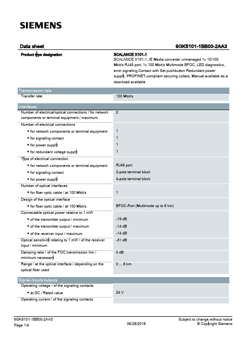
24 V
6GK5101-1BB00-2AA3 Page 1/4
06/28/2018
Subject to change without notice © Copyright Siemens
● at DC / maximum
Supply voltage, current consumption, power loss Supply voltage ● external ● external Type of voltage / of the supply voltage Product component / fusing at power supply input Fuse protection type / at input for supply voltage Consumed current ● maximum Power loss [W] ● at DC / at 24 V
Compact 40 mm 125 mm 124 mm 0.55 kg
Yes Yes Yes
No No
FM3611: Class 1, Divison 2, Group A, B, C, D / T.., Class 1, Zone 2, Group IIC, T.. EN 600079-15 II 3 G EEx nA II T.. KEMA 06 ATEX 0021 X
Yes
Yes Yes Yes Yes Yes No 134 y
/snst
/simatic-net https:// /industry/infocenter /bilddb /cax https://
Security information
UL 60950-1, CSA C22.2 No. 60950-1 UL 1604 and UL 2279-15 (Hazardous Location), Class 1 / Division 2 / Group A, B, C, D / T.., Class 1 / Zone 2 / Group IIC / T.. EN 61000-6-3 EN 61000-6-4:2001 EN 61000-6-2:2001, EN 61000-6-4:2001 Yes Yes Yes
DS-K1808A 系列读卡器 用户手册说明书

DS-K1808A系列读卡器用户手册法律声明版权所有©杭州海康威视数字技术股份有限公司2020。
保留一切权利。
本手册的任何部分,包括文字、图片、图形等均归属于杭州海康威视数字技术股份有限公司或其关联公司(以下简称“海康威视”)。
未经书面许可,任何单位或个人不得以任何方式摘录、复制、翻译、修改本手册的全部或部分。
除非另有约定,海康威视不对本手册提供任何明示或默示的声明或保证。
关于本产品本手册描述的产品仅供中国大陆地区销售和使用。
本产品只能在购买地所在国家或地区享受售后服务及维保方案。
关于本手册本手册仅作为相关产品的指导说明,可能与实际产品存在差异,请以实物为准。
因产品版本升级或其他需要,海康威视可能对本手册进行更新,如您需要最新版手册,请您登录海康威视官网查阅( )。
海康威视建议您在专业人员的指导下使用本手册。
商标声明• 为海康威视的注册商标。
•本手册涉及的其他商标由其所有人各自拥有。
责任声明•在法律允许的最大范围内,本手册以及所描述的产品(包含其硬件、软件、固件等)均“按照现状”提供,可能存在瑕疵或错误。
海康威视不提供任何形式的明示或默示保证,包括但不限于适销性、质量满意度、适合特定目的等保证;亦不对使用本手册或使用海康威视产品导致的任何特殊、附带、偶然或间接的损害进行赔偿,包括但不限于商业利润损失、系统故障、数据或文档丢失产生的损失。
•您知悉互联网的开放性特点,您将产品接入互联网可能存在网络攻击、黑客攻击、病毒感染等风险,海康威视不对因此造成的产品工作异常、信息泄露等问题承担责任,但海康威视将及时为您提供产品相关技术支持。
•使用本产品时,请您严格遵循适用的法律法规,避免侵犯第三方权利,包括但不限于公开权、知识产权、数据权利或其他隐私权。
您亦不得将本产品用于大规模杀伤性武器、生化武器、核爆炸或任何不安全的核能利用或侵犯人权的用途。
•如本手册内容与适用的法律相冲突,则以法律规定为准。
数据安全声明•您在使用产品的过程中,将收集、存储与使用个人数据。
JMT1808R 微控制器用户手册说明书

JMT1808R MCU用户手册江苏宏云技术有限公司*************Dec. 2016 V1.12微控制器JMT1808R 1产品概述 (20)1.1功能描述 (20)1.2主要特性 (20)1.3框图 (22)1.4应用范围 (22)1.5引脚配置 (23)1.5.1 LQFP48L引脚图 (23)1.5.2 LQFP32L引脚图 (24)1.5.3 QFN32L引脚图 (25)1.5.4 TSSOP28L引脚图 (26)1.5.5 引脚说明 (27)2电源管理(PMU) (30)2.1概述 (30)2.2低功耗控制 (30)2.2.1 降低系统时钟频率 (31)2.2.2 外设时钟门控 (32)2.2.3 关闭模拟模块 (32)2.2.4 四种低功耗模式 (32)2.2.5 OSC开关说明 (34)2.3寄存器 (34)2.3.1 低功耗控制寄存器(PMUCTR) [0xA1] (35)3时钟复位管理(CRM) (36)3.1时钟管理 (36)3.1.1 概述 (36)3.1.2 框图 (36)3.1.3 功能描述 (37)3.1.4 寄存器描述 (42)3.2复位管理 (52)3.2.1 概述 (52)3.2.2 框图 (53)3.2.3 功能描述 (53)3.2.4 寄存器 (56)1微控制器JMT1808R4JMT51 MCU核 (61)4.1概述 (61)4.2指令集 (61)5JMT018 DSP核 (67)5.1概述 (67)5.1.1 框图 (67)5.1.2 系统总线 (67)5.1.3 运算单元(ALU) (68)5.1.4 乘累加单元(MAC) (68)5.1.5 除法单元(DIV) (68)5.1.6 硬件循环(HW loop) (69)5.1.7 数据传输 (69)5.1.8 存储单元 (69)5.2指令集 (69)5.2.1 数据传输指令 (69)5.2.2 算术运算指令 (71)5.2.3 移位运算指令 (72)5.2.4 逻辑运算指令 (73)5.2.5 乘法运算指令 (73)5.2.6 并行运算指令 (74)5.2.7 程序控制指令 (77)5.3数据运算器 (78)5.3.1 通用寄存器 (78)5.3.2 累加器A (79)5.3.3 乘法 (83)5.3.4 乘加运算 (84)5.3.5 加减运算 (86)5.3.6 移位运算 (86)5.3.7 四舍五入方法 (87)5.4DSP存储空间 (87)5.4.1 数据存储空间 (87)5.4.2 程序存储空间 (88)5.5DSP工作配置 (89)2微控制器JMT1808R 5.6DSP代码生成与下载 (89)5.6.1 DSP代码生成 (89)5.6.2 DSP代码下载 (89)5.7DSP内部寄存器 (90)5.7.1 DSP通用寄存器R0 (90)5.7.2 DSP通用寄存器R1 (91)5.7.3 DSP通用寄存器R2 (91)5.7.4 DSP通用寄存器R3 (91)5.7.5 DSP通用寄存器R4 (91)5.7.6 DSP通用寄存器R5 (91)5.7.7 DSP通用寄存器R6 (91)5.7.8 DSP通用寄存器R7 (91)5.7.9 X数据空间指针寄存器DP0 (92)5.7.10 Y数据空间指针寄存器DP1 (92)5.7.11 DSP程序地址指针寄存器PC (92)5.7.12 乘法及乘加结果寄存器A (92)5.7.13 LINK寄存器 (92)5.7.14 状态寄存器PSR (92)5.7.15 模式寄存器PMR (93)5.7.16 硬件循环次数寄存器LOOP (93)5.7.17 硬件循环指令个数寄存器LIR (94)5.8JMT51访问DSP寄存器 (94)5.8.1 DSP配置寄存器(DSP_CFG) [0xD4] (95)5.8.2 DSP运行状态寄存器(DSP_STA) [0xD1] (95)5.8.3 PC寄存器低字节(DSP_PCL) [0xD2] (96)5.8.4 PC寄存器高字节(DSP_PCH) [0xD3] (96)5.8.5 R0寄存器低字节(DSP_R0L) [0xD9] (96)5.8.6 R0寄存器高字节(DSP_R0H) [0xDA] (96)5.8.7 R1寄存器低字节(DSP_R1L) [0xDB] (96)5.8.8 R1寄存器高字节(DSP_R1H) [0xDC] (97)5.8.9 R2寄存器低字节(DSP_R2L) [0xDD] (97)5.8.10 R2寄存器高字节(DSP_R2H) [0xDE] (97)5.8.11 R3寄存器低字节(DSP_R3L) [0xDF] (97)5.8.12 R3寄存器高字节(DSP_R3H) [0xE1] (97)5.8.13 R4寄存器低字节(DSP_R4L) [0xE2] (97)3微控制器JMT1808R45.8.14 R4寄存器高字节(DSP_R4H) [0xE3] (97)5.8.15 R5寄存器低字节(DSP_R5L) [0xE4] (98)5.8.16 R5寄存器高字节(DSP_R5H) [0xE5] (98)5.8.17 R6寄存器低字节(DSP_R6L) [0xE6] (98)5.8.18 R6寄存器高字节(DSP_R6H) [0xE7] (98)5.8.19 R7寄存器低字节(DSP_R7L) [0xE9] (98)5.8.20 R7寄存器高字节(DSP_R7H) [0xEA] (98)5.8.21 DP0寄存器低字节(DSP_DP0L) [0xEB] (98)5.8.22 DP0寄存器高字节(DSP_DP0H) [0xEC] (99)5.8.23 DP1寄存器低字节(DSP_DP1L) [0xED] (99)5.8.24 DP1寄存器高字节(DSP_DP1H) [0xEE] (99)5.8.25 A寄存器7~0比特(DSP_A0L) [0xEF] (99)5.8.26 A寄存器15~8比特(DSP_A0H) [0xF1] (99)5.8.27 A寄存器23~16比特(DSP_A1L) [0xF2] (99)5.8.28 A寄存器31~24比特(DSP_A1H) [0xF3] (99)5.8.29 A寄存器39~32比特(DSP_A2) [0xF4] (100)5.8.30 LNKR寄存器低字节(DSP_LNKRL) [0xF5] (100)5.8.31 LNKR寄存器高字节(DSP_LNKRH) [0xF6] (100)5.8.32 PSR寄存器低字节(DSP_PSRL) [0xF7] (100)5.8.33 PSR寄存器高字节(DSP_PSRH) [0xF9] (101)5.8.34 PMR寄存器低字节(DSP_PMRL) [0xFA] (101)5.8.35 PMR寄存器高字节(DSP_PMRH) [0xFB] (101)5.8.36 LOOP寄存器低字节(DSP_LOOPL) [0xFC] (101)5.8.37 LOOP寄存器高字节(DSP_LOOPH) [0xFD] (101)5.8.38 LIR寄存器低字节(DSP_LIRL) [0xFE] (102)5.8.39 LIR寄存器高字节(DSP_LIRH) [0xFF] (102)6中断 (103)6.1概述 (103)6.2外部中断(INT0/INT1) (105)6.3中断优先级 (105)6.4中断处理过程 (106)6.5中断响应时间 (106)6.6中断寄存器 (107)微控制器JMT1808R6.6.1 中断使能寄存器0(IEN0) [0xA8] (107)6.6.2 中断使能寄存器1(IEN1) [0xB8] (108)6.6.3 中断使能寄存器2 (IEN2) [0xC0] (109)6.6.4 中断优先级寄存器0 (IP0) [0xB9] (109)6.6.5 中断优先级寄存器1(IP1) [0xBA] (110)6.6.6 中断优先级寄存器2(IP2) [0xBB] (111)7存储器 (112)7.1JMT51存储器 (112)7.1.1 程序存储器 (112)7.1.2 外部数据存储器 (113)7.1.3 内部数据存储器 (113)7.1.4 特殊功能寄存器 (115)7.2JMT018存储器 (120)7.3存储器访问冲突说明 (121)7.4JMT51核寄存器 (122)7.4.1 ACC寄存器(A) [0xE0] (122)7.4.2 B寄存器(B) [0xF0] (122)7.4.3 堆栈指针(SP) [0x81] (122)7.4.4 程序状态字寄存器(PSW) [0xD0] (123)7.4.5 数据指针低字节(DPL) [0x82] (124)7.4.6 数据指针高字节(DPH) [0x83] (124)7.4.7 MOVX指令设置寄存器(MOVXCON) [0x86] (124)7.5P AGE堆栈寄存器 (125)7.5.1 SFR PAGE寄存器(SFRPAGE) [0x84] (125)7.5.2 PAGE堆栈使能寄存器(SFRPGEN) [0x85] (126)7.5.3 PAGE堆栈寄存器0(PGSTACK0) [0x91] (126)7.5.4 PAGE堆栈寄存器1(PGSTACK1) [0x92] (126)7.5.5 PAGE堆栈寄存器2(PGSTACK2) [0x93] (126)7.5.6 PAGE堆栈寄存器3(PGSTACK3) [0x94] (127)8Flash存储器 (128)8.1概述 (128)8.2FLASH操作 (128)8.2.1 FLASH数据读取 (128)5微控制器JMT1808R68.2.2 FLASH扇区擦除 (129)8.2.3 FLASH编程 (129)8.3FLASH寄存器 (130)8.3.1 FLASH控制寄存器(FLSC) [0xF9] (130)8.3.2 FLASH关键字寄存器(FLSK) [0xFA] (130)9看门狗定时器(WDT) (131)9.1概述 (131)9.2功能描述 (131)9.3寄存器 (131)9.3.1 看门狗分频系数寄存器(WDTCKDIV) [0xD9] (131)9.3.2 看门狗比较值寄存器(WDTINT) [0xDA] (132)9.3.3 看门狗中断标志寄存器(WDTINTF) [0xDB] (132)9.3.4 看门狗喂狗寄存器(WDTLD) [0xDC] (133)9.3.5 看门狗启停寄存器(WDTST) [0xDD] (133)10实时时钟(RTC) (134)10.1概述 (134)10.2实时时钟 (134)10.3闹钟 (136)10.4RTC时钟调校 (136)10.5实时时钟寄存器更新 (137)10.6实时时钟寄存器读取 (137)10.7RTC中断 (137)10.8RTC寄存器 (138)10.8.1 RTC控制寄存器0(RTCCON0) [0xA9] (138)10.8.2 RTC控制寄存器1(RTCCON1) [0xAA] (139)10.8.3 RTC时标控制寄存器(RTCTMC) [0xAB] (140)10.8.4 RTC秒寄存器(RTCSEC) [0xAC] (140)10.8.5 RTC分钟寄存器(RTCMIN) [0xAD] (141)10.8.6 RTC小时寄存器(RTCHOUR) [0xAE] (141)10.8.7 RTC星期寄存器(RTCWEEK) [0xAF] (141)10.8.8 RTC日寄存器(RTCDAY) [0xB1] (141)10.8.9 RTC月寄存器(RTCMON) [0xB2] (141)微控制器JMT1808R10.8.10 RTC年寄存器(RTCYEAR) [0xB3] (142)10.8.11 闹钟0秒寄存器(AL0SEC) [0xB4] (142)10.8.12 闹钟0分钟寄存器(AL0MIN) [0xB5] (142)10.8.13 闹钟0小时寄存器(AL0HOUR) [0xB6] (142)10.8.14 闹钟0星期寄存器(AL0WEEKS) [0xB7] (142)10.8.15 闹钟1分钟寄存器(AL1MIN) [0xB9] (143)10.8.16 闹钟1小时寄存器(AL1HOUR) [0xBA] (143)10.8.17 闹钟1日寄存器(AL1DAY) [0xBB] (143)10.8.18 闹钟1月寄存器(AL1MON) [0xBC] (144)10.8.19 RTC时钟调校寄存器0(RTCADJ0) [0xBD] (144)10.8.20 RTC时钟调校寄存器1(RTCADJ1) [0xBE] (144)10.8.21 RTC中断使能寄存器(RTCIE) [0xBF] (144)10.8.22 RTC中断标志寄存器(RTCIF) [0xC7] (145)11定时器/计数器(TIMER) (146)11.1概述 (146)11.2TIMER管脚配置 (146)11.3Timer0工作模式 (146)11.3.1 模式0(13位定时器/计数器) (146)11.3.2 模式1(16位定时器/计数器) (147)11.3.3 模式2(8位自动重装定时器/计数器) (147)11.3.4 模式3(两个8比特定时器) (148)11.4Timer1工作模式 (149)11.4.1 模式0(13位定时器/计数器) (149)11.4.2 模式1(16位定时器/计数器) (149)11.4.3 模式2(8位自动重装定时器/计数器) (150)11.5Timer2工作模式 (150)11.5.1 模式0(13位定时器/计数器) (150)11.5.2 模式1(16位定时器/计数器) (151)11.5.3 模式2(16位自动重装定时器/计数器) (151)11.5.4 模式3(1个8比特定时器/计数器) (152)11.6TIMER寄存器 (152)11.6.1 Timer0/1控制寄存器(TCON) [0x88] (153)11.6.2 Timer0/1模式寄存器(TMOD) [0x89] (154)7微控制器JMT1808R811.6.3 Timer0低8位(TL0) [0x8A] (155)11.6.4 Timer1低8位(TL1) [0x8B] (155)11.6.5 Timer0高8位(TH0) [0x8C] (155)11.6.6 Timer1高8位(TH1) [0x8D] (155)11.6.7 Timer0/1预分频控制器(TPSC) [0x8E] (155)11.6.8 Timer2控制寄存器(T2CON) [0xD1] (156)11.6.9 Timer2重载寄存器低8位(RL2) [0xD2] (156)11.6.10 Timer2重载寄存器高8位(RH2) [0xD3] (156)11.6.11 Timer2低8位(TL2) [0xD4] (157)11.6.12 Timer2高8位(TH2) [0xD5] (157)11.6.13 Timer2预分频控制器(T2PSC) [0xD6] (157)12高级定时器(PWM) (158)12.1概述 (158)12.2特性 (158)12.3框图 (160)12.4输入输出引脚配置 (160)12.5功能描述 (160)12.5.1 计数器 (161)12.5.2 输入捕获功能 (173)12.5.3 从模式控制 (175)12.5.4 输出比较功能 (181)12.5.5 主模式控制 (207)12.5.6 中断 (209)12.5.7 高级定时器同步 (211)12.6寄存器描述 (216)12.6.1 TIMx控制寄存器0 (TIMx_CONR0) [TIM0:0xBB/TIM1:0xFB] (221)12.6.2 TIMx控制寄存器1 (TIMx_CONR1) [TIM0:0x89/TIM1:0xC9] (223)12.6.3 TIMx控制寄存器2 (TIMx_CONR2) [TIM0:0x8A/TIM1:0xCA] (224)12.6.4 TIMx控制寄存器3 (TIMx_CONR3) [TIM0:0x8B/TIM1:0xCB] (225)12.6.5 TIMx从模式控制寄存器0 (TIMx_TGICR0) [TIM0:0x8C/TIM1:0xCC] (226)12.6.6 TIMx从模式控制寄存器1 (TIMx_TGICR1) [TIM0:0x8D/TIM1:0xCD] (228)12.6.7 TIMx中断使能寄存器0 (TIMx_IER) [TIM0:0x8E/TIM1:0xCE] (230)12.6.8 TIMx中断使能寄存器1(TIMx_IER_NOCMP)[TIM0:0xB7/TIM7:0xF7] 23112.6.9 TIMx通道CC0输入捕获/输出比较模式控制寄存器(TIMx_CC0MR)[TIM0:0x8F/TIM1:0xCF] (231)12.6.10 TIMx通道CC1输入捕获/输出比较模式控制寄存器(TIMx_CC1MR)[TIM0:0x91/TIM1:0xD1] (236)12.6.11 TIMx通道CC2输入捕获/输出比较模式控制寄存器(TIMx_CC2MR)[TIM0:0x92/TIM1:0xD2] (241)12.6.12 TIMx通道CC3输入捕获/输出比较模式控制寄存器(TIMx_CC3MR)[TIM0:0x93/TIM1:0xD3] (245)12.6.13 TIMx通道使能控制寄存器(TIMx_CCENR) [TIM0:0x94/TIM1:0xD4] (249)12.6.14 TIMx通道极性控制寄存器(TIMx_CCPS) [TIM0:0x95/TIM1:0xD5] (251)12.6.15 TIMx死区时间寄存器(TIMx_DTG) [TIM0:0x96/TIM1:0xD6] (252)12.6.16 TIMx周期值自动装载寄存器的低8位(TIMx_ARRL) [TIM0:0x97/TIM1:0xD7]25212.6.17 TIMx周期值自动装载寄存器的高8位(TIMx_ARRH) [TIM0:0x99/TIM1: 0xD9]25312.6.18 TIMx预分频寄存器的低8位(TIMx_PSCL) [TIM0:0x9A/TIM1: 0xDA] (253)12.6.19 TIMx预分频寄存器的高8位(TIMx_PSCH) [TIM0:0x9B/TIM1:0xDB] (253)12.6.20 TIMx重复计数寄存器(TIMx_RCR) [TIM0:0x9C/TIM1:0xDC] (254)12.6.21 TIMx通道CC0捕获/向上计数比较寄存器的低8位(TIMx_CC0RUL)[TIM0:0x9D/ TIM1:0xDD] (254)12.6.22 TIMx通道CC0捕获/向上计数比较寄存器的高8位(TIMx_CC0RUH)[TIM0:0x9E/TIM1:0xDE] (255)12.6.23 TIMx通道CC0向下计数比较寄存器的低8位(TIMx_CC0RDL) [TIM0:0x9F/ TIM1:0xDF] (256)12.6.24 TIMx通道CC0向下计数比较寄存器的高8位(TIMx_CC0RDH) [TIM0:0xA1/ TIM1:0xE1] (257)12.6.25 TIMx通道CC1捕获/向上计数比较寄存器的低8位(TIMx_CC1RUL)[TIM0:0xA2/TIM1:0xE2] (258)12.6.26 TIMx通道CC1捕获/向上计数比较寄存器的高8位(TIMx_CC1RUH)[TIM0:0xA3/TIM1:0xE3] (259)12.6.27 TIMx通道CC1向下计数比较寄存器的低8位(TIMx_CC1RDL)[TIM0:0xA4/TIM1:0xE4] (260)12.6.28 TIMx通道CC1向下计数比较寄存器的高8位(TIMx_CC1RDH)[TIM0:0xA5/TIM1:0xE5] (260)12.6.29 TIMx通道CC2捕获/向上计数比较寄存器的低8位(TIMx_CC2RUL)[TIM0:0xA6/TIM1:0xE6] (261)12.6.30 TIMx通道CC2捕获/向上计数比较寄存器的高8位(TIMx_CC2RUH)[TIM0:0xA7/TIM1:0xE7] (262)12.6.31 TIMx通道CC2向下计数比较寄存器的低8位(TIMx_CC2RDL)[TIM0:0xA9/TIM0:0xE9] (263)12.6.32 TIMx通道CC2向下计数比较寄存器的高8位(TIMx_CC2RDH)[TIM0:0xAA/TIM1:0xEA] (264)12.6.33 TIMx通道CC3捕获/向上计数比较寄存器的低8位(TIMx_CC3RUL)[TIM0:0xAB/TIM1:0xEB] (265)12.6.34 TIMx通道CC3捕获/向上计数比较寄存器的高8位(TIMx_CC3RUH)[TIM0:0xAC/TIM1:0xEC] (266)12.6.35 TIMx通道CC3向下计数比较寄存器的低8位(TIMx_CC3RDL)[TIM0:0xAD/TIM1:0xED] (267)12.6.36 TIMx通道CC3向下计数比较寄存器的高8位(TIMx_CC3RDH)[TIM0:0xAE/TIM1:0xEE] (268)12.6.37 TIMx刹车控制寄存器(TIMx_BRKC) [TIM0:0xAF/TIM1:0xEF] (269)12.6.38 TIMx事件产生寄存器(TIMx_EGR) [TIM0:0xB1/TIM1:0xF1] (271)12.6.39 TIMx互补模式控制寄存器(TIMx_CMPLMTARY) [TIM0:0xB2/TIM1:0xF2]27312.6.40 TIMx中断标志寄存器0 (TIMx_ISR0) [TIM0:0xB3/TIM1:0xF3] (273)12.6.41 TIMx中断标志寄存器1 (TIMx_ISR1) [TIM0:0xB4/TIM1:0xF4] (274)12.6.42 TIMx中断标志寄存器2 (TIMx_ISR2) [TIM0:0xB9/TIM1:0xF9] (275)12.6.43 TIMx计数器的低8位(TIMx_CNTL) [TIM0:0xB5/TIM1:0xF5] (276)12.6.44 TIMx计数器的高8位(TIMx_CNTH) [TIM0:0xB6/TIM1:0xF6] (276)13CORDIC协处理器 (277)13.1概述 (277)13.2功能描述 (278)13.2.1 输入数据格式 (278)13.2.2 结果数据归一化 (278)13.2.3 CORDIC调度 (279)13.2.4 CORDIC中断 (280)13.2.5 CORDIC精度 (280)13.3CORDIC 寄存器 (281)13.3.1 JMT51 MCU调度寄存器 (281)13.3.2 JMT018 DSP指令调度寄存器 (284)14通用异步收发传输器(UART) (287)14.1概述 (287)14.2框图 (287)14.3UART管脚配置 (288)14.4UART工作模式 (288)14.4.1 标准UART工作模式0:同步移位寄存器 (288)14.4.2 标准UART工作模式1:8位UART,波特率可变 (289)14.4.3 标准UART工作模式2:9位UART,波特率固定 (290)14.4.4 标准UART工作模式3:9位UART,波特率可变 (290)14.4.5 38KHz红外调制发送 (291)14.4.6 IrDA(SIR)红外通信 (292)14.5UART多机通信 (292)14.6UART奇偶校验 (293)14.7UART波特率计算 (293)14.8UART寄存器 (302)14.8.1 UART0控制寄存器(S0CON) [0x98] (302)14.8.2 UART0数据缓冲寄存器(S0BUF) [0x99] (303)14.8.3 UART0波特率重载寄存器低8位(S0RELL) [0x9A] (303)14.8.4 UART0波特率重载寄存器高2位(S0RELH) [0x9B] (304)14.8.5 UART0红外控制寄存器(S0IRCON) [0x9C] (304)14.8.6 UART1控制寄存器(S1CON) [0xF1] (305)14.8.7 UART1数据缓冲寄存器(S1BUF) [0xF2] (305)14.8.8 UART1波特率重载寄存器低8位(S1RELL) [0xF3] (306)14.8.9 UART1波特率重载寄存器高2位(S1RELH) [0xF4] (306)14.8.10 UART1红外控制寄存器(S1IRCON) [0xF5] (306)15I2C接口 (308)15.1概述 (308)15.2框图 (308)15.3I2C管脚配置 (308)15.4I2C模块连接 (308)15.5I2C数据格式 (309)15.5.2 读写控制比特 (309)15.5.3 反馈(ACK) (310)15.5.4 起始条件和结束条件 (310)15.5.5 数据格式 (310)15.5.6 时钟同步 (311)15.5.7 仲裁 (311)15.6I2C时钟产生 (312)15.7I2C工作模式 (313)15.7.1 从机模式 (313)15.7.2 主机模式 (315)15.8I2C中断 (318)15.9I2C寄存器 (319)15.9.1 I2C控制寄存器(I2CCON) [0xE1] (319)15.9.2 I2C从机地址寄存器低8位(I2CSADDRL) [0xE2] (320)15.9.3 I2C从机地址寄存器高2位(I2CSADDRH) [0xE3] (320)15.9.4 I2C本机地址寄存器低8位(I2COADDRL) [0xE4] (321)15.9.5 I2C本机地址寄存器高2位(I2COADDRH) [0xE5] (321)15.9.6 I2C工作时钟分频控制寄存器(I2CDIV) [0xE6] (321)15.9.7 I2C时钟SCL低电平时间配置寄存器(I2CDUTYL) [0xE7] (322)15.9.8 I2C时钟SCL高电平时间配置寄存器(I2CDUTYH) [0xE9] (322)15.9.9 I2C数据SDA保持时间配置寄存器(I2CHOLD) [0xEA] (322)15.9.10 I2C数据写缓冲寄存器(I2CWBUF) [0xEB] (323)15.9.11 I2C数据读缓冲寄存器(I2CRBUF) [0xEC] (323)15.9.12 I2C状态寄存器(I2CSTS) [0xED] (323)15.9.13 I2C中断标志寄存器(I2CISC) [0xEE] (324)15.9.14 I2C中断使能寄存器(I2CIEN) [0xEF] (325)16串行外设接口(SPI) (326)16.1概述 (326)16.2框图 (326)16.3SPI管脚配置 (326)16.4SPI主/从机互连 (327)16.4.1 4线互连模式 (327)16.5SPI时序设置 (328)16.6数据发送和接收过程 (329)16.6.1 主机模式 (329)16.6.2 从机模式 (331)16.7SPI中断 (332)16.8SPI寄存器 (333)16.8.1 SPI控制寄存器(SPICON) [0xC9] (333)16.8.2 SPI中断使能寄存器(SPIIE) [0xCA] (334)16.8.3 SPI中断标志寄存器(SPIIF) [0xCB] (335)16.8.4 SPI波特率控制寄存器(SPIBR) [0xCC] (335)16.8.5 SPI数据缓冲寄存器(SPIBUF) [0xCD] (336)17模拟/数字转换(ADC)和可编程增益放大器(PGA) (337)17.1概述 (337)17.2ADC转换结果访问方式 (338)17.3ADC输入端口配置 (338)17.4可编程增益放大器(PGA)说明 (339)17.5ADC参考电压配置 (341)17.6ADC转换功能 (341)17.7ADC转换结果数据格式 (342)17.8ADC转换时序 (342)17.9模拟看门狗 (343)17.10外部触发事件 (344)17.11特殊通道序列管理 (346)17.12ADC工作模式 (347)17.12.1 单次转换+非扫描模式 (347)17.12.2 单次转换+扫描模式 (348)17.12.3 连续转换+非扫描模式 (350)17.12.4 连续转换+扫描模式 (351)17.13双ADC协同工作模式 (353)17.13.1 独立模式 (353)17.13.2 普通同步模式 (353)17.13.4 普通交叉模式 (355)17.13.5 特殊交替触发模式 (355)17.13.6 普通同步+特殊同步模式 (356)17.13.7 普通同步+特殊交替触发模式 (357)17.13.8 普通交叉+特殊同步模式 (358)17.14中断处理 (359)17.15ADC寄存器 (360)17.15.1 JMT51访问ADC寄存器 (360)17.15.2 JMT018访问ADC寄存器 (391)18模拟比较器(CMP) (393)18.1模拟比较器概述 (393)18.2低压检测 (394)18.2.1 低压检测保护程序示例 (395)18.3模拟比较器寄存器 (396)18.3.1 模拟比较器使能寄存器(CMPEN) [0x91] (396)18.3.2 模拟比较器中断寄存器(CMPINT) [0x92] (397)18.3.3 模拟比较器比较结果寄存器(CMPFLAG) [0x93] (397)18.3.4 模拟比较器滤波选择寄存器(CMPFT) [0x94] (398)18.3.5 模拟比较器VDD分压寄存器(CMPVDD) [0x95] (398)18.3.6 模拟比较器参考电压选择寄存器(CMPREF) [0x96] (398)19通用输入/输出(GPIO) (400)19.1管脚设置 (400)19.2管脚功能复用 (403)19.3PWM管脚特殊复用 (407)19.3.1 PWM输出复用 (407)19.3.2 PWM刹车复用 (407)19.4管脚数据寄存器读写 (408)19.5外设管脚复用配置 (408)19.6管脚滤波 (415)19.7INT0中断 (415)19.8INT1中断 (418)19.9P A0唤醒 (421)19.10GPIO寄存器 (421)19.10.1 PA0数字I/O控制寄存器(PA0CTRL) [0x99] (424)19.10.2 PA1数字I/O控制寄存器(PA1CTRL) [0x9A] (425)19.10.3 PA2数字I/O控制寄存器(PA2CTRL) [0x9B] (426)19.10.4 PA3数字I/O控制寄存器(PA3CTRL) [0x9C] (427)19.10.5 PA4数字I/O控制寄存器(PA4CTRL) [0x9D] (428)19.10.6 PA5数字I/O控制寄存器(PA5CTRL) [0x9E] (428)19.10.7 PA6数字I/O控制寄存器(PA6CTRL) [0x9F] (429)19.10.8 PA7数字I/O控制寄存器(PA7CTRL) [0xC3] (430)19.10.9 PB0数字I/O控制寄存器(PB0CTRL) [0xA1] (431)19.10.10 PB1数字I/O控制寄存器(PB1CTRL) [0xA2] (432)19.10.11 PB2数字I/O控制寄存器(PB2CTRL) [0xA3] (432)19.10.12 PB3数字I/O控制寄存器(PB3CTRL) [0xA4] (433)19.10.13 PB4数字I/O控制寄存器(PB4CTRL) [0xA5] (434)19.10.14 PB5数字I/O控制寄存器(PB5CTRL) [0xA6] (435)19.10.15 PB6数字I/O控制寄存器(PB6CTRL) [0xA7] (436)19.10.16 PB7数字I/O控制寄存器(PB7CTRL) [0xC4] (436)19.10.17 PC0数字I/O控制寄存器(PC0CTRL) [0xA9] (437)19.10.18 PC1数字I/O控制寄存器(PC1CTRL) [0xAA] (438)19.10.19 PC2数字I/O控制寄存器(PC2CTRL) [0xAB] (439)19.10.20 PC3数字I/O控制寄存器(PC3CTRL) [0xAC] (440)19.10.21 PC4数字I/O控制寄存器(PC4CTRL) [0xAD] (440)19.10.22 PC5数字I/O控制寄存器(PC5CTRL) [0xAE] (441)19.10.23 PC6数字I/O控制寄存器(PC6CTRL) [0xAF] (442)19.10.24 PC7数字I/O控制寄存器(PC7CTRL) [0xC5] (443)19.10.25 PD0数字I/O控制寄存器(PD0CTRL) [0xB1] (444)19.10.26 PD1数字I/O控制寄存器(PD1CTRL) [0xB2] (444)19.10.27 PD2数字I/O控制寄存器(PD2CTRL) [0xB3] (445)19.10.28 PD3数字I/O控制寄存器(PD3CTRL) [0xB4] (446)19.10.29 PD4数字I/O控制寄存器(PD4CTRL) [0xB5] (447)19.10.30 PD5数字I/O控制寄存器(PD5CTRL) [0xB6] (448)19.10.31 PD6数字I/O控制寄存器(PD6CTRL) [0xB7] (448)19.10.32 PD7数字I/O控制寄存器(PD7CTRL) [0xC6] (449)19.10.33 PE0数字I/O控制寄存器(PE0CTRL) [0xB9] (450)19.10.34 PE1数字I/O控制寄存器(PE1CTRL) [0xBA] (451)19.10.35 PE2数字I/O控制寄存器(PE2CTRL) [0xBB] (452)19.10.36 PE3数字I/O控制寄存器(PE3CTRL) [0xBC] (452)19.10.37 PE4数字I/O控制寄存器(PE4CTRL) [0xBD] (453)19.10.38 PE5数字I/O控制寄存器(PE5CTRL) [0xBE] (454)19.10.39 PE6数字I/O控制寄存器(PE6CTRL) [0xBF] (455)19.10.40 PE7数字I/O控制寄存器(PE7CTRL) [0xC7] (456)19.10.41 PG0数字I/O控制寄存器(PG0CTRL) [0xC1] (456)19.10.42 PG1数字I/O控制寄存器(PG1CTRL) [0xC2] (457)19.10.43 PA转换速率寄存器(PASR) [0xC9] (458)19.10.44 PB转换速率寄存器(PBSR) [0xCA] (459)19.10.45 PC转换速率寄存器(PCSR) [0xCB] (460)19.10.46 PD转换速率寄存器(PDSR) [0xCC] (461)19.10.47 PE转换速率寄存器(PESR) [0xCD] (461)19.10.48 PG转换速率寄存器(PGSR) [0xCE] (462)19.10.49 PA驱动能力寄存器(PADR) [0xD1] (463)19.10.50 PB驱动能力寄存器(PBDR) [0xD2] (464)19.10.51 PC驱动能力寄存器(PCDR) [0xD3] (464)19.10.52 PD驱动能力寄存器(PDDR) [0xD4] (465)19.10.53 PE驱动能力寄存器(PEDR) [0xD5] (466)19.10.54 PG驱动能力寄存器(PGDR) [0xD6] (467)19.10.55 模拟管脚使能寄存器0(AIOEN0) [0xCF] (467)19.10.56 模拟管脚使能寄存器1(AIOEN1) [0xD7] (469)19.10.57 复位管脚滤波选择寄存器(NRSTFQS) [0xD9] (470)19.10.58 唤醒使能寄存器(WKUPEN) [0xDB] (470)19.10.59 INT0上升沿中断使能寄存器(INT0PE) [0xDC] (471)19.10.60 INT0下降沿中断使能寄存器(INT0NE) [0xDD] (471)19.10.61 INT0中断使能寄存器(INT0EN) [0xDE] (472)19.10.62 INT0中断控制寄存器(INT0CON) [0xDF] (473)19.10.63 INT1上升沿中断使能寄存器(INT1PE) [0xE1] (474)19.10.64 INT1下降沿中断使能寄存器(INT1NE) [0xE2] (475)19.10.65 INT1中断使能寄存器(INT1EN) [0xE3] (476)19.10.66 INT1中断控制寄存器(INT1CON) [0xE4] (477)19.10.67 INT1中断管脚选择寄存器0(INT1SEL0) [0xE5] (478)19.10.68 INT1中断管脚选择寄存器1(INT1SEL1) [0xE6] (479)19.10.69 INT1中断管脚选择寄存器2(INT1SEL2) [0xE7] (480)19.10.70 INT1中断管脚选择寄存器3(INT1SEL3) [0xE9] (480)19.10.71 PWM刹车选择寄存器(PWMBKS) [0xEA] (481)19.10.72 PWM特殊复用输出分组选择寄存器(PWMOSEL) [0xF1] (481)19.10.73 PWM特殊复用输出选择寄存器0(PWMOSEL0) [0xF2] (482)19.10.74 PWM特殊复用输出选择寄存器1(PWMOSEL1) [0xF3] (483)19.10.75 PWM特殊复用输出选择寄存器2(PWMOSEL2) [0xF4] (483)19.10.76 PWM特殊复用输出使能寄存器0(PWMOMUX0) [0xF5] (484)19.10.77 PWM特殊复用输出使能寄存器1(PWMOMUX1) [0xF6] (485)19.10.78 PWM特殊复用输出使能寄存器2(PWMOMUX2) [0xF7] (486)19.10.79 PA输入缓冲使能寄存器(PAIE) [0xF9] (487)19.10.80 PB输入缓冲使能寄存器(PBIE) [0xFA] (488)19.10.81 PC输入缓冲使能寄存器(PCIE) [0xFB] (489)19.10.82 PD输入缓冲使能寄存器(PDIE) [0xFC] (489)19.10.83 PE输入缓冲使能寄存器(PEIE) [0xFD] (490)19.10.84 PG输入缓冲使能寄存器(PGIE) [0xFE] (491)19.10.85 PA数据寄存器(P0) [0x80] (492)19.10.86 PB数据寄存器(P1) [0x90] (492)19.10.87 PC数据寄存器(P2) [0xA0] (492)19.10.88 PD数据寄存器(P3) [0xB0] (492)19.10.89 PE数据寄存器(P4) [0xC8] (492)19.10.90 PG数据寄存器(P6) [0x98] (492)20电气特性 (493)20.1极限参数 (493)20.2工作条件 (493)20.2.1 芯片供电 (493)20.2.2 功耗特性 (493)20.2.3 I/O特性 (494)20.2.4 REGC引脚特性 (495)20.2.5 NRST引脚特性 (495)20.2.6 上电/掉电条件 (495)20.2.7 时钟特性 (496)20.2.8 通信接口 (498)20.2.9 FLASH特性 (501)20.2.10 ADC特性 (501)20.2.11 PGA特性 (502)20.2.12 CMP特性 (502)20.2.13 内部参考电压特性 (503)20.2.14 电气敏感性 (503)21封装特性 (504)21.1LQFP32L (504)21.2LQFP48L (505)21.3QFN32L (507)21.4TSSOP28L (508)1产品概述1.1功能描述JMT1808R是一款内置MCU和DSP的双核SOC芯片。
IPAM-1808 16通道数字量输入输出模块 用户手册
2. IPAM-1808 的数字量输入输出功能 ..................................................................... 9
2.1 数字量输入 ....................................................................................................................... 9 2.2 数字量输出 ..................................................................................................................... 10 2.2.1 输出原理 .............................................................................................................. 10 2.2.2 输出接线方式 ...................................................................................................... 10 2.2.3 数字量输出通道控制 .......................................................................................... 11 2.2.4 屏蔽同步输出 ...................................................................................................... 11 2.3 数字量输入/输出方式选择 ............................................................................................ 11
中文大豪SC511圆头锁眼触屏E
2.1 操作面板说明 ............................................................................................................................... 3 2.2 基本操作........................................................................................................................................4 2.3 花样程序的设定方法 ....................................................................................................................5 2.4 试送布模式确认缝纫花样 .......................................................................................................... 10 2.5 切刀动作的切换 .......................................................................................................................... 13 2.6 布料设定位置的切换方法 .......................................................................................................... 14 2.7 穿线模式...................................................................................................................................... 15
- 1、下载文档前请自行甄别文档内容的完整性,平台不提供额外的编辑、内容补充、找答案等附加服务。
- 2、"仅部分预览"的文档,不可在线预览部分如存在完整性等问题,可反馈申请退款(可完整预览的文档不适用该条件!)。
- 3、如文档侵犯您的权益,请联系客服反馈,我们会尽快为您处理(人工客服工作时间:9:00-18:30)。
VJ OMD - C0G (NP0)Vishay VitramonSurface Mount Multilayer Ceramic Chip Capacitor Solutionsfor Boardflex Sensitive ApplicationsFEATURES•Surface mountable. Precious metal technology,wet build process•OMD-Cap (Open Mode Design) reduce the riskof shorts or low IR because of board flex cracks•High frequency filtering for switching power supplies•Available with 100 % voltage condition,process code “5H” is available for 630 V and lower. Contactmlcc.specials@ for higher voltages•Available with polymer termination for increase resistanceto board flex cracking•Protective surface coating high voltage capacitors mayberequired to prevent surface arcing.APPLICATIONS•Input filter capacitors•Output filter capacitors•Snubber capacitors reduce MOSFET voltage spikes•Lighting BallastsELECTRICAL SPECIFICATIONSNote: Electrical characteristics at + 25 °C unless otherwise stated.Protective surface coating of high voltage capacitors mayberequired to prevent surface arcing.Operating Temperature: - 55 °C to + 125 °C Capacitance Range: 10 pF to 47 nFVoltage Rating: 50 Vdc to 3000 VdcTemperature Coefficient of Capacitance (TCC):C0G: 0 ± 30 ppm/°C from - 55 °C to + 125 °CAging Rate: 0 % maximum per decadeDissipation Factor:0.1 % max. at 1.0 V rms and 1 MHz for values ≤ 1000 pF0.1 % max. at 1.0 V rms and 1 kHz for values > 1000 pFInsulation Resistance (IR):At + 25 °C and rated voltage 100 000 MΩ minimum or 1000 ΩF, whichever is lessAt + 125 °C and rated voltage 10 000 MΩ minimum or 100 ΩF, whichever is less Dielectric Withstanding Voltage (DWV):This is the maximum voltage the capacitors are tested for a 1 to 5 second period and the charge/discharge current does not exceed 50 mA≤200 Vdc: DWV at 250 % of rated voltage500 Vdc: DWV at 200 % of rated voltage630 Vdc: DWV at 150 % of rated voltage1000 Vdc: DWV at 150 % of rated voltage1500 Vdc: DWV at 120 % of rated voltage2000 Vdc: DWV at 120 % of rated voltage3000 Vdc: DWV at 120 % of rated voltage For technical questions, contact: mlcc.specials@ Document Number: 45047VJ OMD - C0G (NP0)Surface Mount Multilayer Ceramic Chip Capacitor Solutions for Boardflex Sensitive ApplicationsVishay VitramonDocument Number: 45047For technical questions, contact: mlcc.specials@Notes:(1)DC voltage rating should not be exceeded in application (2)Process code with 2 digits has to be added•Polymer plus termination “B” termination part number code length dimensions positive tolerances (including bandwidth) above are allowed to increase by the following amounts.1206 and smaller case sizes: Length 0.002" (0.05 mm)1210 and larger case sizes: Length 0.004" (0.1 mm)ORDERING INFORMATIONVJ1206A 101J XB A T## (2) CASE SIZE DIELECTRICCAP ACIT ANCE CODE CAP ACIT ANCE TOLERANCE TERMINA TIONDC VOLT AGE RA TING (1) MARKINGP ACKAGING PROCESSCODE 1206121018081812182522202225A = C0G (NP0)Expressed in picofarads (pF). The first two digits are significant, the third is a multiplier. Example:101= 100 pFF = ± 1 %G = ± 2 %H = ± 3 % J = ± 5 % K = ± 10 %M = ± 20 %X = Ni barrier 100 %Tin plate matte finish F = AgPd B = Polymer 100 % Tinplatematte finish A = 50 V B = 100 V C = 200 V E = 500 V L = 630 V G = 1000 V R = 1500 V F = 2000 V H = 3000 VA = Unmarked T = 7" ReelsR = 11 1/4" Reels B = Bulk W = Waffletray4X = OMD Cap 5H = OMD Cap100 % Voltage condition For technical questions, contact: mlcc.specials@Document Number: 45047VJ OMD - C0G (NP0)Vishay Vitramon Surface Mount Multilayer Ceramic Chip Capacitor Solutionsfor Boardflex Sensitive ApplicationsNote:(1) See soldering recommendations within this data book, or visit /doc?45034OMD - C0G (NP0) CAPACITANCE RANGEEIA CODE VJ1206 (1) VJ1210(1)VJ1808 (1)VOLTAGE (Vdc)501002005006301000150050100200500630100015002000501002005006301000150020003000CAP . CODECAP.10010 pF ••••••••••••••••••••••••12012 pF ••••••••••••••••••••••••15015 pF ••••••••••••••••••••••••18018 pF ••••••••••••••••••••••••22022 pF ••••••••••••••••••••••••27027 pF ••••••••••••••••••••••••33033 pF ••••••••••••••••••••••••39039 pF •••••••••••••••••••••••47047 pF •••••••••••••••••••••••56056 pF •••••••••••••••••••••••68068 pF •••••••••••••••••••••••82082 pF •••••••••••••••••••••••101100 pF •••••••••••••••••••••••121120 pF ••••••••••••••••••••••151150 pF •••••••••••••••••181180 pF •••••••••••••••••221220 pF •••••••••••••••••271270 pF •••••••••••••••331330 pF •••••••••••••••391390 pF •••••••••••••••471470 pF •••••••••••••••561560 pF •••••••••••••••681680 pF •••••••••••••••821820 pF •••••••••••••••1021000 pF •••••••••••••••1221200 pF •••••••••••1521500 pF ••••••••••1821800 pF •••••••••2222200 pF •••••••••2722700 pF ••••••••3323300 pF ••••••••3923900 pF •••••••4724700 pF •••••••5625600 pF ••••6826800 pF •••8228200 pF ••1030.010 µF 1230.012 µF 1530.015 µF 1830.018 µF 2230.022 µF 2730.027 µF 3330.033 µF 3930.039 µF 4730.047 µF 5630.056 µF 6830.068 µF 8230.082 µF 1040.1 µFVJ OMD - C0G (NP0)Surface Mount Multilayer Ceramic Chip Capacitor Solutions for Boardflex Sensitive ApplicationsVishay VitramonDocument Number: 45047For technical questions, contact: mlcc.specials@Note:(1) See soldering recommendations within this data book, or /doc?45034OMD - C0G (NP0) CAPACITANCE RANGEEIA CODE VJ1812 (1)VJ1825 (1)VJ2220 (1)VJ2225 (1)VOLTAGE (VDC)501002005006301000150020003000501002005006301000501002005006301000501002005006301000CAP . CODE CAP.10010 pF •••••••••12012 pF •••••••••15015 pF •••••••••••18018 pF •••••••••••22022 pF •••••••••••27027 pF •••••••••••33033 pF •••••••••••••••39039 pF •••••••••••••••47047 pF •••••••••••••••56056 pF •••••••••••••••68068 pF •••••••••••••••82082 pF •••••••••••••••101100 pF •••••••••••••••121120 pF •••••••••••••••151150 pF •••••••••••••••181180 pF •••••••••••••••221220 pF •••••••••••••••271270 pF •••••••••••••••••••••••••••331330 pF •••••••••••••••••••••••••••391390 pF ••••••••••••••••••••••••••471470 pF ••••••••••••••••••••••••••561560 pF ••••••••••••••••••••••••••681680 pF ••••••••••••••••••••••••••821820 pF ••••••••••••••••••••••••1021000 pF ••••••••••••••••••••••••1221200 pF ••••••••••••••••••••••••1521500 pF ••••••••••••••••••••••••1821800 pF ••••••••••••••••••••••••2222200 pF ••••••••••••••••••••••••2722700 pF ••••••••••••••••••••3323300 pF ••••••••••••••••••••3923900 pF ••••••••••••••••••••4724700 pF •••••••••••••••••••5625600 pF ••••••••••••••6826800 pF ••••••••••••••8228200 pF ••••••••••••••1030.010 µF •••••••••••••1230.012 µF ••••••••••••1530.015 µF •••••••••1830.018 µF •••••••••2230.022 µF ••••••••2730.027 µF •••••••3330.033 µF •••••3930.039 µF •••4730.047 µF •5630.056 µF 6830.068 µF 8230.082 µF 1040.1 µFFor technical questions, contact: mlcc.specials@Document Number: 45047VJ OMD - C0G (NP0)Vishay Vitramon Surface Mount Multilayer Ceramic Chip Capacitor Solutionsfor Boardflex Sensitive ApplicationsVJ OMD - C0G (NP0)Surface Mount Multilayer Ceramic Chip Capacitor Solutions for Boardflex Sensitive ApplicationsVishay VitramonDocument Number: 45047For technical questions, contact: mlcc.specials@BOARDFLEX SENSITIVE APPLICATIONS - SOLUTION:A predominant failure mode in multilayer ceramic chip capacitors is cracking caused by board flexure. Cracks can then create a path for current to pass from one electrode through the dielectric to an opposing electrode or from the terminations at one end of the MLCC through the dielectric to an opposing electrode. This may subsequently result in capacitance loss, leakage - low Insulation Resistance (IR) - and/or more seriously, high current shorts. A short circuit condition in the surface mounted capacitors can cause further failures of downstream components. Vishay’s Open Mode Design Capacitors (VJ OMD - Cap series) reduce the risk of these destructive conditions through MLCC designs that prevent board flexure cracks reaching the opposing electrode.VJ OMD - Cap MLCCs reduce the risk of early field failures associated with board flex cracks. However, it is important to note that even in the open mode designs the presence of flexure related cracks can cause capacitance loss leading to localized stresses on the parts. eventually, depending on the application environment, including such factors and high voltage pulse frequency and thermal cycling this may lead to internal breakdown of the component.POLYMER TERMINATIONPolymer termination provides additional protection against board flexure damage by absorbing greater mechanical and thermal stresses. Components can be packaged, transported, stored and handled the same standard terminated product. Wave and reflow soldering of MLCC does not require modification to equipment and/or process. Polymer termination greatly reduces the risk of mechanical cracking however it does not completely eliminate.STANDARD TERMINATIONOMD CAP PLUS POLYMER TERMINATIONExposed Electrodes = Electrical shortNo Exposed Electrodes = No Electrical short For technical questions, contact: mlcc.specials@Document Number: 45047VJ OMD - C0G (NP0)Vishay Vitramon Surface Mount Multilayer Ceramic Chip Capacitor Solutionsfor Boardflex Sensitive ApplicationsNotes:(1)Vishay Vitramon uses embossed plastic carrier tape(2)REFERENCE: EIA Standard RS 481 - “Taping of Surfance Mount Components for Automatic Placement”(3)N/a = Not availableSTANDARD PACKAGING QUANTITIES (1)(2)(3)7" REEL QUANTITIES11 1/4" AND 13" REELQUANTITIES BULK QUANTITIES BODY SIZE TAPE SIZE PAPER TAPE PACKAGING CODE “C”PLASTIC TAPE PACKAGING CODE “T”PAPER TAPE PACKAGING CODE “P”PLASTIC TAPE PACKAGING CODE “R”VIAL PACKAGING CODE “B”WAFFLE PACKAGING CODE “W”12068 mm N/a 3000N/a 10 0005000N/a 12108 mm N/a 3000N/a 10 0005000N/a 180812 mm N/a 3000N/a 10 0001000N/a 181212 mmN/a1000N/a 50001000N/a 182512 mm N/a 1000N/a 500010001000222012 mm N/a 1000N/a 5000N/a 1000222512 mmN/a1000N/a5000N/a1000Disclaimer Legal Disclaimer NoticeVishayAll product specifications and data are subject to change without notice.Vishay Intertechnology, Inc., its affiliates, agents, and employees, and all persons acting on its or their behalf (collectively, “Vishay”), disclaim any and all liability for any errors, inaccuracies or incompleteness contained herein or in any other disclosure relating to any product.Vishay disclaims any and all liability arising out of the use or application of any product described herein or of any information provided herein to the maximum extent permitted by law. The product specifications do not expand or otherwise modify Vishay’s terms and conditions of purchase, including but not limited to the warranty expressed therein, which apply to these products.No license, express or implied, by estoppel or otherwise, to any intellectual property rights is granted by this document or by any conduct of Vishay.The products shown herein are not designed for use in medical, life-saving, or life-sustaining applications unless otherwise expressly indicated. Customers using or selling Vishay products not expressly indicated for use in such applications do so entirely at their own risk and agree to fully indemnify Vishay for any damages arising or resulting from such use or sale. Please contact authorized Vishay personnel to obtain written terms and conditions regarding products designed for such applications.Product names and markings noted herein may be trademarks of their respective owners.元器件交易网Document Number: 。