BS 341 4-2004 移动式气瓶阀门 第4部分 压力泄放装置
压力容器安全泄放装置范文(二篇)
压力容器安全泄放装置范文压力容器安全泄放装置是一种用于保护压力容器的重要安全设备。
在压力容器内部产生超过安全设计压力的时候,安全泄放装置可以自动打开,将过压气体释放到安全位置,从而保证了压力容器的安全运行。
本文将为您详细介绍压力容器安全泄放装置的定义、分类、工作原理、选型和使用注意事项等方面的内容。
一、定义压力容器安全泄放装置,简称安全泄压装置,是一种在压力容器内压力超过安全设计压力时,自动打开并将过压气体释放到安全位置的装置。
二、分类根据安全泄放装置的工作原理和结构特点,可以将其分为以下几种类型:1. 弹簧式安全泄放装置:通过弹簧的力量实现开启或关闭。
当压力超过设定值时,弹簧失去控制,安全泄放装置自动打开。
2. 膜片式安全泄放装置:通过膜片的变形实现开启或关闭。
当压力超过设定值时,膜片弯曲,安全泄放装置自动打开。
3. 波纹管式安全泄放装置:通过波纹管的弹性变形实现开启或关闭。
当压力超过设定值时,波纹管展开,安全泄放装置自动打开。
4. 磁簧式安全泄放装置:通过磁簧的吸力或排斥力实现开启或关闭。
当压力超过设定值时,磁簧失去控制,安全泄放装置自动打开。
三、工作原理安全泄放装置的工作原理主要取决于其分类。
以弹簧式安全泄放装置为例,其工作原理如下:1. 当压力容器内的压力低于安全设计压力时,安全泄放装置保持关闭状态。
2. 当压力容器内的压力超过安全设计压力时,压力作用于弹簧,使其失去控制。
3. 弹簧失去控制后,安全泄放装置自动打开,过压气体通过泄放通道释放到安全位置。
4. 当压力回落到安全范围内时,安全泄放装置关闭,停止泄放。
四、选型在选择压力容器安全泄放装置时,需要考虑以下几个因素:1. 压力容器的设计压力和工作压力范围。
2. 安全泄放装置的动作压力和泄放能力。
3. 安全泄放装置的材质和耐腐蚀性能。
4. 安全泄放装置的安装方式和连接方式。
五、使用注意事项在使用压力容器安全泄放装置时,需要注意以下几个问题:1. 定期检查安全泄放装置的工作状态和完整性,确保其正常可靠地工作。
bs气瓶阀标准

BS气瓶阀标准1.范围本标准规定了BS气瓶阀的术语和定义、材料、设计、制造、试验方法、检验规则、标志、包装、运输、贮存、安装、使用与维护等方面的要求。
本标准适用于公称工作压力不大于300bar,公称直径不大于50mm的常压或低压气瓶阀。
2.规范性引用文件下列文件对于本文件的应用是必不可少的。
凡是注日期的引用文件,仅注日期的版本适用于本文件。
凡是不注日期的引用文件,其最新版本(包括所有的修改单)适用于本文件。
3.术语和定义本标准所涉及的术语和定义如下:3.1 BS气瓶阀:一种用于控制气体进出气瓶的装置,通常由阀体、阀杆、密封件和紧固件等组成。
3.2 公称直径:表示气瓶阀规格的尺寸,通常以毫米(mm)为单位。
3.3 公称工作压力:表示气瓶阀可承受的最大工作压力,通常以兆帕(MPa)为单位。
3.4 常压气瓶:指工作压力始终保持在0.1~1.6MPa的气瓶。
3.5 低压气瓶:指工作压力保持在0.1MPa以下的气瓶。
4.材料BS气瓶阀的主要材料应符合相关标准的规定,并且应具有足够的强度和耐腐蚀性。
具体要求如下:4.1 阀体:应采用耐腐蚀性良好的材料制成,如不锈钢、铜或铝合金等。
4.2 阀杆:应采用不锈钢或其他具有足够强度和耐腐蚀性的材料制成。
4.3 密封件:应根据使用介质和压力等条件选择合适的材料制成,如橡胶、聚四氟乙烯等。
4.4 紧固件:应采用耐腐蚀性和强度足够高的材料制成,如不锈钢、碳钢等。
5.设计BS气瓶阀的设计应符合相关法规和标准的规定,并且应考虑安全、易于操作和维护等方面的要求。
具体要求如下:5.1 阀体设计应简洁、易于清洗和消毒。
5.2 阀杆设计应合理,易于操作,并且能够承受工作压力。
5.3 密封件设计应能够保证密封性能和使用寿命。
5.4 紧固件设计应能够保证连接牢固、易于拆卸和更换。
6.制造BS气瓶阀的制造过程应符合相关法规和标准的规定,并且应保证产品质量和安全性。
具体要求如下:6.1 制造过程应严格控制原材料的质量和选用合适的加工方法。
常用气体阀门的种类和技术规格
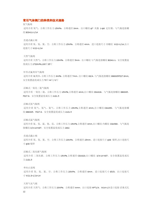
常用气体阀门的种类和技术规格氧气瓶阀适用介质氧气,公称工作压力 15MPa,公称通径 3mm,出口螺纹φ7夹箍1-φ6定位销,与气瓶连接螺纹 BS3411-1/14直通式截止阀适用介质氧、氢、氮、空,公称工作压力 15MPa,公称通径 4mm,进口连接尺寸内螺纹W22×1/14,出口连接尺寸 W22×1/14天然气瓶阀适用介质天然气,公称工作压力 20MPa,公称通径 5mm,出口螺纹与气瓶连接螺纹 BS341-1,安全装置温度或压力 27±3MPa,100℃±5℃针形式氟利昂气瓶阀适用介质氟利昂,公称工作压力 3MPa,公称通径 7mm,出口螺纹 G3/4,与气瓶连接螺纹 GB8335PZ27.8mm,安全装置温度或压力 70℃+4℃/-2℃活瓣式一氧化二氮气瓶阀适用介质一氧化二氮,公称工作压力 15MPa,公称通径 4mm,出口螺纹 CGA326,与气瓶连接螺纹 GB8335,PZ27.8,安全装置温度或压力 21±1.5活瓣式氢气瓶阀适用介质氧气、氢气、氮气,公称工作压力 15MPa,公称通径 4mm,出口螺纹 CGA350,与气瓶连接螺纹 GB8335,PZ27.8,安全装置温度或压力 21±1.5活瓣式氩气瓶阀适用介质氦、氖、氩、氪、氙,公称工作压力 15MPa,公称通径 4mm,出口螺纹内螺纹CGA580,与气瓶连接螺纹 3/4-14-NGT,安全装置温度或压力 28±2直通式截止阀适用介质氧、氢、氮、空,公称工作压力 20MPa,公称通径 25mm,进口连接尺寸φ38银焊,出口连接尺寸φ38银焊活瓣式二氧化碳气瓶阀适用介质二氧化碳,公称工作压力 15MPa,公称通径 CGA320,出口螺纹3/4-14-NGT,安全装置温度或压力 21±1.5单向止逆阀适用介质氧、氢、氮、空,公称工作压力 20MPa,公称通径 6mm,进口连接尺寸 G5/8,出口连接尺寸 W21.8×1/14-LH天然气充气阀适用介质天然气,公称工作压力 20MPa,公称通径 4mm,出口连接 NPT1/4,M14×1.5进口连接活塞式孔12活瓣式氧气瓶阀适用介质氧气、空气、氮气,公称工作压力 20MPa,公称通径 4mm,内螺纹 G5/8,与气瓶连接螺纹 GB8335PZ27.8mm,安全装置或压力 28±2直通式截止阀适用介质氧、氢、氮、空,公称工作压力 15MPa,公称通径 4mm,进口连接尺寸 G5/8,出口连接尺寸内螺纹G1/2氮气减压器适用介质氮气,公称工作压力进口≤15MPa,出口≤6MPa,公称通径φ3~φ10mm,其它介质产品乙炔、氧、氢、氩,安全装置≤10MPa,进口连接螺纹 G5/8、G3/4,出...直角式截止阀适用介质氧、氢、氮、空,公称工作压力 20MPa,公称通径 15mm,进口连接尺寸内螺纹3/4,出口连接尺寸内螺纹3/4氧气瓶阀适用介质氧气,公称工作压力 15MPa,公称通径 1.5mm,出口螺纹φ7夹箍2-φ4.8定位销,与气瓶连接螺纹 3/4-16-UNF活瓣式氧气瓶阀适用介质氧气、空气、氮气,公称工作压力 15MPa,公称通径 3mm,内螺纹 G5/8,与气瓶连接螺纹 GB8335PZ27.8mm,氧气瓶阀适用介质氧气,公称工作压力 15MPa,公称通径 3mm,出口螺纹φ7夹箍2-φ4.7定位销,与气瓶连接螺纹 3/4-14-NGT天然气截止阀适用介质天然气,公称工作压力 20MPa,公称通径 4mm,出口连接卡套式孔6,进口连接卡套式孔6,直角式截止阀适用介质氧、氢、氮、空,公称工作压力 20MPa,公称通径 8mm,进口连接尺寸 G1/2,出口连接尺寸 G3/4 隔膜式氧气瓶阀适用介质氧气、空气、氮气,公称工作压力 15MPa,公称通径 2mm,出口螺纹 W21.8×1/14,与气瓶连接螺纹 GB8335PZ19.2mm轴联式氟利昂气瓶阀适用介质氟利昂,公称工作压力 12.5MPa,公称通径 4mm,出口螺纹 G3/4,与气瓶连接螺纹 GB8335PZ27.8mm医用小型氧气瓶阀适用介质氧气,公称工作压力 20MPa,公称通径 2mm,出口螺纹 21.8×14牙/寸,与气瓶连接螺纹 M18×1.5联结氧气瓶阀适用介质氧、空、氮,公称工作压力 30MPa,公称通径 2mm,出口螺纹内螺纹G5/8,与气瓶连接螺纹 M18×1.5活瓣式氢气瓶阀适用介质氢气,公称工作压力 15MPa,公称通径 4mm,出口螺纹 W21.8×1/14-LH,与气瓶连接螺纹 GB8335PZ27.8mm一氧化二氮瓶阀适用介质一氧化二氮,公称工作压力 15MPa,公称通径 2.5mm,出口螺纹φ7夹箍2-φ4.7定位销,与气瓶连接螺纹 3/4-14-NGT直通式截止阀使用介质氧、氢、氮、空,公称工作压力≤3MPa,公称通径 12mm,进口连接尺寸内螺纹G1/2,出口连接尺寸内螺纹G1/2轴联式二氧化碳瓶阀适用介质二氧化碳,公称工作压力 15MPa,公称通径 7mm,出口螺纹 G5/8,与气瓶连接螺纹 GB8335PZ27.8mm,安全装置温度或压力 21±1.5MPa直通式截止阀适用介质氧、氢、氮、空,公称工作压力 20MPa,公称通径 10mm,进口连接尺寸内螺纹M33×2,出口连接尺寸内螺纹M33×2直角式单向止逆阀适用介质氧、氢、氮、空,公称工作压力 20MPa,公称通径 10mm,进口连接尺寸内螺纹3/4,出口连接尺寸内螺纹3/4直通式截止阀使用介质氧、氢、氮、空,公称工作压力 3MPa,公称通径 18mm,进口连接尺寸内螺纹G3/4,出口连接尺寸内螺纹G3/4活瓣式氧气瓶阀适用介质氧气、空气、氮气,公称工作压力 15MPa,公称通径 4mm,出口螺纹 CGA540,与气瓶连接螺纹 3/4-14-NGT,安全装置温度或压力 21±1.5活瓣式氦气瓶阀适用介质氦、氖、氩、氪、氙,公称工作压力 15MPa,公称通径 4mm,出口螺纹 CGA580,与气瓶连接螺纹 1-1112-NGT,安全装置温度或压力 21±1.5直角式截止阀适用介质氧、氢、氮、空,公称工作压力 15MPa,公称通径 4mm,进口连接尺寸φ9,出口连接尺寸φ9直角式截止阀适用介质氧、氢、氮、空,公称工作压力 20MPa,公称通径 15mm,进口连接尺寸内螺纹3/4,出口连接尺寸内螺纹3/4天然气瓶阀适用介质天然气,公称工作压力 20MPa,公称通径 4mm,内螺纹 2-NPT1/4,与气瓶连接螺纹 PZ27.8,安全装置温度或压力 33±2MPa,100℃±5℃自动切换氧气汇流排进口压力 15MPa,出口压力 0.5MPa(0~0.5MPa可调),额定流量 30m/h,自动切换压力 0.8±0.1MPa,空瓶报警压力 0.8±0.1MPa,电源电压 220V/50Hz,耗电功率≤15W,...天然气瓶阀(限流装置)适用介质天然气,公称工作压力 20MPa,公称通径 4mm,出口螺纹 NPT1/4,与气瓶连接螺纹 PZ27.8,安全装置温度或压力 33±2MPa,100℃±5℃针型式氯气瓶阀适用介质氯气,公称工作压力 2MPa,公称通径 6mm,出口螺纹 G3/4,与气瓶连接螺纹 GB8335PZ27.8mm乙炔管道截止阀适用介质乙炔,公称工作压力 2.5MPa,公称通径 5mm,进口连接尺寸 M22×1.5,出口连接尺寸内螺纹M16×1.5。
全国阀门行业标准大全
10
JB/T 11057-2010
旋转阀技术条件
阀门
11
JB/T 11150-2011
波纹管密封钢制截止阀
阀门
12
JB/T 11151-2011
低阻力倒流防止器
阀门
13
JB/T 11152-2011
金属密封提升式旋塞阀
阀门
14
JB/T 11175-2011
石油、天然气工业用清管阀
阀门
15
JB/T 11483-2013
PN2500超高压阀门和管件第17部分:异径管
阀门
60
JB/T 1308.18-2011
PN2500超高压阀门和管件第18部分:异径接头
阀门
61
JB/T 1308.19-2011
PN2500超高压阀门和管件第19部分:等径三通、等径四通
阀门
62
JB/T 1308.20-2011
PN2500超高压阀门和管件第20部分:异径三通、异径四通
比例式减压阀
阀门
31
GB/T 26478-2011
氨用截止阀和升降式止回阀
阀门
32
GB/T 12238-2008
法兰和对夹连接弹性密封蝶阀
阀门
33
GB/T 26144-2010
法兰和对夹连接钢制衬氟塑料蝶阀
阀门
34
GB/T 22653-2008
液化气体设备用紧急切断阀
阀门
35
GB/T 26147-2010
阀门
25
GB/T 26479-2011
弹性密封部分回转阀门耐火试验
阀门
26
GB/T 26145-2010
泄压阀图例
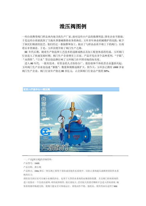
泄压阀图例一些台商携带阀门样品来内地寻找生产厂家,面对这些小产品的微薄利益,国有企业不愿做,于是这些台商就找到了当地从事器械维修业务的渔民。
玉环多年渔业机械维护的实践,赋予了渔民们精湛的技艺。
他们经过一番揣摩和加工,做出了与样品品质不相上下的阀门,台商看后非常满意。
于是,玉环县便开始了阀门生产之路。
80年代后期,随着生产制造和工艺技术的逐渐成熟以及加工配套体系的形成,玉环阀门行业进入了快速发展时期,阀门生产企业增至上百家,产品开发出多个品种系列,“宇锚”、“永得胜”、“巨水”等自创品牌打响了玉环阀门在中国市场的知名度。
进入90年代,一批有技术、有资金的人才纷纷办厂,股份制和个体私营企业蓬勃兴起,玉环阀门生产企业也迅速“膨胀”,数量和规模逐渐扩大。
到今天,玉环县已拥有1000多家阀门生产企业,阀门行业年产值达90多亿元,占全国阀门行业总产值的30%,首页>>产品中心>>泄压阀一、产品[泄压阀]的详细资料:产品型号:500X产品名称:泄压阀产品特点:500x泄压/持压阀王要用于消防或其他供水系统中,以防止系统超压或维持消防供水系统的压力。
消防泵关闭后还可以减小水锤的冲击。
也用于大型供水系统的水锤消除装置.并且阀门控制系统的进口处装有一个自清洁滤网,利用流体特性,使比重较大、直径较大的悬浮颗粒不会进入控制系统.确保系统循环畅通无阻,使阀门能安全可靠地运行。
系统动作平稳、强度高、使用寿命长适用于600口径以下的管道。
二、泄压阀主要外形连接尺寸:D N 20 25 32 40 50 65 80 1012515202530354045L 150 16182020321624129233356495622698787914978H1 463 463463516516525375966537098058559539910301030H 557 557557616162564275808864113511851325138514451445订货须知:一、①泄压阀产品名称与型号②泄压阀口径③泄压阀是否带附件二、若已经由设计单位选定公司的泄压阀型号,请按泄压阀型号三、当使用的场合非常重要或环境比较复杂时,请您尽量提供设计图纸和详细参数,相关产品:流量控制阀可调式减压阀遥控浮球阀液压水位控制阀排泥阀紧急关闭阀压差旁通平衡阀水泵控制液动排泥阀隔膜式多功能水泵控制阀缓闭式止回阀200X减压阀电磁遥控球阀定水位器遥控浮球阀液压水位控制阀WM3隔膜式多功能水泵控制阀当前位置:上海工洲阀门有限公司首页 >> 产品展示 >>水利控制阀>>泄压阀>>安全泄压阀产品名称:安全泄压阀产品型号:AX742X产品口径:DN15-500产品压力:0.6~10.0Mpa产品材质:铸钢、不锈钢、合金钢等产品简介:制造标准:中国GB、机械部JB、化工标准HG、美标API、ANSI、德标DIN、日本JIS、JPI、英标BS生产。
第四部分:移动供气源

四、工作原理
四、工作原理
先打开车架上一只(组)气瓶的瓶阀,然后打开 应急气瓶的瓶阀,高压空气进入气源分配器,经减压 器一级减压后,通过导气长管送至Y型快插接头,分两 路进入不同使用者的供气阀,供气阀将中压气体按照 使用者的吸气量,进行二级减压,减压后的气体进入 面罩,供使用者呼吸使用,人体呼出的气体经面罩上 的呼气阀排至大气。 当导气长管内的气压降至0.1~0.3MPa时,自动转 换器自动转换到应急气瓶供气,并发出报警提示。
五、操作使用
(一)操作程序
1、将30MPa的空气压缩气瓶放到小车的气瓶托盘上,将气 瓶阀口对准十字减压器的联接手轮。保证手轮与气瓶阀联 接良好,并拧紧螺纹。
2、调节好气瓶托盘的高度,使十字减压器所联接的4个气 瓶平稳地安装在小车上,再将托盘底下的螺母拧紧,使气 瓶固定。 3、检查配件箱内的气管、面罩、供气阀、腰带是否齐全、 完好。
Hale Waihona Puke 北京消防总队 张保国移动供气源
两瓶卧式
两瓶立式
四瓶卧式
四瓶立式
移动供气源
移动供气源也称长管空气呼吸器(即气瓶推车), 是一种将气源置于有毒有害工作环境外空气无污染的 场所,通过气瓶压力和导气长管将洁净空气输送到远 端供气阀,供工作人员呼吸用的防护器具 。 移动供气源是一套完整的自给式正压空气呼吸 器装置。特别适合在隧道、管道或其它有限空间中, 以及其它污染环境中完成长时间、大工作量的复杂 工作时使用。
五、操作使用
(三)使用注意 1、工作环境中存在可能影响供气管路的危险因素,应禁止使用。
2、在异常恶劣的环境中使用时要同时使用辅助保护用品,如: 手套,安全鞋,防护服等。
3、使用移动供气源前使用者必须确认是否满足安全使用的条件。
化工设计中常用的安全泄放装置

对 于易 燃 、 易爆 、 有毒 、 吸入 空 气 或少 量 水 分 对 物 料 品质 有 较 大影 响 的物 料 , 需 要 避 免物 料 与 大气
设 施 经常 单独 或 组合 应用 到 各类 设 备 和管路 系
统 中。
接触 , 这 时储 罐 通 常应 考虑 气封 系 统 ( 通常 用氮
化型 的组合 装 置 。 2 . 3 压 力管 道 在化工 设计 中 , 各 类 工艺介 质管 道 、 蒸 汽 等热介 质管 道 , 由于 升 温或 者 误操 作 等各 种 原 因 可能 产 生 超 压 。 因此 , 在上 述 管 道上 设 置 安全 泄 放装 置 也是
必要 的 。安装 于管道 上 的安全 泄放 装置 主要有 安全
泄放 装置 是设 计工作 中极 为重 要 的一个 环节 。
参考文献 :
[ 1 ] 李森林 . 常压储罐的安全泄放设施设 计[ J ] . 辽宁化工 , 2 0 1 4 ( 0 5 ) . [ 2] 刘晓 . 浅谈石油化工常压及低压储 罐安全 泄放设施设 计[ J 1 . 中国
石油和化工标准与质量, 2 0 1 4 , ( 7 ) .
介 质 的特性 , 在设 置安 全泄 放装 置 时也需 特别 考虑 :
阀, 在某 些 高空排放 的管道上 还必 须设 置 阻火器 等 。
其 通 常包 括 内罐 安 全 阀 ( 2 个及 以上 ) 、 外 罐 安全 阀 、
3 结 语
总之 , 安全泄放装置是各类储罐和压力容器 、 压 力管道等设备设施上必不可少 的重要安全附件。根 据 各类 设 备 、 管 道 及操 作介 质 的特点 正 确 选用 安 全
2 . 2 其他 压 力容器
[ 3] 沈佳逸 . 石油化工常压及低压储罐安全泄放设施 设计[ J 1 . 化工设
安全阀标准汇总

安全阀标准汇总标准编号标准中文名称标准英文名称SY/T0525.1-93石油储罐液压安全阀SY/T10006-2000海上井口地面安全阀和水下安全阀规范SY/T10024-1998井下安全阀系统的设计、安装、修理和操作的推荐作法GB/T14087-1993船用空气瓶安全阀Safety valves for marine air vesselJB/T6441-1992(2005复审)压缩机用安全阀JB/T2203-1999弹簧式安全阀结构长度JB/T9624-1999电站安全阀技术条件JB/T53170-1999弹簧直接载荷式安全阀产品质量分等NF E86-512-1-2002冷凝容器.防超压安全设施.第1部分:冷凝设备的安全阀(Cryogenic vessels - Safety devices for protection against excessive pressure - Part 1 : safety valves for cryogenic service.)NF A84-330-1982气焊设备.乙炔发生器用“防回气—断火”的液压安全阀和组合装置.规范和试验(GAS WELDING EQUIPMENT. HYDRAULIC SAFETY SEALS AND COMBINED “NON-RETURN VALVE/FLAME ARRESTOR“ DEVICES FOR ACETYLENE GENERATORS. REQUIREMENTS AND TESTS.)NF E32-110-10-2002水管锅炉和辅助设备.第10部分:防过压安全阀的要求(Water-tube boilers and auxiliary installations - Part 10 : requirements for safeguards against excessive pressure.)NF D36-404-2000建筑阀门.温度和压力组合安全阀.试验和要求(Building valves - Combined temperature and pressure relief valves - Tests and requirements.)NF M87-213-2001石油和天然气工业.下降孔设备.地下安全阀设备(Petroleum and natural gas industries - Downhole equipment - Subsurface safety valve equipment.)NF T81-103-1980液态体化学产品的运输和装卸.底部注入或排放的罐车.内部关闭阀和安全阀.使用压力等于或小于4巴(TRANSPORTATION AND HANDLING OF LIQUID CHEMICAL PRODUCTS. TANKER VEHICLES FILLED AND EMPTIED FROM BELOW. INTERNAL SAFETY AND STOP VALVE. OPERATING PRESSURE EQUAL TO OR LESS THAN 4 BAR.)NF E29-420-1985工业阀门.安全阀.技术说明书样式和协调证明书(INDUSTRIAL VALVES. SAFETY AND RELIEF VALVES. MODEL OF TECHNICAL SPECIFICATIONS AND CONFORMITY CERTIFICATE.)NF P52-001-1975取暖设备用安全阀.一般技术规范(SAFETY VALVES FOR HEATING INSTALLATIONS.)NF E29-413-1989工业阀门.安全阀流量计算.其他方法(INDUSTRIAL VALVE. SAFETY VALVES AND BURSTING DISC(S) DEVICES. CALCULATION OF THEORETICAL FLOWRATE.)NF E29-414-1992工业阀门.安全阀门.安全阀门类型S,G1,L1和L2流率计算示例(INDUSTRIAL VALVES. SAFETY VALVES. EXAMPLES FOR FLOWRATE CALCULATION OF SAFETY VALVES TYPES S,G1,L1 AND L2.)NF E29-415-1990工业阀门.安全阀.G平方型安全阀排出空气当量流量计算实例.GPL标准蓄水池的应用(INDUSTRIAL VALVES. SAFETY VALVES. CALCULATION OF AIR EQUIVALENT FLOW CAPACITY FOR SAFETY VALVES OF TYPE G2. APPLICATION FOR STANDARD VESSELS FOR GPL.)NF E29-421-1987工业阀门.安全阀.安全膜.为获得工作特性的安装规范(Industrial valves. Safety valves. Bursting discs.)NF D36-403-2000建筑阀门.压力安全阀.试验和要求(Building valves - Pressure safety valves - Tests and requirements.)ANSI/UL 132-2002无水氨气和液化石油气的安全阀的安全标准(Standard for Safety for Safety Relief Valves for Anhydrous Ammonia and LP-Gas ) ANSI Z21.22a Addenda-1990热水供给系统用安全阀和煤气自动关闭系统.补充件(Relief valves and automatic gas shutoff devices for hot water supply systems; Addenda) ANSI Z21.22-1986热水供给系统用安全阀和煤气自动关闭系统(Relief valves and automatic gas shutoff devices for hot water supply systems)ANSI/API 527-1991安全阀的阀座紧密性(Seat Tightness of Safety Relief Valves)BS EN 13953-2003液化石油气(LPG)用移动式可填充储气瓶的减压安全阀(Pressure relief valves for transportable refillable cylinders for Liquefied Petroleum Gas (LPG))BS EN 13648-1-2002冷凝容器.防超压保护设施.冷凝设备的安全阀(Cryogenic vessels - Safety devices for protection against excessive pressure - Safety valves for cryogenic service)BS EN 1489-2000建筑物阀门.压力安全阀门.试验和要求(Building valves - Pressure safety valves - Tests and requirements)BS EN ISO 10432-2000石油和天燃气工业.下井设备.地下安全阀设备(Petroleum and natural gas industries - Downhole equipment - Subsurface safety valve equipment)EN ISO 10432-1999石油和天然气工业下降孔设备地下安全阀设备Petroleum and natural gas industries - Downhole equipment - Subsurface safety valve equipment (ISO 10432:1999)EN 1489-2000建筑阀门压力安全阀门试验和要求Building valves - Pressure safety valves - Tests and requirementsprEN 45512-1994采购指南管道系统和阀包括安全阀的锅炉和高压管道阀Guide for procurement - Pipework and valves - Boiler and high pressure piping valves including safety valvesEN 13648-1-2002低温容器抗过压保护安全设备第1部分:低温服务用安全阀Cryogenic vessels - Safety devices for protection against excessive pressure - Part 1: Safety valves for cryogenic serviceprEN ISO 4126-1-2003防止过压防护的安全装置第1部分:安全阀Safety devices for protection against excessive pressure - Part 1: Safety valves(ISO/FDIS 4126-1:2003)prEN ISO 4126-4-2003保护额外压力的安全设备第4部分:飞行员操作安全阀Safety devices for the protection against excessive pressure - Part 4: Pilot operated safety valves (ISO/FDIS 4126-4:2003)BS 1123-1-1987压缩空气或惰性气体装置用安全阀、计量表和易熔塞.第1部分:安装实用规程(Safety valves, gauges and fusible plugs for compressed air or inert gas installations - Code of practice for installation)BS 6759-2-1984安全阀.第2部分:惰性气体或压缩空气用安全阀规范(Safety valves - Specification for safety valves for compressed air or inert gases)BS 6759-1-1984安全阀.第1部分:蒸汽与热水用安全阀规范(Safety valves - Specification for safety valves for steam and hot water)BS 6759-3-1984安全阀.第3部分:工作流体用安全阀规范(Safety valves - Specification for safety valves for process fluids)DIN 3394-3-2004自动控制阀.第3部分:压力为4巴及以下的0级减压安全阀(Automatic control valves - Part 3: Class 0 pressure relief, valves for pressure up to 4 bar) DIN 5589-1990有轨车辆的压缩空气装置.安全阀.安装和连接尺寸.要求(Compressed air equipment for rail vehicles; safety valves; mounting and connecting dimensions, requirements)DIN EN ISO 10432-2000石油和天燃气工业.下山巷道设备.地下安全阀规范(Petroleum and natural gas industries - Downhole equipment - Subsurface safety valve equipment (ISO 10432:1999); German version EN ISO 10432:1999)DIN 87901-2001泵用双向安全阀(Sniffle valves for pumps)DIN EN 1489-2000建筑物阀门.压力安全阀门.试验和要求(Building valves - Pressure safety valves - Tests and requirements; German version EN 1489:2000)DIN EN 13648-1-2002冷凝容器.防超压保护设施.第1部分:冷凝设备的安全阀(Cryogenic vessels - Safety devices for protection against excessive pressure - Part 1: Safety valves for cryogenic service; German version EN 13648-1:2002)DL/T959-2005电站锅炉安全阀应用导则JIS B8652-2002比例电动液压减压阀及安全阀的试验方法(Test methods for electro-hydraulic proportional pressure relief valves andelectro-hydraulic proportional pressure reducing and relieving valves)JIS B8210-1994蒸汽锅炉和压力容器.弹簧式安全阀(Steam boilers and pressure vessels -- Spring loaded safety valves)JIS B8414 AMD 1-2003热水器用安全阀(修改件1)(Relief valves for hot water appliances (Amendment 1))JIS B8210 ERRATUM 1-2001蒸汽锅炉和压力容器.弹簧式载荷安全阀(勘误1)(Steam boilers and pressure vessels -- Spring loaded safety valves (Erratum 1))JIS B8225-1993安全阀排放系数的测定方法(SAFETY VALVES - MEASURING METHODS FOR COEFFICIENT OF DISCHARGE) JIS E7701-1992高压气罐车用气罐安全阀(Safety valves for high pressure gas tank car tanks)JIS B8414-1999热水器用安全阀(Relief valves for hot water appliances)ISO 4126-1-1991安全阀.第1部分:通用要求(Safety valves; part 1: general requirements)ISO 10417-1993石油和天然气工业.地下安全阀系统.设计、装配、操作和修理(Petroleum and natural gas industries; subsurface safety valve systems; design, installation, operation and repair)GB/T12241-2005安全阀一般要求GB/T12243-2005弹簧直接载荷式安全阀HG 3157-2006液化气体罐车用弹簧安全阀1.分类目前大量生产的安全阀有弹簧式和杆式两大类。
- 1、下载文档前请自行甄别文档内容的完整性,平台不提供额外的编辑、内容补充、找答案等附加服务。
- 2、"仅部分预览"的文档,不可在线预览部分如存在完整性等问题,可反馈申请退款(可完整预览的文档不适用该条件!)。
- 3、如文档侵犯您的权益,请联系客服反馈,我们会尽快为您处理(人工客服工作时间:9:00-18:30)。
BRITISH STANDARDBS 341-4:2004Transportable gas container valves —Part 4: Pressure relief devices12 &23<,1* :,7+287 %6, 3(50,66,21 (;&(37 $6 3(50,77(' %< &23<5,*+7 /$:移动式气瓶阀门 第4部分:压力泄放装置.b zf xw .c omBS 341-4:2004This British Standard, having been prepared under the direction of the StandardsPolicy and Strategy Committee, was published on 15January 2004© BSI 15 January 2004The following BSI references relate to the work on this British StandardCommittee reference PVE/3/1Draft for comment 00/716619 DC ISBN 0 580 43113 4Committees responsible for this British StandardThe preparation of this British Standard was entrusted by TechnicalCommittee, PVE/3, Gas containers, to Subcommittee PVE/3/1, Valve fittings for gas cylinders, upon which the following bodies were represented:L P Gas Association Ministry of DefencePersonal Safety Manufacturer’s Association Scuba Industries Trade Association Ltd.Amendments issued since publicationTextAmd No.Commentsw ww .ba ba ke .n e tBS 341-4:2004© BSI 15 January 2004iContentsCommittees responsible Inside front coverForeword ii1Scope12Normative references 13Terms anddefinitions14Design of pressure relief devices 25Relief pressure 36Bursting disc test37Installation and application of pressure relief devices3w ww .ba ba ke .n e tBS 341-4:2004ii© BSI 15 January 2004ForewordThis part of BS 341 has been prepared by Subcommittee PVE/3/1 on behalf of Technical Committee PVE/3 and partially supersedes BS 341-1:1991, which is obsolescent.BS 341-1:1991 detailed all aspects of the design, manufacture and testing of valves fitted to containers used for the conveyance of permanent, liquefiable and dissolved gases, except those for liquefied petroleum gas (LPG) applications. a future CEN BS 341,Transportable gas container valves , is published in four parts:— Part 1: Specification for industrial valves for working pressures up to and including 300 bar (obsolescent);— Part 2: Valves with taper stems for use with breathing apparatus (obsolescent);— Part 3: Valve outlet connections;— Part 4: Pressure relief devices.This publication does not purport to include all the necessary provisions of a contract. Users are responsible for its correct application.Compliance with a British Standard does not of itself confer immunity from legal obligations .Summary of pagesThis document comprises of a front cover, an inside front cover, pages i and ii, pages 1 to 3 and a back cover.The BSI copyright notice displayed in this document indicates when the document was last issued.w ww .ba ba ke .n e tBS 341-4:2004© BSI 15 January 200411 ScopeThis part of BS 341 specifies requirements for the design and application of pressure relief devices for use with transportable gas cylinders manufactured for conveyance and storage of compressed, liquefied and dissolved gases for industrial and medical applications.This part of BS 341 does not include requirements for pressure relief devices for liquefied petroleum gas (LPG).This part of BS 341 applies to pressure relief devices for containers limited to a charging pressure of 300bar)1) gauge. (Developed pressures for particular gases may exceed this pressure.)2 Normative referencesThe following referenced documents are indispensable for the application of this document. For dated references, only the edition cited applies. For undated references, the latest edition of the referenced document (including any amendments) applies.BS 2915:1990, Specification for bursting discs and bursting disc devices.BS EN 1802, Transportable gas cylinders — Periodic inspection and testing of seamless aluminium gas cylinders.BS EN 1803, Transportable gas cylinders — Periodic inspection and testing of welded carbon steel gas cylinders.BS EN 1968, Transportable gas cylinders — Periodic inspection and testing of seamless steel gas cylinders.BS EN 12863, Transportable gas cylinders — Periodic inspection and maintenance of dissolved acetylene cylinders.BS EN ISO 11114-1, Transportable gas cylinders — Compatibility of cylinder and valve materials with gas contents — Part 1: Metallic materials.BS EN ISO 11114-2, Transportable gas cylinders — Compatibility of cylinder and valve materials with gas contents — Part 2: Non-metallic materials.BS EN ISO 14246, Transportable gas cylinders — Gas cylinder valves — Manufacturing tests and inspections.3 Terms and definitionsFor the purposes of this part of BS 341, the following terms and definitions apply.3.1pressure relief devicedevice designed to reduce the possibility of failure of a charged container from excessive pressure particularly when the container is exposed to heat3.2pressure relief valvepressure relief device that is in direct contact with the gas, and is designed to open and close within predetermined pressure limits3.3bursting discpressure relief device consisting of a disc that is in direct contact with the gas and is designed to rupture 3.4fusible pluglimits of temperature and permit the discharge of the contained gas1)1 bar = 105 N/m2 = 100 kPa.w ww .ba ba ke .n e tBS 341-4:20042© BSI 15 January 20043.5flow rating pressurepressure at the inlet of a pressure relief device which is used for establishing its rated flow capacity 3.6rated flow capacityrating pressure3.7specified bursting pressurenominal pressure at which a bursting disc is designed to rupture3.8maximum bursting pressurespecified bursting pressure plus the upper permitted design tolerance 3.9leakageunintended flow of gas or liquid in excess of 5mbar ·l/h 2)4 Design of pressure relief devices4.1 There shall be no significant change in the function of the device and no detrimental corrosion ordeterioration of the materials due to normal service conditions of the container to which it is fitted within the following period.— For valves fitted to seamless steel containers (excluding dissolved acetylene containers) of water capacity 0.5 l and above, the inspection periods shall be as specified in BS EN 1968.— For valves fitted to welded steel containers (excluding dissolved acetylene containers) of water capacity 0.5 l up to 150 l, the inspection periods shall be as specified in BS EN 1803.— For valves fitted to seamless aluminium alloy containers (excluding dissolved acetylene containers) of water capacity 0.5 l and above, the inspection periods shall be as specified in BS EN 1802.— For valves fitted to dissolved acetylene containers, the inspection periods shall be as specified in BS EN 12863.4.2 The breakage or failure of any internal component shall not obstruct free and full discharge of the gas through the pressure relief device.4.3 The materials of construction shall be mutually compatible and compatible with the gas(es) to be conveyed (see BS EN ISO 11114-1 and BS EN ISO 11114-2) and other service conditions, e.g. to prevent room temperature bonding of relief valve seat pads to relief valve seats. 4.4 The design shall be such as to deter tampering.4.5 The outlets from all pressure relief devices shall be so designed and constructed as to minimize the collection of moisture or other foreign matter that could adversely affect the performance of the device. The outlets from all pressure relief devices shall be so sited that free discharge from the devices is not impaired, and the jet thrust effect of such discharges does not impose destabilizing forces on the container.4.6 All pressure relief devices shall be designed and fitted so as to ensure that the cooling effect of the discharge does not prevent the effective operation of the devices.4.7 Pressure relief devices shall be sized to be capable, under the most severe design requirements(e.g.exposure to fire), of a discharge rate that prevents the pressure of the container contents exceeding the test pressure of the container.The minimum rated flow capacity for pressure relief devices fitted to non-insulated containers having water capacities of 11 l or more shall be as follows.2)5 mbar·l/h . 10–3 torr·l/s = 133.3 × 10⁻⁶ N·m/s. An approximate indication of this leakage rate would be the formation of four 3.5 mm diameter or ten 2.5 mm diameter bubbles per minute.w ww .ba ba ke .n e tBS 341-4:2004© BSI 15 January 20043a) For compressed gases:Q 1 = 0.00967W c whereQ 1 is the rated flow capacity in cubic metres per minute of free air at 7 bar absolute;W c is the water capacity of the container in litres.b) For liquefied gases: the rated flow capacity of the pressure device shall be twice that given by the equation in item a).For containers having water capacities of less than 11 l, the rated flow capacity shall be as given in items a) and b), except that the value of W c shall be 11, i.e. the rated flow capacity shall be 0.10637 m 3/min.4.8 The yield temperature for fusible plugs used with acetylene containers shall be (100±2)°C.4.9 The methods of manufacture, inspection and test shall conform to those of the valve, as specified in BS EN ISO 14246.4.10 Bursting discs shall conform to BS 2915:1990, except that flat discs may be used, and shall be designed so as to ensure that rupture occurs at a pressure not greater than the test pressure of the container. If a container is liable to be subject to vacuum conditions during service, the bursting disc shall be fitted with vacuum supports.NOTE Where flat discs are used, special measures should be taken in valve production to ensure it is not possible for more than one disc to be fitted to a valve.4.11 Where practicable, fusible plugs shall be externally marked to indicate the temperature at which they are designed to operate.5 Relief pressureWhere the pressure relief device is a bursting disc fitted to the valve of a seamless or welded container, the maximum bursting pressure shall not exceed the test pressure of the container.Container valves are designed to operate between –20°C and +60°C and relief devices shall therefore be specified to operate within this temperature range.For containers used in carbon dioxide service, the minimum burst pressure shall be no less than 180bar g.6 Bursting disc testA number of bursting discs shall be subjected to a burst test in accordance with BS 2915:1990 to check that disc rupture occurs within its prescribed range (see Clause 5).The number of bursting discs to undergo this test shall be subject to agreement between purchaser and manufacturer.NOTEThese burst tests should be carried out with the disc in the valve body.7 Installation and application of pressure relief devicesValves to be fitted to containers filled with a toxic gas shall not be fitted with a pressure relief device.The design and location of a pressure relief device shall be compatible with the intended duty.Containers of 3.5 l water capacity and above which are filled with CO 2 for industrial purposes shall be fitted with pressure relief devices.gases.°C or other such pressure relief devices as approved by the Health and Safety Executive.NOTE The Health and Safety Executive should be consulted if it is proposed to fit containers, other than dissolved acetylene containers, with fusible plugs.w ww .ba ba ke .n e tBS 341-4:2004BSI389 Chiswick High Road London W4 4ALBSI —British Standards InstitutionBSI is the independent national body responsible for preparingBritish Standards. It presents the UK view on standards in Europe and at the international level. It is incorporated by Royal Charter.RevisionsBritish Standards are updated by amendment or revision. Users ofBritish Standards should make sure that they possess the latest amendments or editions.Tel:+44+44(0)2089967400.BSI offers members an individual updating service called PLUS which ensures that subscribers automatically receive the latest editions of standards.Buying standardsOrders for all BSI, international and foreign standards publications should be addressed to Customer Services. Tel:+44(0)2089969001.Fax:+44(0)2089967001. Email:orders@. Standards are also available from the BSI website at .In response to orders for international standards, it is BSI policy to supply the BSI implementation of those that have been published as British Standards, unless otherwise requested.Information on standardsBSI provides a wide range of information on national, European andinternational standards through its Library and its Technical Help to Exporters Service. Various BSI electronic information services are also available which give details on all its products and services. Contact the Information Centre.Tel:+44(0)2089967111. Fax:+44(0)2089967048. Email:info@.Subscribing members of BSI are kept up to date with standards developments and receive substantial discounts on the purchase price of standards. For details of these and other benefits contact Membership Administration. Tel:+44(0)2089967002. Fax:+44(0)2089967001. Email:membership@.Information regarding online access to British Standards via British Standards Online can be found at /bsonline.Further information about BSI is available on the BSI website at .CopyrightCopyright subsists in all BSI publications. BSI also holds the copyright, in the UK, of the publications of the international standardization bodies. Except as permitted under the Copyright, Designs and Patents Act 1988 no extract may be reproduced, stored in a retrieval system or transmitted in any form or by any means – electronic, photocopying, recording or otherwise – without prior written permission from BSI.This does not preclude the free use, in the course of implementing the standard, of necessary details such as symbols, and size, type or grade designations. If these details are to be used for any other purpose than implementation then the prior written permission of BSI must be obtained.Details and advice can be obtained from the Copyright & Licensing Manager. Tel:+44(0)2089967070. Fax:+44(0)2089967553. Email:copyright@.w ww .ba ba ke .n e t。